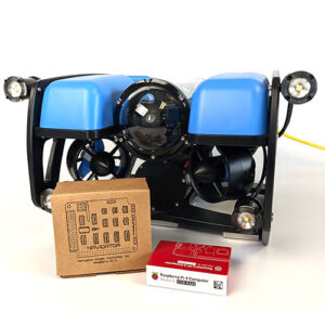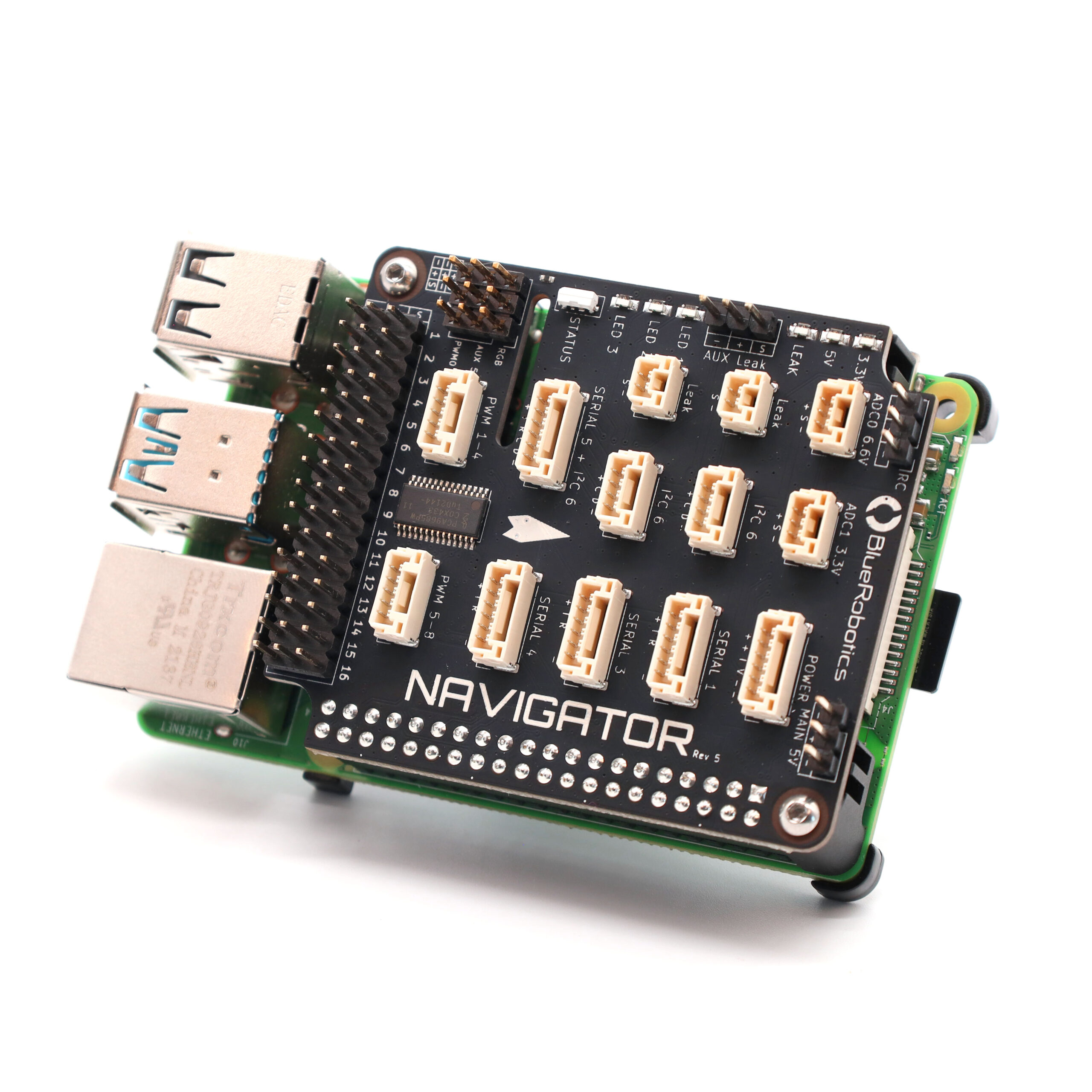
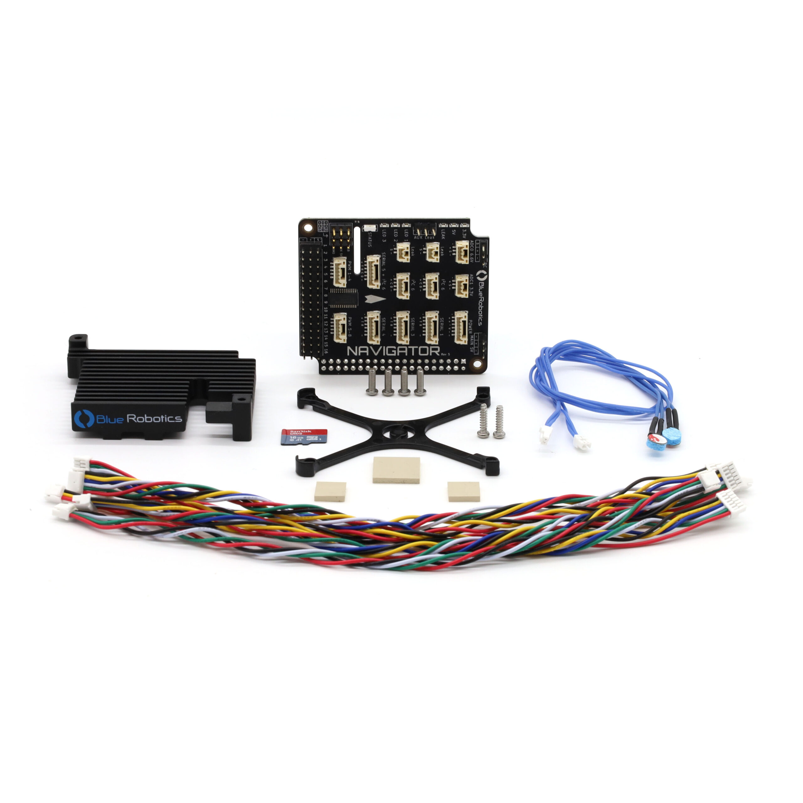
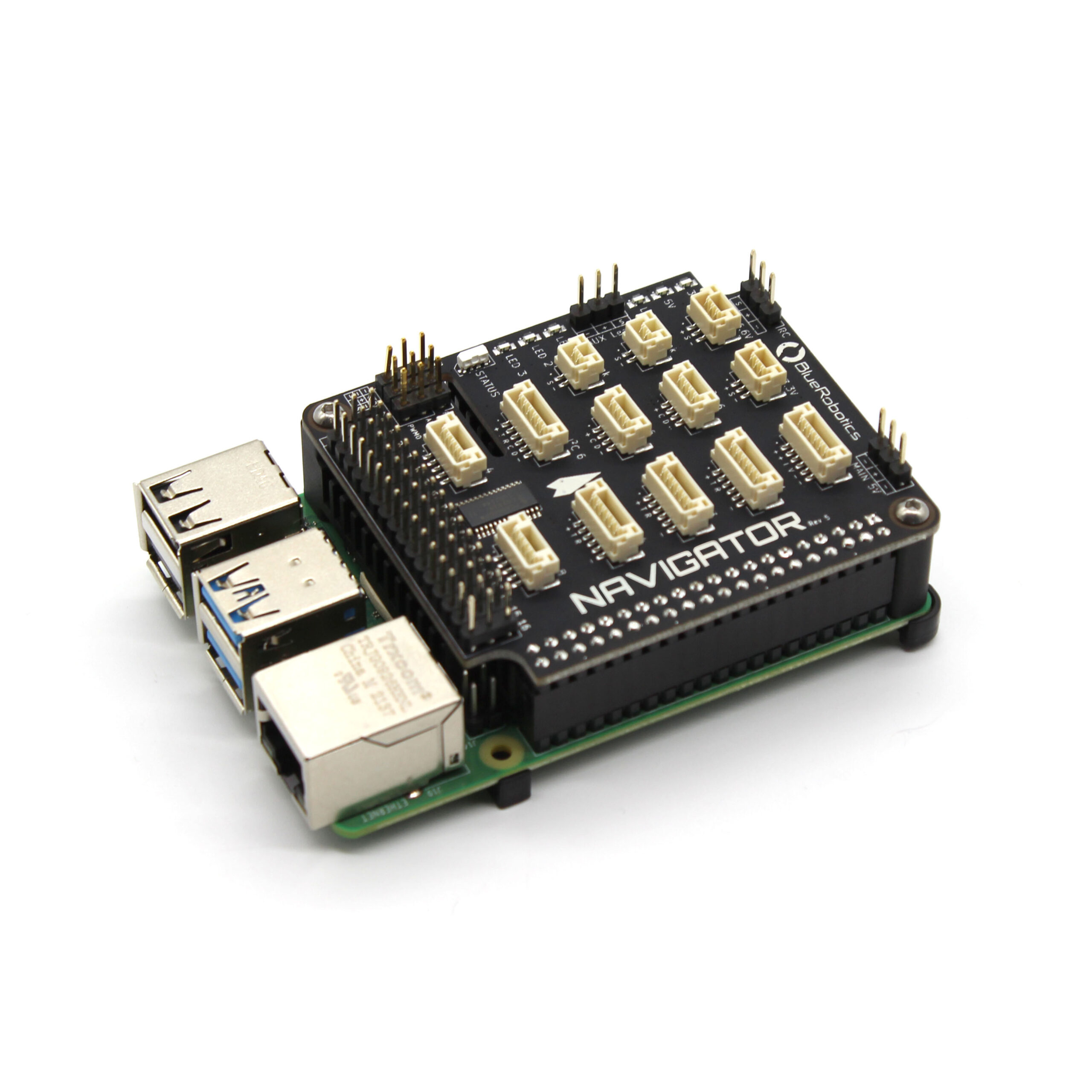
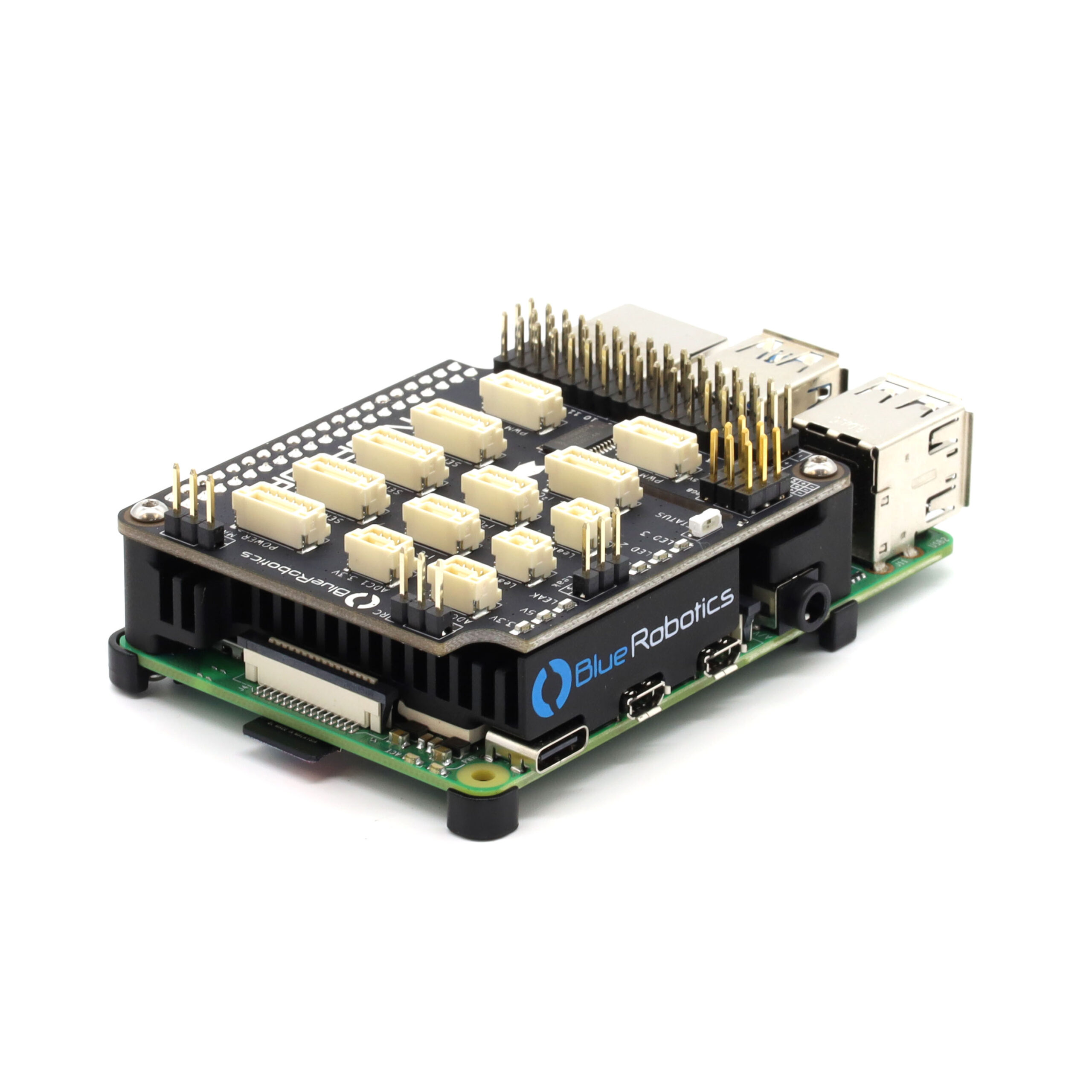
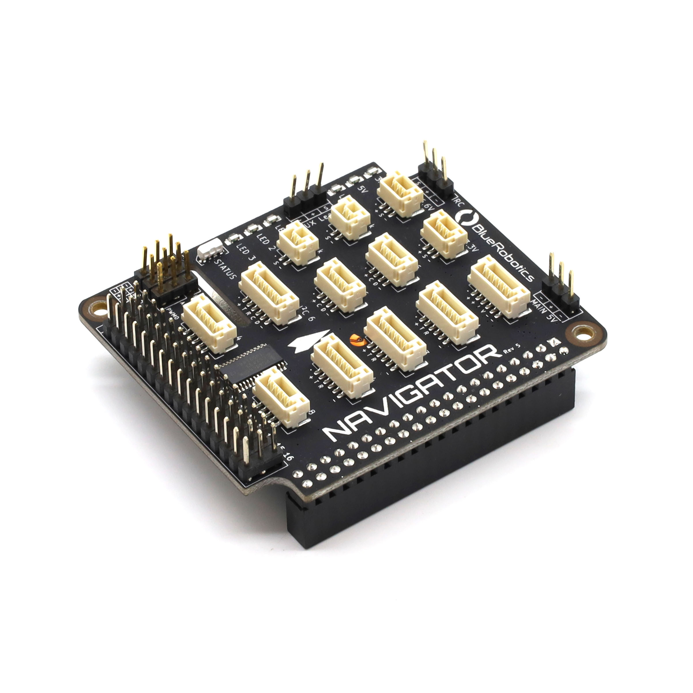
The Navigator is an expansion board that plugs into the Raspberry Pi 4 and turns it into a fully-featured flight controller, ready to power ROVs, USVs, drones, ground vehicles, and just about anything that moves!
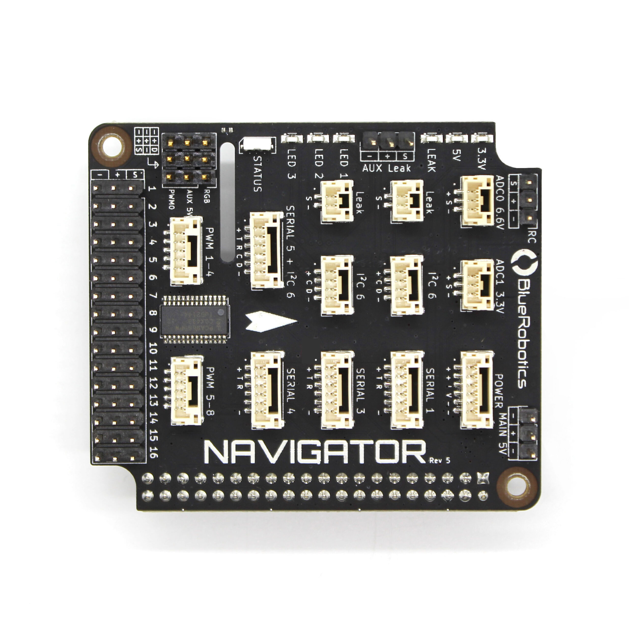
At its core, the Navigator is a collection of inputs and outputs. It has inputs from onboard sensors, outputs to servos or speed controllers, and expansions ports that can be connected to external devices.
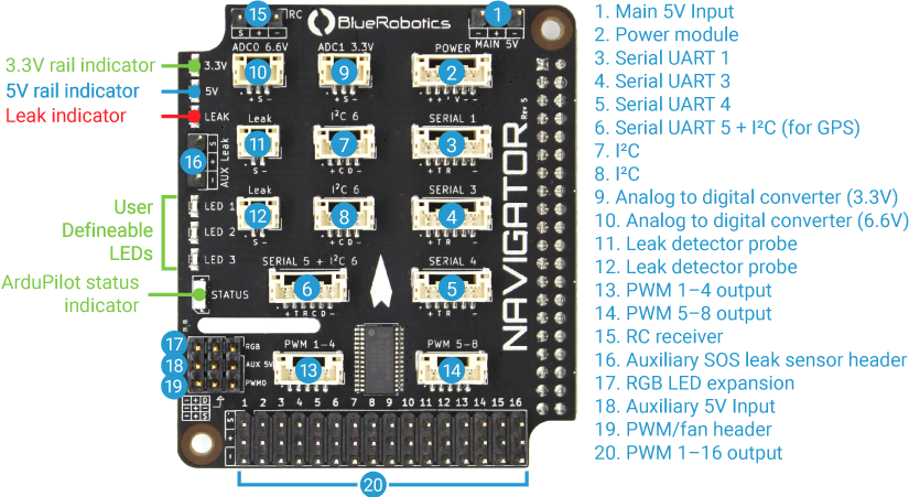
Onboard, the Navigator has:
- 6-axis IMU with accelerometers and gyroscopes for orientation
- Dual three-axis magnetometers for compass heading
- Barometer for altitude in air
- 16 servo PWM channel outputs
- Current and voltage ADC inputs
- Built-in leak detection for 2 probes
- RC receiver input (SBUS)
- RGB status LED