
Navigator Hardware Setup
Guides in This Series
Navigator Hardware Setup
Navigator Software Setup

Navigator Developer Guide
Introduction
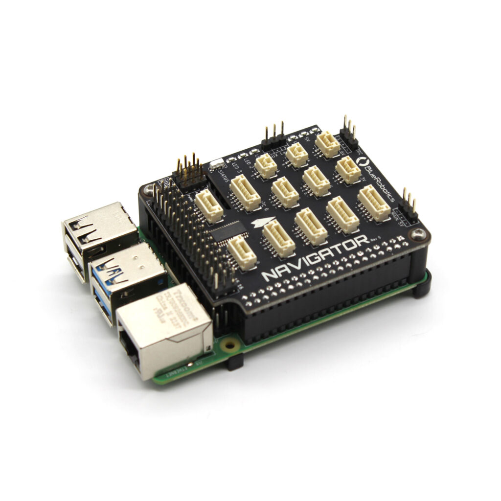
The Navigator is an add on board for the Raspberry Pi 4 that enables autonomous vehicles running ArduPilot and BlueOS. The board is equipped with a suite of sensors to enable autonomous vehicle control with the Raspberry Pi 4 including digital accelerometer, gyroscope, dual magnetometers, ADC and pressure sensor. It also includes a rich set of connectors for connecting all of your vehicle’s hardware like servos, motor controllers, sonar, GPS and other sensor peripherals.
The Navigator is used on the BlueROV2 and BlueBoat in conjunction with BlueOS software, but it can also be used for a wide range of robotics applications such as ROVs, USVs, drones, ground vehicles, and just about anything that moves!
This guide will go over assembling the Navigator kit and the hardware setup. Along with the information in this guide, be sure to visit the ArduPilot documentation for in depth information for the type of vehicle you are building.
In the Box
The Navigator kit comes with the following components in the box:
- 1 x Navigator PCB
- 1 x Navigator heatsink
- 1 x Raspberry Pi mounting standoff
- 1 x 128GB microSD card with BlueOS
- 3 x Thermal pads
- 2 x 3-pin JST GH cable for accessories/expansion
- 1 x 4-pin JST GH cable for accessories/expansion
- 3 x 6-pin JST GH cable for accessories/expansion
- 2 x SOS leak probe, 12″ length
- 4 x M2.5×8 button head cap screw
- 2 x #3-28×3/8 mounting screw
The Raspberry Pi 4 is not included in the kit but can be purchased together.
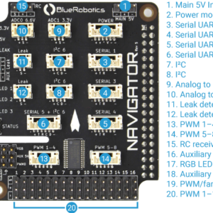
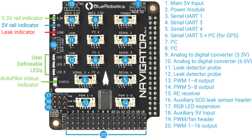
Hardware Overview
Navigator PCB Schematic (PDF)
All sensor and IC datasheets are available in the Navigator technical details.
Compatibility
The Navigator is compatible with the following Raspberry Pi models:
- Raspberry Pi 4 Model B
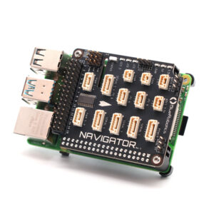
Assembling the Navigator Stack
The Navigator kit includes all the required components and hardware to connect it to a Raspberry Pi. To assemble the Navigator stack, you will need:
- Navigator PCB
- Navigator Heatsink
- Raspberry Pi 4 Model B
- Thermal Pads
- Raspberry Pi Mounting Standoff
- 4 x M2.5×8 Button Head cap screw
You will also need the following tools:
- 1.5 mm hex driver
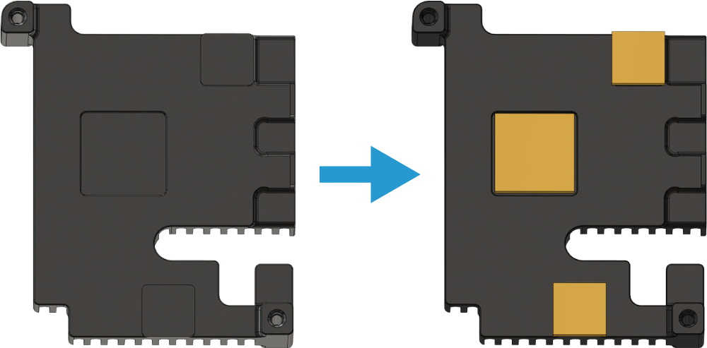
1. Remove the protective covering from the square thermal pads and apply them to the underside of the Navigator heatsink. The heatsink has squares showing where the thermal pads should be placed.
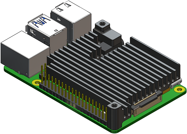
2. Place the Navigator heatsink on top of the Raspberry Pi. The thermal pads should sit between the Navigator heatsink and the Raspberry Pi.
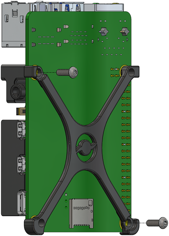
3. Place the Raspberry Pi mounting standoff on the underside of the Raspberry Pi. Use two M2.5×8 button head screws and the 1.5 hex driver to secure the standoff and Navigator heatsink to the Raspberry Pi. The screws should sit in the recessed standoff mounting holes and screw into the heatsink.
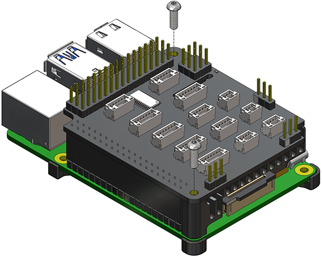
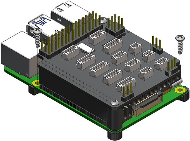
4. Place the Navigator PCB on top of the Raspberry Pi and heatsink and plug it fully onto the Raspberry Pi GPIO pins. Secure the Navigator PCB to the heatsink using the remaining M2.5×8 button head screws.
The Navigator Stack is now ready to mount in your vehicle.
Mounting
The Navigator can be mounted in your vehicle using the included #3-28×3/8 thread forming screws.
The default mounting orientation for the Navigator is with the Navigator PCB facing topside up and the arrow pointing towards the front of the vehicle.
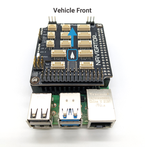
The Navigator stack can also be mounted on the vehicle in a number of different orientations supported by the autopilot software. If you are not using the default orientation, you can specify your mounting orientation during the sensor calibration step in the software setup guide.
Supplying Power
The Navigator has two independent power circuits, the main circuit is powered by the primary and secondary power inputs, and the other is powered by the AUX 5V power input. The diagram below shows which ports are connected to each circuit.
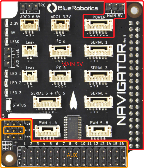
The Navigator has two power inputs that supply power to the Navigator PCB and Raspberry Pi. The voltage supplied to either of these inputs must be 5–5.35V. The power supply used should be capable of delivering at least 4.5 amps. The Navigator + Raspberry Pi will be powered when using either power input.
Main 5V (Primary)
The Main 5V input is the primary power input. This input accepts regular servo-style 3 position 0.1″ pitch female headers. The Blue Robotics 5V6A Power Supply is recommended but any 5V UBEC that can supply at least 4.5A will work.
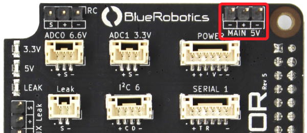
| MAIN 5V | ||
|---|---|---|
| Connector Pinout | 1 - GND 2 - Vin 3 - GND | GND 5 V Supply GND |
| Connector Type | 3 position 0.1″ pitch male header pins | |
| Mating Connector | 3 position 0.1″ pitch female header | |
POWER (Secondary)
Navigator can also be powered using a power module connected to the POWER port. This port is also used to connect analog power modules to measure and provide voltage and current consumption information.
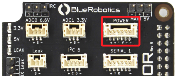
| POWER | ||
|---|---|---|
| Connector Pinout | 1 - Vin 2 - Vin 3 - Current sense 4 - Voltage sense 5 - GND 6 - GND | 5 V Supply 5 V Supply 3.3 V 3.3 V GND GND |
| JST GH Connector Type | BM06B-GHS-TBT(LF)(SN)(N) | |
| Mating JST GH Plug and Crimp Pins | GHR-06V-S (housing) SSHL-002T-P0.2 (pin) |
|
Power Switching
The primary MAIN 5V and secondary POWER inputs may be powered simultaneously. In this case, the Navigator Stack will draw power from the primary MAIN 5V input unless the voltage at the primary input dips below 4.7V. In this event, the Navigator will switch to draw power from the secondary POWER input until the primary input voltage is above 5.1V, then the Navigator will switch back to the primary power input. It is advised to use a power supply capable of delivering at least 4.5 amps to avoid input switching events.
Auxiliary Power Input
The AUX 5V input supplies power to the servo rail, the RGB header, and PWM0 header. To power any servos or other devices connected to these outputs a power supply must be connected to the AUX 5V input. The input voltage connected to the AUX 5V input is delivered to all devices connected to the servo rail, RGB header, and PWM0 header. Ensure that the input voltage range specification of any devices connected to the servo rail, RGB header, or PWM0 header is compatible with the voltage supplied.
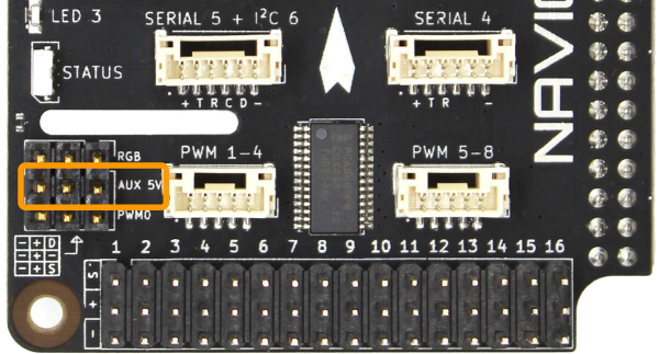
| AUX 5V | ||
|---|---|---|
| Connector Pinout | 1 - GND 2 - Vin 3 - GND | GND 5 V Auxiliary supply GND |
| Connector Type | 3 position 0.1″ pitch male header pins | |
| Mating Connector | 3 position 0.1″ pitch female header | |
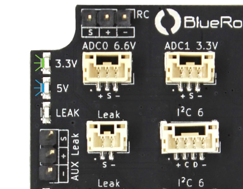
Power Indicator LEDs
There are two power status indicator LEDs on the Navigator.
5V LED: Indicates the Navigator board is receiving power.
3.3V LED: Indicates the Navigator board is providing power to the on-board electronics.
Servos and ESCs
Powering the Servo Rail
The primary MAIN 5V and secondary POWER inputs do not supply power to the servo rail so it must be powered separately using the AUX 5V input. Power can also be supplied using a BEC connected to any of the PWM output channels. The input voltage connected to the AUX 5V input or servo rail is delivered to all devices connected to the servo rail, RGB header, and PWM0 header. Ensure that the input voltage range specification of any devices connected to the servo rail, RGB header, or PWM0 header is compatible with the voltage supplied.
Servo Rail/PWM Output
ESCs and servos can be connected to PWM outputs 1–16. The output can also be configured as 3.3V digital outputs to control relays, switches, etc. The maximum current available on each signal pin to drive relays, etc., is 15 mA
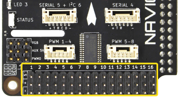
| PWM 1–16 | ||
|---|---|---|
| Connector Pinout | 1 - PWM Signal 2 - V (Aux) 3 - GND | 3.3 V V (Aux) GND |
| Max Signal Current Draw | 15 mA | |
| Connector Type | 3 position 0.1″ pitch male header pins | |
| Mating Connector | 3 position 0.1″ pitch female header | |
JST GH PWM Connectors
PWM output channels 1–8 are also available on JST GH connectors located above the servo rail. These PWM signals are connected to both the JST GH connector and the servo rail, so the same signal will be present on both connectors. The JST GH connectors are intended for higher density wiring in space constrained applications like wiring 4-in-1 ESCs.
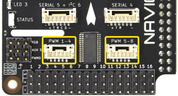
| PWM 1–4 | ||
|---|---|---|
| Connector Pinout | 1 - PWM01 2 - PWM02 3 - PWM03 4 - PWM04 5 - GND | 3.3 V 3.3 V 3.3 V 3.3 V GND |
| Max Signal Current Draw | 15 mA | |
| JST GH Connector Type | BM05B-GHS-TBT(LF)(SN)(N) | |
| Mating JST GH Plug and Crimp Pins | GHR-05V-S (housing) SSHL-002T-P0.2 (pin) |
|
| PWM 5–8 | ||
|---|---|---|
| Connector Pinout | 1 - PWM05 2 - PWM06 3 - PWM07 4 - PWM08 5 - GND | 3.3 V 3.3 V 3.3 V 3.3 V GND |
| Max Signal Current Draw | 15 mA | |
| JST GH Connector Type | BM05B-GHS-TBT(LF)(SN)(N) | |
| Mating JST GH Plug and Crimp Pins | GHR-05V-S (housing) SSHL-002T-P0.2 (pin) |
|
RC Radio
An RC radio can be connected to the RC input connector. Both inverted and noninverted RC protocols are supported.
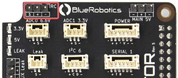
| RC | ||
|---|---|---|
| Connector Pinout | 1 - Serial 2 - VCC 3 - GND | 3.3 V 5 V GND |
| Connector Type | 3 position 0.1″ pitch male header pins | |
| Mating Connector | 3 position 0.1″ pitch female header | |
UART/SBUS Jumper
By default the RC input is configured for SBUS (inverted) protocol. To use a radio that uses a normal (noninverted) UART signal, cut the trace between the SBUS and center solder pad and solder the jumper on the back of the Navigator PCB to the UART position. To reconfigure the RC input for SBUS after the trace has been cut, solder the jumper in the SBUS position.
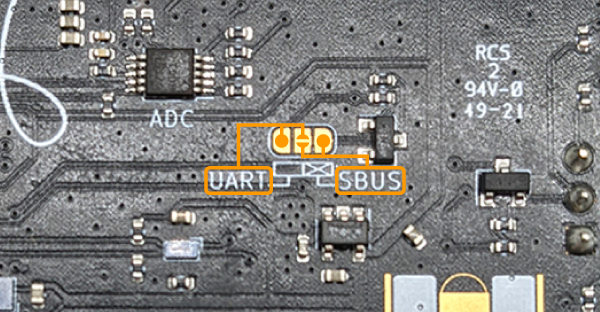
The table below shows common RC serial protocols and the required jumper configuration.
| Manufacturer | Serial Protocol | UART Signal | Jumper Position |
|---|---|---|---|
| FRSky | SBUS | Inverted | SBUS (default) |
| FRSky | IBUS | Noninverted | UART |
| Team BlackSheep | Crossfire | Noninverted | UART |
Serial Devices
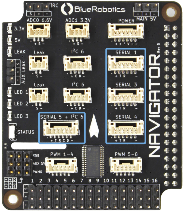
Serial devices may be connected to the 6-pin serial (SERIAL 1,3,4,5) connectors. Additional serial devices may be connected to the Raspberry Pi 4 USB ports via a USB-UART adapter like the BLUART.
| SERIAL 1, SERIAL 3, SERIAL 4 | ||
|---|---|---|
| Blue Robotics Connector Standard Reference | ||
| Connector Pinout | 1 - VCC 2 - TX (out) 3 - RX (in) 4 - Empty 5 - Empty 6 - GND | 5 V 3.3 V 3.3 V GND |
| Interface | UART | |
| Serial 1 Path | /dev/ttyS0 | |
| Serial 3 Path | /dev/ttyAMA1 | |
| Serial 4 Path | /dev/ttyAMA2 | |
| Serial 1 Baud Rate | 1200 Bd–2 MBd | |
| Serial 3, Serial 4 Baud Rate | 1200 Bd–3 MBd | |
| Maximum Power | 1 A | |
| JST GH Connector Type | BM06B-GHS-TBT(LF)(SN)(N) | |
| Mating JST GH Plug and Crimp Pins | GHR-06V-S (housing) SSHL-002T-P0.2 (pin) |
|
Telemetry Radio
Telemetry radios may be connected to any of the 6-pin serial connectors. The recommended setup is to use SERIAL 1 for a telemetry radio connection.
GPS
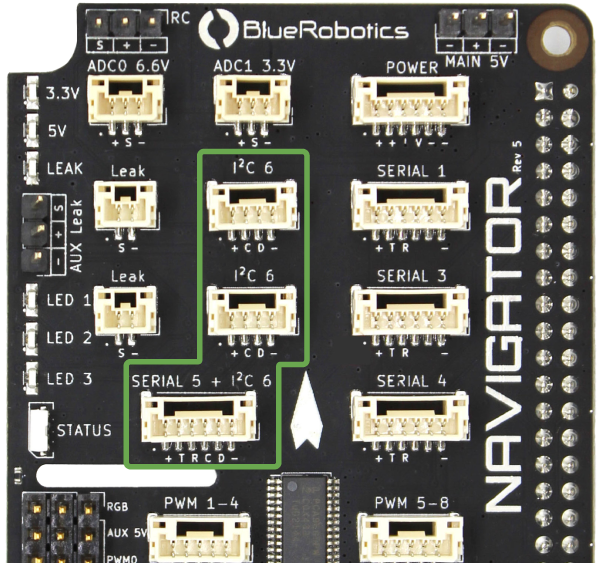
A serial GPS module may be connected to any of the 6-pin serial connectors. Some Dronecode compatible GPS modules also include onboard I2C devices like compasses and barometers. These modules should be connected to the SERIAL 5 + I2C 6 connector in order to use the I2C devices on the GPS module.
Pinout:| SERIAL 5 + I2C 6 | ||
|---|---|---|
| Connector Pinout | 1 - VCC 2 - TX (UART out) 3 - RX (UART in) 4 - SCL (I2C) 5 - SDA (I2C) 6 - GND | 5 V 3.3 V 3.3 V 3.3 V 3.3 V GND |
| Interface | UART + I2C | |
| UART Path | /dev/ttyAMA3 | |
| I2C Path | /dev/i2c-6 | |
| UART Baud Rate | 1200 Bd–3 MBd | |
| I2C Baud Rate | 10 kHz–1 MHz | |
| Maximum Power | 1 A | |
| JST GH Connector Type | BM06B-GHS-TBT(LF)(SN)(N) | |
| Mating JST GH Plug and Crimp Pins | GHR-06V-S (housing) SSHL-002T-P0.2 (pin) |
|
I2C Devices
I2C sensors should be connected to the I2C 6 ports. The I2C bus is also accessible from the SCL and SDA pins on the SERIAL 5 + I2C connector. The clock and data lines on the I2C connectors are connected in parallel, and connect to the Raspberry Pi 4 SOC I2C 6 unit. External pullup resistors are optional, there are pullup resistors on the Navigator PCB.
| I2C 6 | ||
|---|---|---|
| Blue Robotics Connector Standard Reference | ||
| Connector Pinout | 1 - VCC 2 - SCL 3 - SDA 4 - GND | 5 V 3.3 V 3.3 V GND |
| Interface | I2C | |
| Path | /dev/i2c-6 | |
| Baud Rate | 10 kHz–1 MHz | |
| Maximum Power | 1 A | |
| JST GH Connector Type | BM04B-GHS-TBT(LF)(SN)(N) | |
| Mating JST GH Plug and Crimp Pins | GHR-04V-S (housing) SSHL-002T-P0.2 (pin) |
|
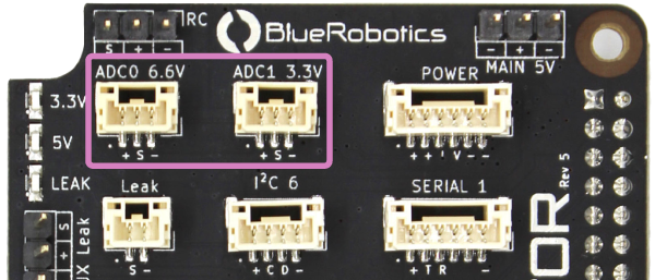
Analog Devices
There are two analog-to-digital converter connectors, one with a 0–3.3V signal input, and one with a 0–6.6V signal input. Ensure that the signal voltage applied to these connectors is within the indicated allowable range. If these limits are exceeded, the ADC may be permanently damaged.
| ADC0 6.6V | ||
|---|---|---|
| Connector Pinout | 1 - VCC 2 - Signal 3 - GND | 5 V 0–6.6 V Analog input GND |
| JST GH Connector Type | BM03B-GHS-TBT(LF)(SN)(N) | |
| Mating JST GH Plug and Crimp Pins | GHR-03V-S (housing) SSHL-002T-P0.2 (pin) |
|
| ADC1 3.3V | ||
|---|---|---|
| Connector Pinout | 1 - VCC 2 - Signal 3 - GND | 5 V 0–3.3 V Analog input GND |
| JST GH Connector Type | BM03B-GHS-TBT(LF)(SN)(N) | |
| Mating JST GH Plug and Crimp Pins | GHR-03V-S (housing) SSHL-002T-P0.2 (pin) |
|
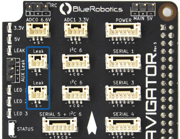
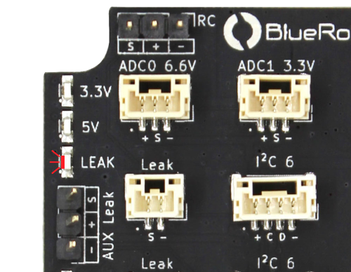
Leak Detection
The Navigator has a built-in leak detection circuit for vehicles where water ingress is a possibility. Two leak detection probes can be connected directly to the Navigator using the Leak ports.
| Leak | ||
|---|---|---|
| Connector Pinout | 1 - Signal 2 - GND | 5 V Pull-up GND |
| JST GH Connector Type | BM02B-GHS-TBT(LF)(SN)(N) | |
| Mating JST GH Plug and Crimp Pins | GHR-02V-S (housing) SSHL-002T-P0.2 (pin) |
|
If a leak is detected by one of the probes, the LEAK indicator LED will illuminate red and a failsafe warning will be triggered in software.
If additional probes are required, an SOS Leak Sensor can be connected to the AUX Leak header.
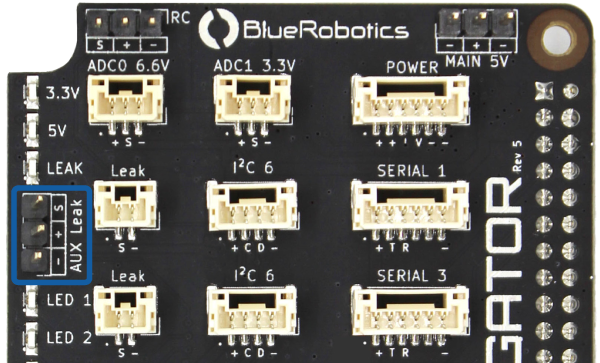
| AUX Leak | ||
|---|---|---|
| Connector Pinout | 1 - Signal 2 - VCC 3 - GND | 5 V 5 V GND |
| Connector Type | 3 position 0.1″ pitch male header pins | |
| Mating Connector | 3 position 0.1″ pitch female header | |
Replacement leak probes are available here.
RGB LED Header
The RGB LED header supports connecting an addressable LEDs strips based on WS2812 or SK6812 LEDs, also known as “NeoPixels”. The RGB LED connector is powered by AUX 5V power input.
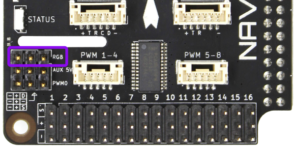
| RGB | ||
|---|---|---|
| Connector Pinout | 1 - Data 2 - V (Aux) 3 - GND | 5 V V (Aux) GND |
| Connector Type | 3 position 0.1″ pitch male header pins | |
| Mating Connector | 3 position 0.1″ pitch female header | |
PWM0/Fan Header
The PWM0 connector is intended for controlling a fan for cooling. Unlike the servo rail PWM 1–16 connectors, which are connected to the PCA9685 PWM driver, the PWM pin on this connector is connected directly to the Raspberry Pi 4 SOC GPIO18 pin, which can function as the Raspberry Pi SOC PWM0 output signal. This pin may also be used as a general purpose input/output or PWM function with user application code.
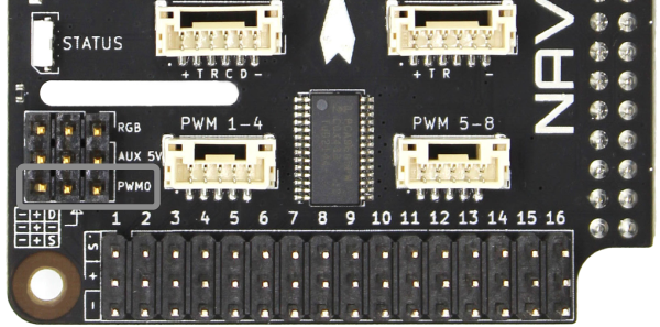
| PWM0 | ||
|---|---|---|
| Connector Pinout | 1 - PWM0 2 - V (Aux) 3 - GND | 3.3 V V (Aux) GND |
| Connector Type | 3 position 0.1″ pitch male header pins | |
| Mating Connector | 3 position 0.1″ pitch female header | |
Camera
BlueOS supports USB cameras with H.264 encoded video streams such as the Blue Robotics Low-Light HD USB Camera. Connect the USB camera to one of the Raspberry Pi USB ports and BlueOS will auto-configure the camera stream the first time it starts up. The camera and video stream configuration can be managed from the BlueOS web interface. Please visit the BlueOS documentation for more information.
Next Steps
To continue with the setup process, proceed to the Navigator Software Setup guide.