
Blue Robotics Connector Standard (Beta)
By Rusty
This guide documents and explains our standard pin configurations for various connectors. This standard is intended to maximize compatibility between various devices.
Background
This standard is originally based on the Pixhawk Connector Standard (formerly known as the Dronecode Mini Connector Standard), which was developed to help standardize the connectors used on drone flight controllers. We have added additional types of connections that are frequently used in subsea devices such as RS485. We’ve also added pin configurations for higher-power devices and those connected through typical subsea connectors such as the “MCIL” type wet-mateable rubber-molded connectors.
Connector Types and Pin Identification
JST GH Series
The JST GH Series connectors are the primary connector recommended for use on PCBs. They are compact, easy to plug and unplug, and are affordable. These are specified by the Pixhawk Connector Standard and are used on most ArduPilot and PX4 flight controller boards. Note that these are not used on the original Pixhawk flight controller but we do use them on the Navigator.
Pre-crimped Leads: Digikey Pre-crimped JST GH LeadsCrimp Pin: SSHL-002T-P0.2
Recommended Crimper: YRS-1590
Housings: JST GH housings on Digikey
Eagle Footprint Library: BlueRobotics-JST-GH (.lbr)
Voltage Rating: 50 V
Max Current per Pin: 1.0 A
Pin Identification:
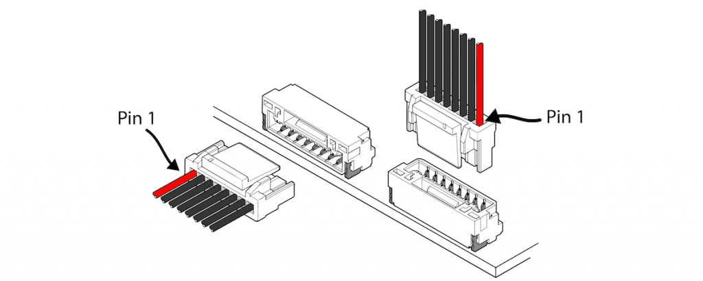
JST GH Connector Pin Identification
0.1" (2.54mm) Header Pins
0.1″ header pins are a staple of open source electronics designs and used in many places in our product line including the servo headers for the Basic ESC, Newton Gripper, and Lumen Lights as well as on various interface boards like the Fathom-S. Many of our designs expose 0.1″ header pins even if they are not actively used.
Pre-crimped Leads: Pololu Pre-crimped 0.1″ Header LeadsCrimp Pin: Male, Female
Housings Housings
Eagle Footprint Library: pinhead (.lbr)
Voltage Rating: 250 V
Max Current per Pin: 3.0 A
Pin Identification:
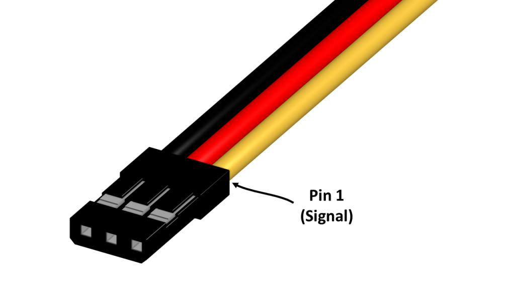
0.1in Header Connector Pin Identification
High Power Anti-Spark Connectors
XT90(-S) and QS8-S connectors are frequently used for high-current applications, such as providing vehicle power. The built in anti-spark technology (-S) is particularly important for high voltage connections, and the Nylon sheaths and gold-plated pins allow for safe and reliable usage at high currents. These connectors are used on our batteries, depending on the voltage and discharge-current capacities.
Flame Retardant Rating: UL94 V0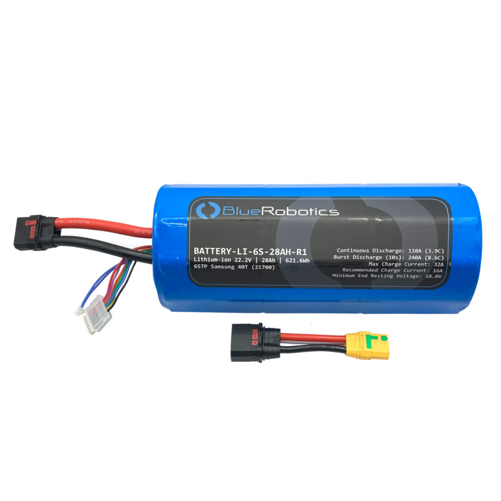
QS8-S (black) and XT90-S (yellow) Connectors
Micro Circular (MC) Wet-Mateable Series
The Micro Circular (MC) Wet-Mateable Series connectors are the industry standard connector used in subsea connections. The connectors are rubber molded and must be greased before being plugged in. There are multiple manufacturers of the MC Series and they should all be interchangeable between manufacturers. Please note that Blue Robotics does not use MC type connectors on any current products but they are included here for reference because of their commonality.
Depth Rating: 8,000 mVoltage Rating: 300 V
Max Current per Pin: 10 A for 2, 3, 4 pin versions, 5 A for 6, 8 pin versions (max 20A per connector)
*All specifications shown are from SubConn documentation. Other brands may vary.
Pin Identification: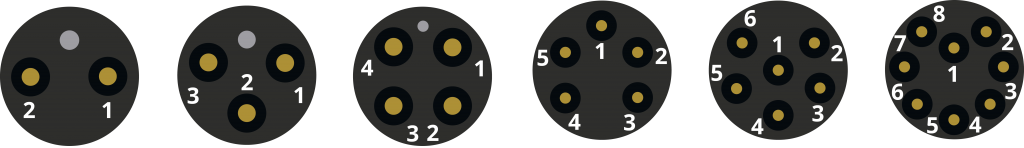
MC wet-mateable connector pin identification (from male pin side).
Current manufacturers include:
- SubConn (MacArtney)
- Seacon
- Birns Aquamate
- Teledyne Impulse Splash Mate Series
- Eaton (formerly Burton)
- SeaView Systems
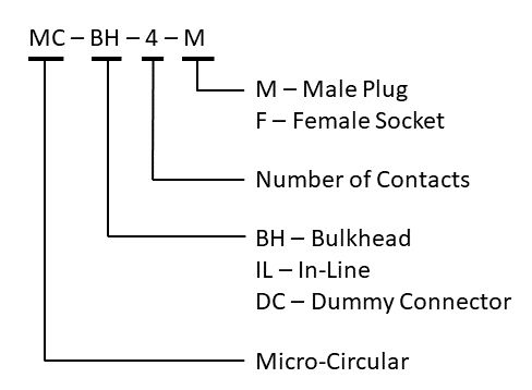
MC Series Designation System
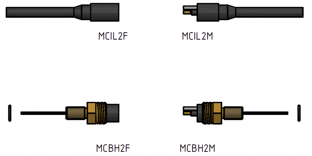
MC Series Example Connectors
Superseded Connector Types
These connectors were previously part of the standard, but are no longer recommended for new designs.
Hirose DF13 Series (superseded)
Hirose DF13 connectors are used on many older flight controllers, including the original Pixhawk flight controller board. Because of this, several of Blue Robotics’ products came by default with DF13 connectors. Modern flight controllers typically use JST-GH connectors instead, and we do not recommend DF13 connectors for new designs. There is an adaptor for interfacing with older DF13 products.
Pre-crimped Leads: Digikey Pre-crimped DF13 LeadsCrimp Pin: DF13-2630SCF
Housings: DF13 housings on Digikey
Eagle Footprint Library: con-hirose-df13 (.lbr)
Voltage Rating: 150 V
Max Current per Pin: 1.0 A
Host and Device Terminology
The Blue Robotics Connector Standard refers to devices as Host and Device. This distinction differentiates some of the connector pinouts, such as the serial port pinout. It’s also important to differentiate between the connector polarities used on the devices. Proper connector polarity ensures safety between devices and ensures that powered electrical pins are never exposed to the user.
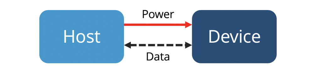
Host and device terminology as used in the connector standard.
Serial Port
This is the standard pinout for a TTL serial port. There are separate Host and Device versions so that a straight-thru cable can be used to connect devices. CTS (clear to send) and RTS (request to send) flow control signals are optional and should be left floating if they are not used.
Host Serial Port
This pinout is used for the host (computer, flight controller, master device, etc.).
Wire to board connections:
| Recommended Connector | Pin # | Signal | Voltage | Recommended Wire Color |
|---|---|---|---|---|
| JST GH (6 position) Part #: BM06B-GHS-TBT(LF)(SN)(N) SM06B-GHS-TB(LF)(SN) | 1 | VCC | 5v | Red |
| 2 | TX (out) | 3.3v | Green | |
| 3 | RX (in) | 3.3v | White | |
| 4 | CTS (in) | 3.3v | ||
| 5 | RTS (out) | 3.3v | ||
| 6 | GND | GND | Black |
Subsea connections:
| Recommended Connector | Pin # | Signal | Voltage |
|---|---|---|---|
| Subconn Micro Circular (6 position) Part #: MCBH-6F MCIL-6F | 1 | V+ (power) | 12-18v |
| 2 | VCC | 5v | |
| 3 | TX (out) | 3.3v | |
| 4 | RX (in) | 3.3v | |
| 5 | GND | GND | |
| 6 | GND (power) | GND |
Device Serial Port
This pinout is used for the device (sensor, actuator, controller, etc.). The RX/TX colors are flipped relative to the Host version so that a straight-thru cable can be used to connect the Host to the Device.
Wire to board connections:
| Recommended Connector | Pin # | Signal | Voltage | Recommended Wire Color |
|---|---|---|---|---|
| JST GH (6 position) Part #: BM06B-GHS-TBT(LF)(SN)(N) SM06B-GHS-TB(LF)(SN) | 1 | VCC | 5v | Red |
| 2 | RX (in) | 3.3v | Green | |
| 3 | TX (out) | 3.3v | White | |
| 4 | RTS (out) | 3.3v | ||
| 5 | CTS (in) | 3.3v | ||
| 6 | GND | GND | Black |
Subsea connections:
| Recommended Connector | Pin # | Signal | Voltage |
|---|---|---|---|
| Subconn Micro Circular (6 position) Part #: MCBH-6M MCIL-6M | 1 | V+ (power) | 12-18v |
| 2 | VCC | 5v | |
| 3 | RX (in) | 3.3v | |
| 4 | TX (out) | 3.3v | |
| 5 | GND | GND | |
| 6 | GND (power) | GND |
RS485
This pinout is for an RS485 serial port. The pin names for RS485 are often confusing and mixed up so the pin names are defined in multiple ways. Be sure to triple check for your application!
Wire to board connections:
| Recommended Connector | Pin # | Signal | Voltage | Recommended Wire Colors |
|---|---|---|---|---|
| JST GH (4 position) Part #: BM04B-GHS-TBT(LF)(SN)(N) SM04B-GHS-TB(LF)(SN) | 1 | VCC | 5v | Red |
| 2 | A (non-inverting) | 5v | White | |
| 3 | B (inverting) | 5v | Green | |
| 4 | GND | GND | Black |
Subsea connections:
| Recommended Connector | Pin # | Signal | Voltage |
|---|---|---|---|
| Subconn Micro Circular (6 position) Part #: Host: MCBH-6F, MCIL-6F Device: MCBH-6M, MCIL-6M | 1 | V+ (power) | 12-18v |
| 2 | VCC | 5v | |
| 3 | A (non-inverting) | 5v | |
| 4 | B (inverting) | 5v | |
| 5 | GND | GND | |
| 6 | GND (power) | GND |
CAN
This is for CAN bus connections. Currently, CAN bus is not used in any Blue Robotics products but is typically a good choice for vehicle system communication and is used on many drone products. The standard pinout here matches the Pixhawk Connector Standard.
Wire to board connections:
| Recommended Connector | Pin # | Signal | Voltage | Recommended Wire Colors |
|---|---|---|---|---|
| JST GH (4 position) Part #: BM04B-GHS-TBT(LF)(SN)(N) SM04B-GHS-TB(LF)(SN) | 1 | VCC | 5v | Red |
| 2 | CAN H | 5v | White | |
| 3 | CAN L | 5v | Green | |
| 4 | GND | GND | Black |
Subsea connections:
| Recommended Connector | Pin # | Signal | Voltage |
|---|---|---|---|
| Subconn Micro Circular (6 position) Part #: Host: MCBH-6F, MCIL-6F Device: MCBH-6M, MCIL-6M | 1 | V+ (power) | 12-18v |
| 2 | VCC | 5v | |
| 3 | CAN H | 5v | |
| 4 | CAN L | 5v | |
| 5 | GND | GND | |
| 6 | GND (power) | GND |
USB
This pinout is the opposite of that used on the Pixhawk DF13 connector but matches up with standard USB, which we determined to be more important. The Pixhawk Connector Standard does not officially define a USB standard, so this may not be followed by other flight controllers.
Wire to board connections:
| Recommended Connector | Pin # | Signal | Voltage | Recommended Wire Colors |
|---|---|---|---|---|
| JST GH (4 position) Part #: BM04B-GHS-TBT(LF)(SN)(N) SM04B-GHS-TB(LF)(SN) | 1 | VCC | 5v | Red |
| 2 | D- | 5v | White | |
| 3 | D+ | 5v | Green | |
| 4 | GND | GND | Black |
Subsea connections:
| Recommended Connector | Pin # | Signal | Voltage |
|---|---|---|---|
| Subconn Micro Circular (6 position) Part #: Host: MCBH-6F, MCIL-6F Device: MCBH-6M, MCIL-6M | 1 | V+ (power) | 12-18v |
| 2 | VCC | 5v | |
| 3 | D- | 5v | |
| 4 | D+ | 5v | |
| 5 | GND | GND | |
| 6 | GND (power) | GND |
I2C
This pinout is for I2C communication and matches the Pixhawk Connector Standard standard exactly. We do not recommend using I2C for longer connections so no external version is provided.
Wire to board connections:
| Recommended Connector | Pin # | Signal | Voltage | Recommended Wire Colors |
|---|---|---|---|---|
| JST GH (4 position) Part #: BM04B-GHS-TBT(LF)(SN)(N) SM04B-GHS-TB(LF)(SN) | 1 | VCC | 5v | Red |
| 2 | SCL | 3.3v | Green | |
| 3 | SDA | 3.3v | White | |
| 4 | GND | GND | Black |
Ethernet 10/100
The pin orders are set up so that the same wires can be used for other four-pin connections and maintain the same colors on pins 2 and 3.
Wire to board connections:
| Recommended Connector | Pin # | Signal | Recommended Wire Colors |
|---|---|---|---|
| JST GH (4 position) Part #: BM04B-GHS-TBT(LF)(SN)(N) SM04B-GHS-TB(LF)(SN) | 1 | TX+ | White/orange |
| 2 | RX+ | White/green | |
| 3 | RX- | Green | |
| 4 | TX- | Orange |
Subsea connections:
| Recommended Connector | Pin # | Signal | Recommended Wire Colors |
|---|---|---|---|
| Subconn Micro Circular (6 position) Part #: Host: MCBH-6F, MCIL-6F Device: MCBH-6M, MCIL-6M | 1 | V+ (power, 12-18v) | Red |
| 2 | TX+ | White/orange | |
| 3 | RX+ | White/green | |
| 4 | RX- | Green | |
| 5 | TX- | Orange | |
| 6 | GND (power) | Black |
Power Only / LED Indicator
This is used for the LED indicator and other power-only devices.
Wire to board connections:
| Recommended Connector | Pin # | Signal | Voltage | Recommended Wire Colors |
|---|---|---|---|---|
| JST GH (2 position) Part #: BM02B-GHS-TBT(LF)(SN)(N) SM02B-GHS-TB(LF)(SN) | 1 | VCC | Red | |
| 2 | GND | GND | Black |
Tether
This pinout is used on all tether cables. It is compatible with tethers consisting of twisted pairs, up to four twisted pairs. For cables with less than four twisted pairs, the later wires are ignored. For all connections, we recommend using 8 pin connectors, regardless of how many twisted wire pairs are actually used. This will allow for future upgrades and expansion, if necessary.
Sealed compartment inline connections:
| Recommended Connector | Pin # | Wire | Wire Colors |
|---|---|---|---|
0.1″ Header (3 position with positions 1 and 3 populated)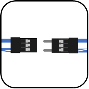 | 1 | Solid color wire | Blue Orange Green Brown |
| 2 | Empty | ||
| 3 | Striped color wire | White/Blue White/Orange White/Green White/Brown |
Subsea and topside bulkhead connections:
| Recommended Connector | Pin # | Pair # | Wire Color | Typical Signal |
|---|---|---|---|---|
| Subconn Micro Circular and Binder 770 (8 position) Part #: Host: Binder 770 Bulkhead Device (ROV Bulkhead): MCBH-8M Device (tether): Binder 770 Plug (topside) and MCIL-8F (ROV side) | 1 | Pair 1 | Blue | Homeplug D- |
| 2 | White/Blue | Homeplug D+ | ||
| 3 | Pair 2 | Orange | ||
| 4 | White/Orange | |||
| 5 | Pair 3 | Green | ||
| 6 | White/Green | |||
| 7 | Pair 4 | Brown | ||
| 8 | White/Brown |
Thruster or Motor
This pinout is used for thrusters and other three-phase brushless motors. Note that Blue Robotics’ thrusters do not currently enforce consistent pin ordering so two motors may spin in opposite directions for a given input signal.
| Recommended Connector | Pin # | Signal | Recommended Wire Colors |
|---|---|---|---|
Part #: Host: MCBH-3F, MCIL-3F Device (thruster): MCIL-3M | 1 | Phase A | Blue |
| 2 | Phase B | Green | |
| 3 | Phase C | White |
Servo or PWM Signal Devices
This pinout is used for standard RC-type servos or any other device that is controlled with a servo-style PWM pulse, such as the Lumen lights or Newton Gripper. Four pins are used on the subsea version to enable future devices with two independent signals as well as Y-split connections to two devices.
Wire to board connections:
| Recommended Connector | Pin # | Signal | Voltage | Recommended Wire Colors |
|---|---|---|---|---|
0.1″ Header (3 position female)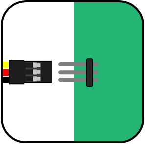 | 1 | PWM Signal | 5v | Yellow |
| 2 | 5v (or empty) | 5v | Red | |
| 3 | GND | GND | Black |
Subsea connections:
| Recommended Connector | Pin # | Signal | Voltage | Recommended Wire Colors |
|---|---|---|---|---|
| Subconn Micro Circular (4 position) Part #: Host: MCBH-4F, MCIL-4F Device (servo): MCBH-4M, MCIL-4M | 1 | V+ (power) | 5v-18v | Red |
| 2 | PWM Signal #1 | 5v | ||
| 3 | PWM Signal #2 | 5v | ||
| 4 | GND | GND | Black |
Authors

Rusty
Rusty is the founder and CEO of Blue Robotics. His background is in engineering but he likes to be involved in everything at Blue Robotics!