
Understanding and Using Scanning Sonars
Introduction
Acoustic imagery and returns from scanning sonars can be difficult to understand. This guide will help in interpreting displayed sonar images and some best practices and techniques for when they are mounted on ROVs. Although the Ping360 and BlueROV2 are used in the illustrations, the concepts are general enough to be applied to any mechanical scanning sonar and ROV combination.
References
- Blondel, Philippe. 2009. The Handbook of Sidescan Sonar. Chichester, UK: Praxis Publishing Ltd.
- blueprint subsea. 2017. “Oculus M-Series User Manual (English).” Oculus Multibeam Sonar Support. Last modified March 30th, 2017. https://www.blueprintsubsea.com/sys/download.php?Id=oculus_mseries_manual_en.
- Christ, Robert, and Robert Wernli Sr. 2014. The ROV Manual: A User Guide for Remotely Operated Vehicles. Second Edition. Oxford: Butterworth-Heinemann.
- DeepVision AB. 2016. “3.3 Side Scan Sonar at Sea.” User Guides. http://deepvision.se/wp-content/uploads/2017/01/3.3-DeepView-SideScanSonaratSea.pdf.
Operating Principles
Scanning SONARs (SOund Navigation And Ranging) are a type of active sonar which operates by transmitting pulses of sound into the water and recording the echoes that are returned as each sound pulse is reflected off objects in front of it.
Scanning sonars are further defined by having a “fan” shaped acoustic beam with a wide vertical beam and a narrow horizontal beam for obtaining acoustic cross-sections of the environment and then displaying the cross sections as a single image on a viewer.
Speed Of Sound
By combining the known speed of sound in water with the time the echoes were received, the sonar can calculate the distance the sound has traveled. The equation for determining distance acoustically is:
distance = known speed of sound in water * (measured time for echo to return / 2)
Therefore, major differences in speed of sound can affect accurate ranges to targets.
Typically, the speed of sound in saltwater is about 1500m/s, but this can vary depending on the water temperature, salinity and sonar operating depth. Speed of sound calculators can be used to get more accurate values for different operating conditions.
Although scanning sonars do not have the capability to automatically calculate the speed of sound, the value can be changed in the viewer for the right conditions.

Speed of Sound setting in Ping-Viewer
Target Reflectivity
Targets with material densities very different from water (such as gas, rock, concrete or metal) will be very reflective and have strong echoes. Echoes from materials like mud, silt, sand and plants will have weaker echoes as they either have a similar density to water or absorb acoustic energy.
The strength of the echo is displayed on the viewer as a bright indication from the color palette.
In typical color palettes, darker colors are used for weak echoes, while brighter colors are used for stronger echoes.
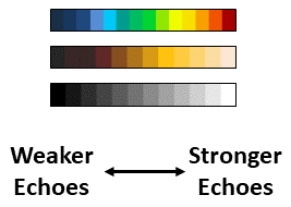
Typical scanning sonar color palettes
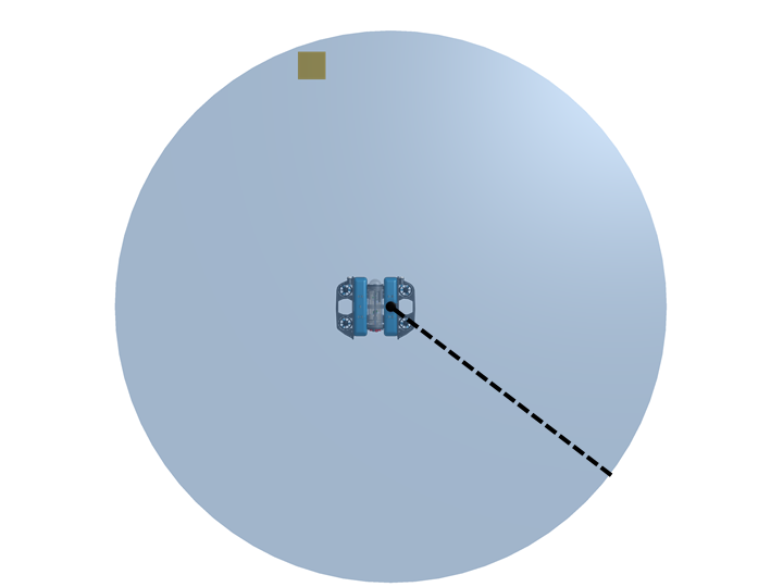
The sonar image below shows how a vertically suspended braided rope appears brighter than the surrounding water because it has a different density (less) than seawater.

ROV view of a vertical rope in low-visibility water
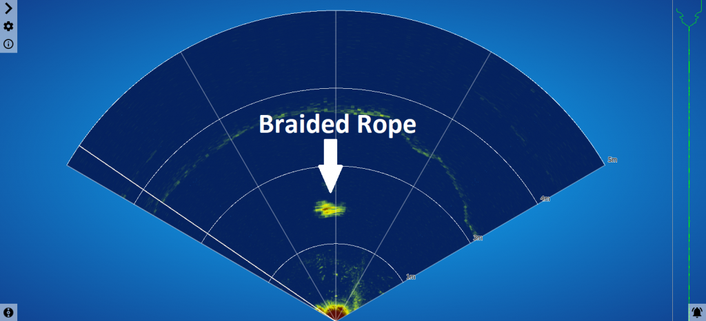
Sector scan of the rope (top-down perspective showing the rope as a dot)
Acoustic Beam Patterns
When imagining how scanning sonars work acoustically, they are often compared to shining a flashlight in a dark area. Only the area illuminated by the flashlight’s beam is visible to the user, the rest remaining dark.
In comparison to a beam of light, scanning sonars have an acoustic beam with a fixed width and height called Horizontal and Vertical Beam Patterns. It will be this acoustic beam that “illuminates” the surrounding underwater area with acoustic energy instead of visible light energy.
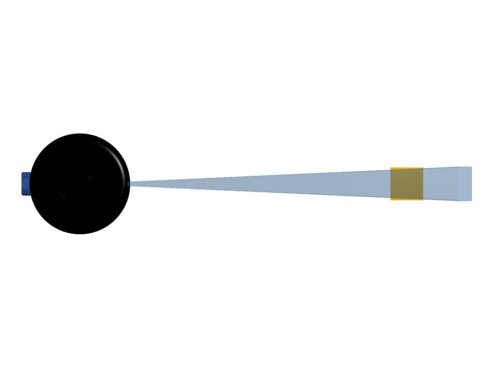
Scanning sonars typically have a wide vertical beam and a narrow horizontal beam to produce a narrow “slice” in front of the transducer.
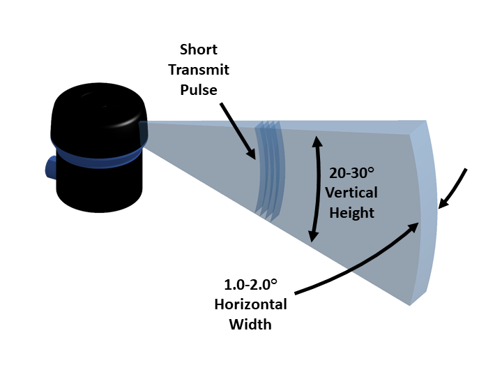
Typical fan shaped beam used on scanning sonars
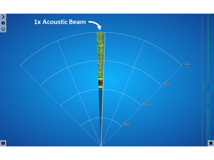
Sonar display showing one beam 'slice'
To “draw” an image or locate targets, the transducer head inside the scanning sonar mechanically rotates via a stepper motor and moves the head in an arc to build up the “slices” into an image on the the display software.
Think of the flashlight analogy with a camera taking snapshots as the flashlight beam is swept around an area. The user won’t be able to see everything at once with the narrow beam of the flashlight, but building up the images from the camera will allow the user to see the entire area as a single image, as a panoramic image would do.
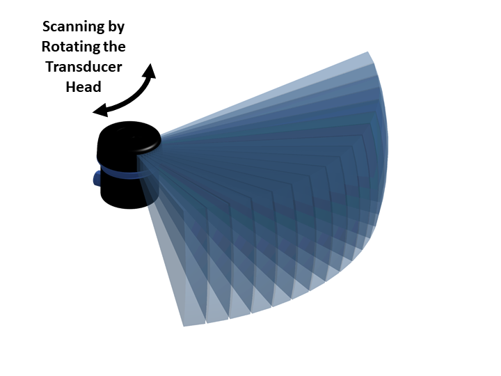
Mechanically rotating the sonar transducer
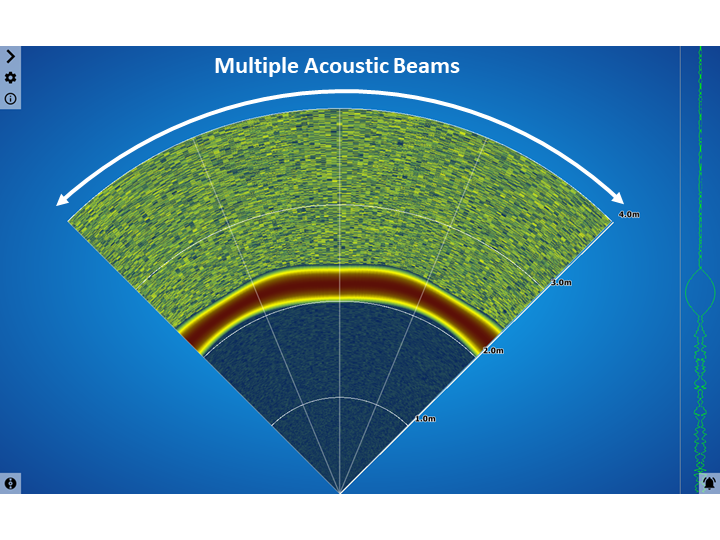
Multiple sonar beams built up to form a 'scan'
Target Visibility
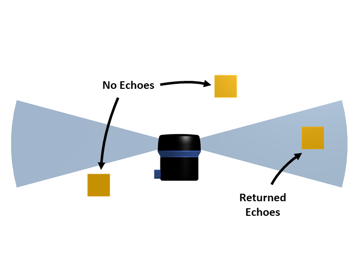
Targets within the sonar horizontal and vertical beam pattern will be acoustically “illuminated” and their echoes will be reflected back to the sonar to be received and interpreted as an image.
Targets outside of the beam pattern (above, below our outside the horizontal range) will not be shown on the viewer display.
Vertical Arrival Angle and Slant Range
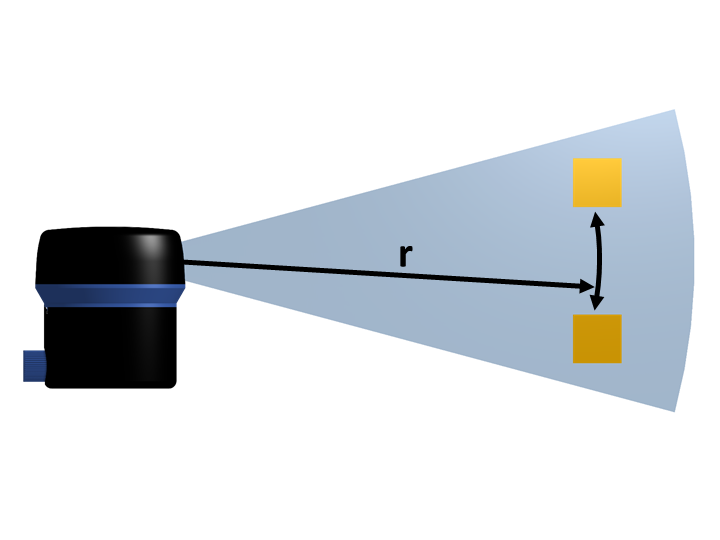
Scanning sonars are unable to differentiate between objects with the same vertical arrival angle, also known as the “slant range” (Blondel 2009, 15 and 37-38). Meaning, if two targets are in front of the sonar at the same range vertically above each other, the sonar will show both these as a single result made up from a combination of their echoes.
Viewing the Seabed
Using the analogy of the flashlight beam, and understanding that scanning sonars can’t differentiate targets at different altitudes, the sonar images shown on the display can then be thought of as a “top-down” view of the area.
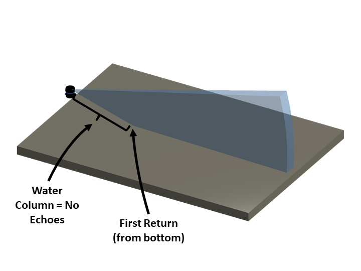
Fan shaped sonar beam intersects with a flat bottom
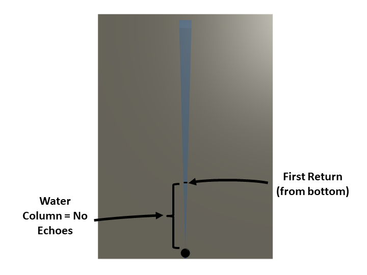
Resulting top-down view as shown in the display
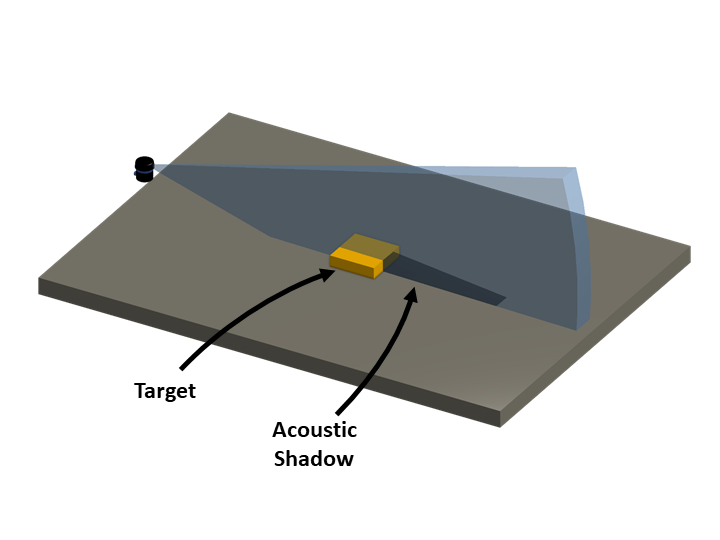
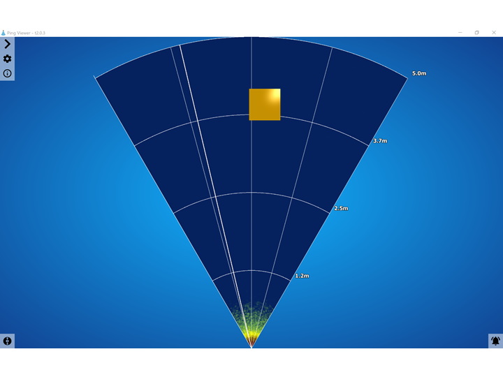
Fan shaped sonar beam intersects with a flat bottom and a target
Resulting top-down view as shown in the display
Bottom Visibility
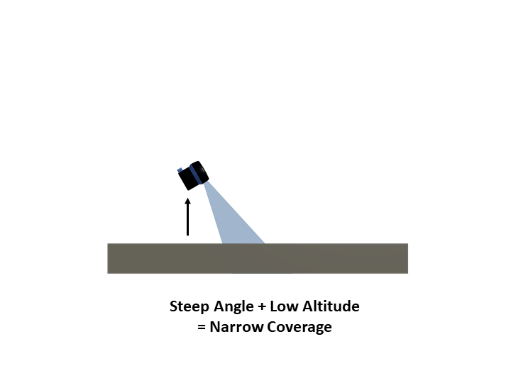
For users searching the sea bottom and knowing that signal strength decreases at further ranges, scanning sonars can be mounted at angles so different amounts of the seabed can be illuminated and visible on the display.
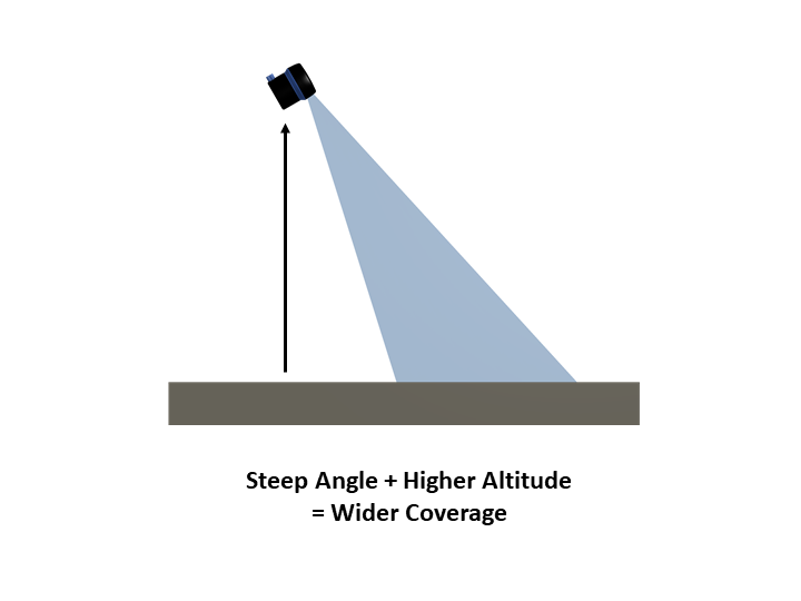
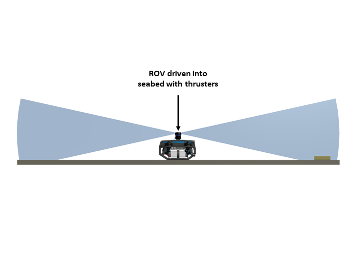
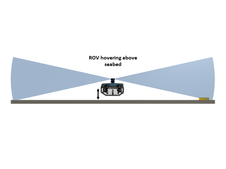
If the sonar has a low altitude and angled downwards at a steep angle, then only a narrow portion of the total area will be shown. By gaining altitude, the sonar can illuminate a wider swath of the sea bottom.
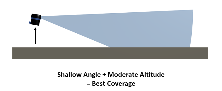
When operators are searching for targets on the sea bottom, the best use of the sonar comes from balancing the altitude above the sea bottom with the sonar angled down slightly. This will give the longest bottom imaging range for the sonar’s signal strength.
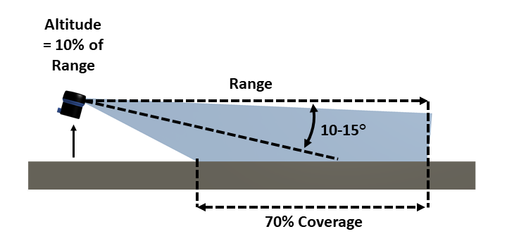
10% Rule
As a general rule, a scanning sonar (both sidescan and mechanically scanning) can achieve around 70% seabed coverage of a given area if it has a 10-15° down angle and an altitude of 10% of the operating range (DeepVision AB, 12)(blueprint subsea, 17). For example, at a 10m range, the sonar should have an altitude of 1m above the sea bottom. At a 20m range, the sonar should have an altitude of 2m.
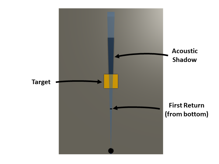
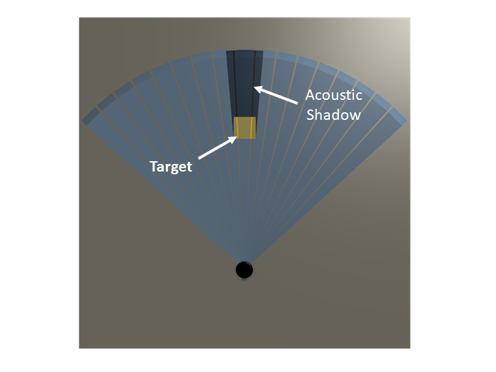
Acoustic Shadows
The flashlight analogy can continue to be used when the sonar locates a target on the sea bottom in order to help determine the height, shape and orientation. An “acoustic shadow” will be shown behind an illuminated target in the same way that a “visible light shadow” will be visible behind an object illuminated with a flashlight.
Altitude
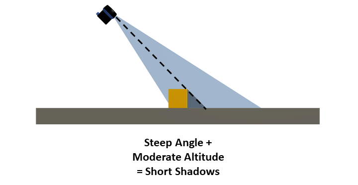
If the sonar has a relatively high altitude and steep down angle then acoustic shadows will be short. Short acoustic shadows can sometimes be hard to see, and make assessment of the target more difficult.
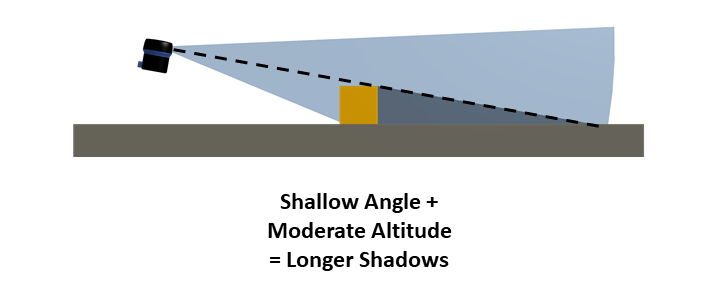
If the sonar has an altitude closer to the bottom and a shallower down angle, acoustic shadows cast by targets will be longer allowing for easier interpretation.
Distance
Acoustic shadows cast by targets that are far away will be relatively narrow based on angular geometry of the sonar beam. Acoustic shadow width will increase as the sonar is moved closer to the target. With wider shadows, it may be possible that additional targets with in the acoustic shadow may not be seen as there is no acoustic signal illuminating them.
Narrow shadow produced by a target further away
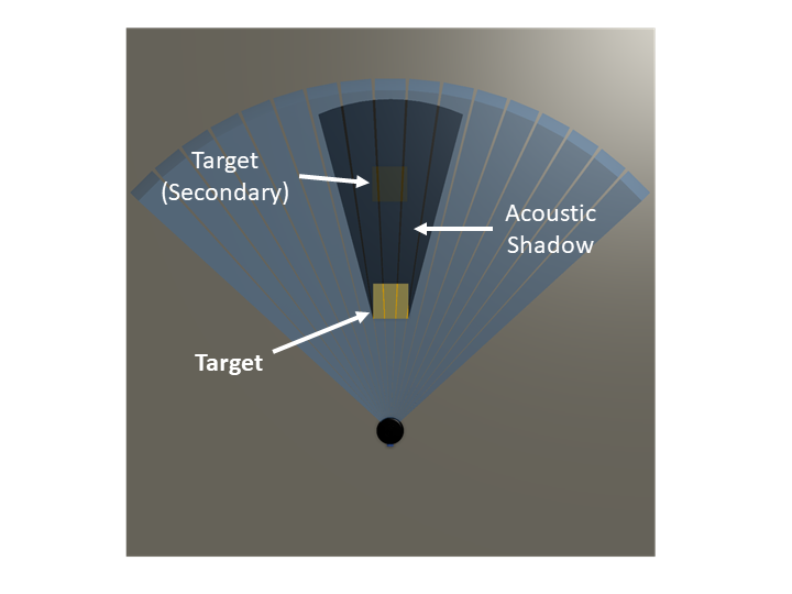
Wider shadow produced by a target closer to the sonar and obscuring the secondary target
Understanding Echoes
As illustrated in the previous sections, targets are illuminated from the side by scanning sonars. Therefore, only the edges or surfaces closest to the sonar will be illuminated.
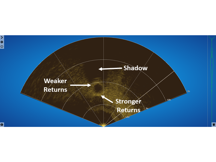
Surfaces of targets that are perpendicular to the sonar will yield the strongest returned echoes, while surfaces at other angles will cause the acoustic waves to reflect away from the sonar, yielding weaker returns.
Echoes from Targets
The sonar image below of a tire resting on the bottom shows how the edge of the tire closest to the sonar has the brightest echoes and the face of the tire that is pointing upwards has weaker returns.
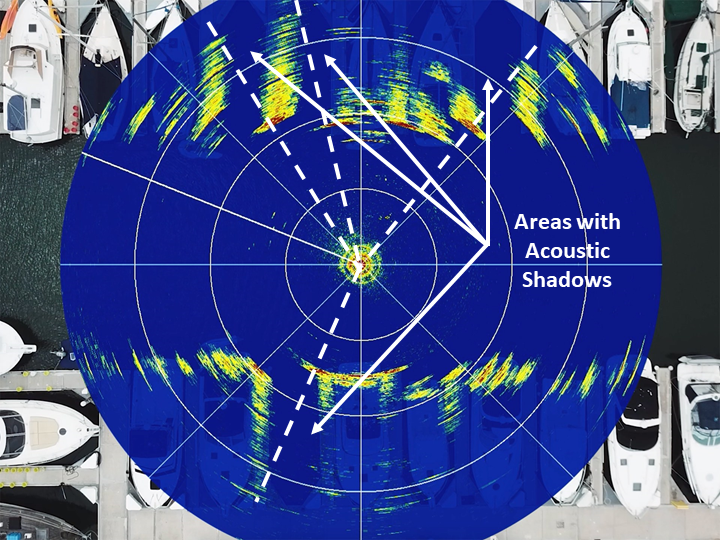
Echoes from the Environment
These same acoustic principles also apply to larger environments. The figure below shows various dock fingers and boat hulls in the water. The bright returns from show features within “line of sight” from the sonar. Areas obscured behind the returns are shown as shadows or areas of “no returns.”
ROV Navigation with a Scanning Sonar
Even with the unique-ness of acoustic image interpretation, scanning sonars can be an important navigation tool when mounted to an ROV. Without a scanning sonar, the ROV pilot must rely on visually interpreting targets and features through the camera. In low visibility conditions, visibility may be severely restricted and the range may be less than a meter.
Scanning sonars increase the range at which targets may be located. Instead of flying above the seabed and visually looking for targets, it is often more useful to either remain stationary or sit on the bottom and completely scan the surrounding area. The pilot can get a relative bearing to natural or man-made features, potential targets, or eliminate areas that are not of interest.
Due to the low mass of small ROVs, unintended movement in either the vertical or horizontal plane is common when operating in the water column. For scanning sonars, an image is generated as the transducer head is rotated (or stepped) about its center-point axis. If the ROV is moved either through pilot input or environmental factors before the image is allowed to completely generate, “image smear” will occur. This distorts the image plot and will make the image nearly impossible to interpret.
In these instances it may be better to either gently sit the ROV on the bottom or narrow the sector scan so that the refresh rate is faster and rotate the ROV about its axis.
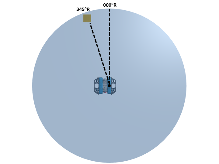
Relative Bearing
It is important to note that when looking at a sonar viewer angles to a target are considered to be “relative bearings” where the target is read as a clockwise angle from straight ahead (000°R). More information on relative bearings can be found in this Wikipedia article.
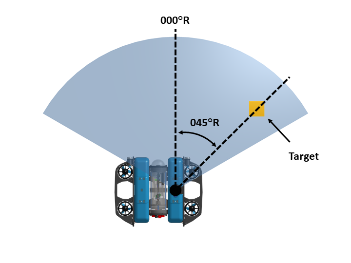
Relative bearing of a target from an ROV
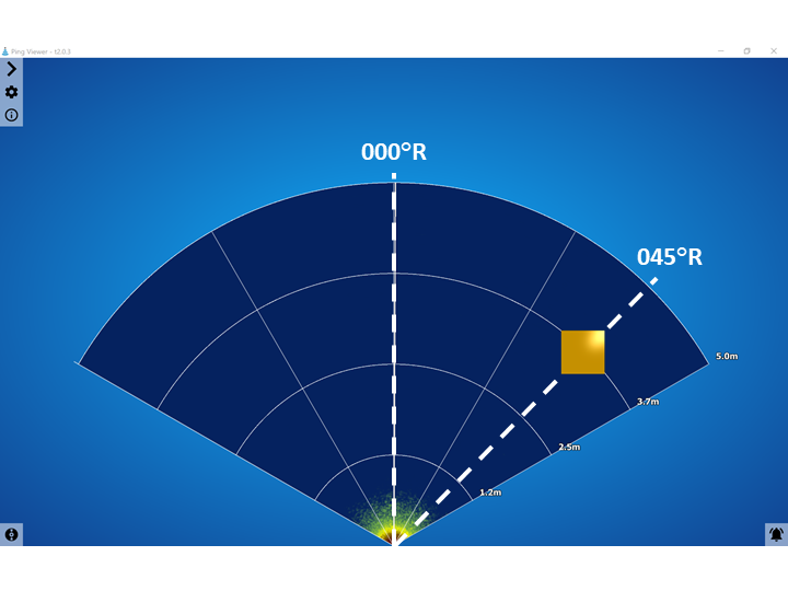
Relative Bearing as shown on the sonar viewer
Polar Scan
Any scan that is a continuous 360 degrees is known as a “polar scan.”
Polar scans are useful for gaining situational awareness all around the ROV in low visibility conditions. Cameras typically have a narrow field of view (~90°) and are unable to look around or to the side unless on a panable gimbal. A polar scan is useful for understanding what may be to the side or behind an ROV.
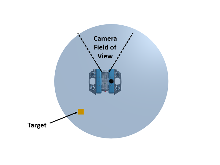
Polar Scan locating a target behind an ROV
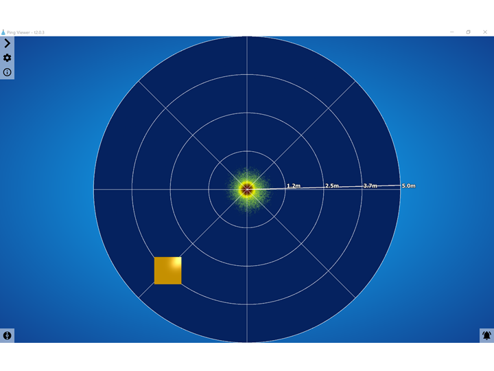
Polar scan as shown on a viewer
Sector Scan
Any sonar scan less than 360 degrees is known as a “sector scan.”
Sector scans are useful for increasing the scanning refresh rate while imaging a target or keeping track of a target while moving. The disadvantage of a sector scan is the loss of imaging to the sides or behind the ROV.
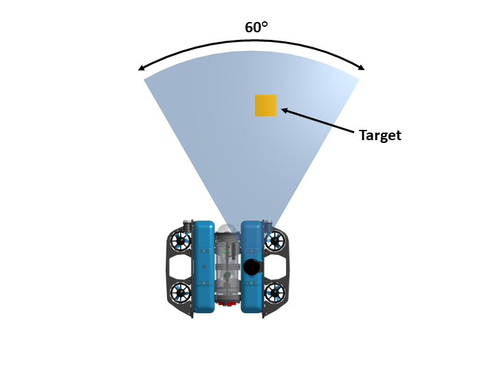
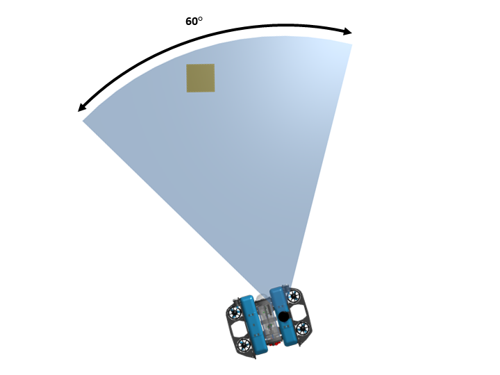
Scan width reduced to 60 Degrees
Sector scan shown on a sonar display
Locating Targets with ROV-mounted Scanning Sonar
Locating targets either on the seabed or water column is another use for a scanning sonar other than for navigation purposes.
Learning how to use a scanning sonar for finding targets will take some practice as smaller targets are much harder to locate and identify than larger ones.
The key is to maneuver and turn slowly to allow for the time it takes for new images to be generated.
1. Place ROV in a very stable position on or near the bottom.
2. Allow generation of a 360 degree Polar Scan.
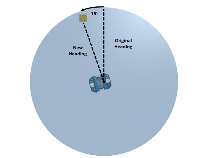
3. Identify the relative bearing of the target.
4. Turn the ROV to align the target at a zero relative bearing.
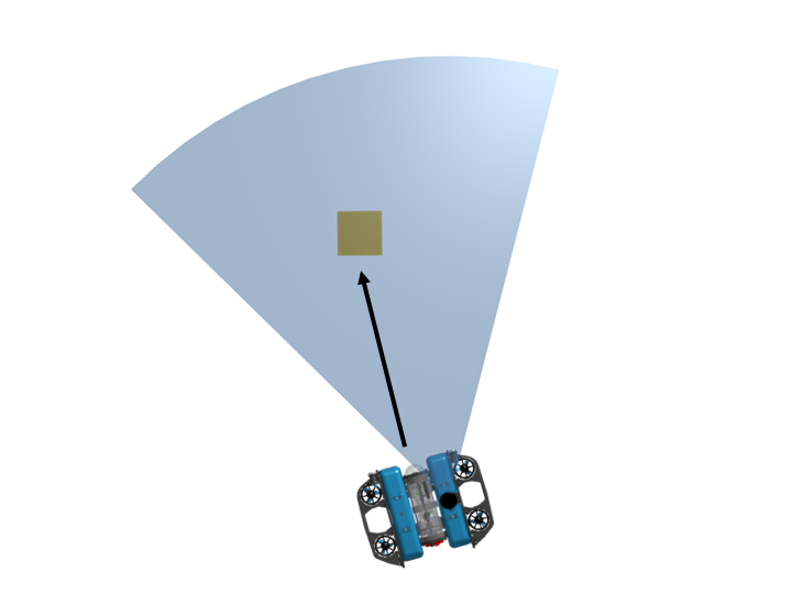
5. Narrow the sector scan of the sonar to approximately 60-90 degrees to take advantage of the faster refresh rate.
6. Maintain contact with the target on sonar as the vehicle is driven forward.
Other Techniques
There are a lot of applications for scanning sonars! If you happen to know of more or are doing a cool project with one, please feel free to write a quick post in our forums and let us know about your experiences.