
BlueROV2 Assembly
Guide Versions
This assembly guide is for the R4 version of the BlueROV2. There are three versions of the BlueROV2 assembly guide that each reflect the major revisions to the BlueROV2 hardware and assembly process. Please ensure you are viewing the correct assembly guide for the revision of BlueROV2 you have. The revision number for your BlueROV2 can be found in the product SKU in your order information (example: “BLUEROV2-M-R4-RP”).
R4 Version (with Navigator Flight Controller, sold from 7 June 2022 to present): continue using this guide
R3 Version (with Pixhawk autopilot and dual power cables, sold from 14 September 2021 to 6 June 2022): use the BlueROV2 R3 Assembly Guide
R1 and R2 Version (with Pixhawk autopilot and single power cable, sold from 21 June 2016 to 13 September 2021): use the BlueROV2 R1 and R2 Assembly Guide
Other BlueROV2 Guides in this Series
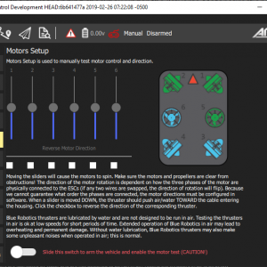
BlueROV2 Software Setup
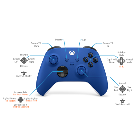
BlueROV2 Operation
Introduction
The BlueROV2 kit comes almost ready to dive. The assembly can be completed with basic hand tools, no soldering or potting is required. We have included a few of the tools to make assembly and regular use as easy as possible.
The assembly process varies based on whether you are assembling a standard BlueROV2 or a BlueROV2 with the optional BlueROV2 Heavy Configuration Retrofit Kit. If you are assembling a standard BlueROV2 only, select the “BlueROV2” button below. If you are assembling a new BlueROV2 with an optional Heavy Kit, select the “BlueROV2 Heavy Configuration” button below.
If you are retrofitting a Heavy Configuration Retrofit Kit onto an already fully assembled BlueROV2, please use the BlueROV2 Heavy Configuration Retrofit Kit Installation guide instead.
Select the type of kit you are assembling:
BlueROV2BlueROV2 Heavy ConfigurationSafety
Parts and Tools
You Will Need
-
BlueROV2
Affordable and customizable high-performance ROVFrom: $ 4,900.00 -
Fathom ROV Tether (ROV-ready)
1 or 4 UTP, neutrally buoyant, includes connectorsPrice range: $250.00 through $2,330.00 -
Lumen Subsea Light (Pre-Connected Sets)
Set of two and four high-brightness subsea lightsPrice range: $385.00 through $770.00
-
BlueROV2
Affordable and customizable high-performance ROVFrom: $ 4,900.00 -
BlueROV2 Heavy Kit
Add-on kit for improved stability and maneuverability$900.00 -
Fathom ROV Tether (ROV-ready)
1 or 4 UTP, neutrally buoyant, includes connectorsPrice range: $250.00 through $2,330.00 -
Lumen Subsea Light (Pre-Connected Sets)
Set of two and four high-brightness subsea lightsPrice range: $385.00 through $770.00
You will also need (not included with kit):
- 1 x Wire cutters or scissors (for cutting zip ties)
- 1 x Medium-strength (blue) threadlocker such as Loctite 242 or 243.
- 1 x Bottle of Isopropyl alcohol or isopropyl alcohol wipes
- 1 x Small (~2 mm) flat head screwdriver
- Masking tape and a marker (optional)
Unpacking the Kit
1. Unpack the BlueROV2 kit. You should find the following components and subassemblies:
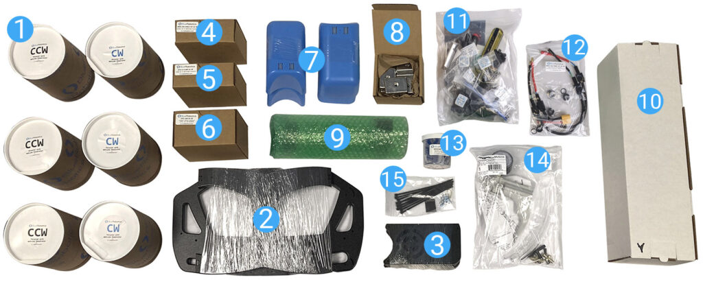
BlueROV2 kit contents
- T200 Thrusters, 3 x clockwise (CW) and 3 x counter-clockwise (CCW)
- Bottom and side panels and slot nuts
- Center panels and slot nuts
- Cradles for 4″ watertight enclosure
- Clamp for 3″ watertight enclosure
- Fathom-X Topside Interface (FXTI)
- Fairings with installed buoyancy foam (4)
- Box with ballast weights
- Battery Enclosure
- Box with Electronics Enclosure
- Bag with small components, tools, and screws
- Battery Power Cable Set with 5.5 bullet to XT90 adapter
- Container with desiccant bags
- Hand Operated Vacuum pump and bag with vacuum hoses and fittings
- Bag with extra leak sensor sponges, leak sensor tester, SD card adapter, zipties, and sticker
2. Open the bag of small components. Inside you will find:
- Bar30 Depth/Pressure Sensor
- 2 x Pressure Relief Valve (PRV)
- 2 x Bag of blank penetrators
- Bulkhead Wrench
- 2.5 mm hex driver
- Hex Key Set (1.5 mm, 2.0 mm, 3.0 mm)
- #2 Phillips head screwdriver
- 2 x Silicone grease – 6g pillow pack
- O-ring pick
- Multiple zip ties
- Frame assembly screws
- Electronics Enclosure cradle screws
- Electronics Enclosure mounting screws
- Thruster mounting screws
- Blue fairing mounting screws
- Ballast mounting screws
3. The Heavy Configuration Retrofit Kit should include the following components:
- 2 x T200 Thruster (CW and CCW)
- Heavy thruster guards
- Heavy fairings
- Heavy buoyancy foam
- 2 x Basic ESC
- 3 x Ballast weights
- Bag with screws, zip ties, and other small components
Installing Accessories
If you are building your BlueROV2 along with accessories such as the Newton Gripper or Ping sonars, open the accessory’s installation guide so you can follow along as you build your BlueROV2. The installation guide for any accessory can be found on its product page in the “Guides” section.
If you purchased a Fathom Spool for your tether, install the tether on the spool before connecting the tether to the ROV.
Assembling the Frame
Preparing the Frame Panels
To prepare the frame panels you will need the following parts:
- Bottom panel and slot nuts
- Center panels and slot nuts
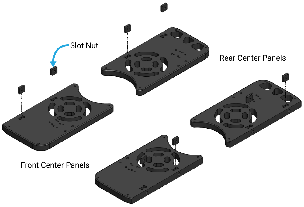
1. Insert the four slot nuts included with the bottom panel into the slot nut pockets.
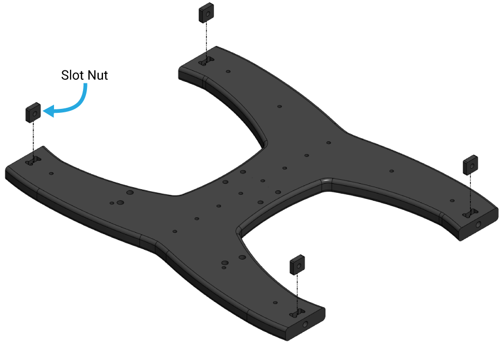
2. Insert the slot nuts included with the center panels into each nut pocket in the front and rear center panels. The rear center panels are the two panels with three large holes at one end. Each panel receives two slot nuts.
Mounting the Battery Enclosure to the Bottom Panel
To mount the battery enclosure to the bottom panel you will need the following parts and tools:
- 1 x Bottom panel
- 1 x Battery Enclosure
- 1 x Box labeled “Clamp for 3″ Watertight Enclosure”
- 1 x Threadlocker
- 1 x 3 mm hex key
- 1 x 2.5 mm hex driver
1. Inside the box labeled “Clamp for 3″ Watertight Enclosure” you will find the Enclosure Clamp (3″ Series), a bag with four M4x14 and four M3x12 screws, and two sets of adhesive rubber strips. Use the thinner pair of rubber strips if your ROV has acrylic tubes. Use the thicker pair of strips if your ROV has aluminum tubes. Remove the film from the adhesive and install the appropriate pair of strips onto the clamps.
2. Apply one drop of threadlocker to the bottom of each M4x14 socket head cap screw. The M4x14 screws are the larger, thicker screws. Roll the screws around on a paper towel to evenly spread the threadlocker and to remove excess threadlocker.
3. Attach one side of the Enclosure Clamp to the bottom panel using the four M4x14 socket head cap screws and the 3 mm hex key. Be sure that the screw head is sitting in the counterbore. The bottom panel is only counterbored on one side. Tighten the screws until you can feel them start to dig into the bottom panel.
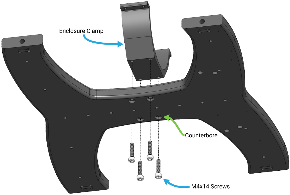
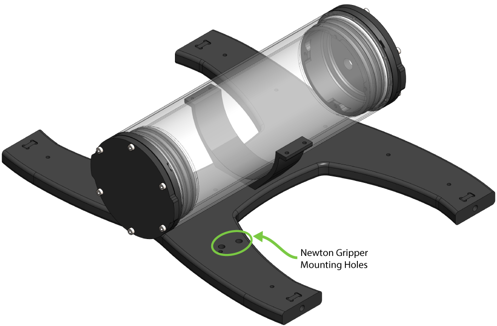
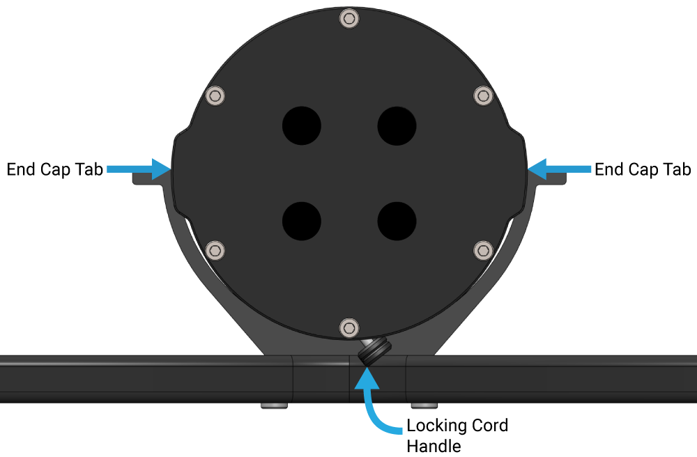
4. The bottom panel has Newton Gripper mounting holes on one side, place the Battery Enclosure on top of the Enclosure Clamp so the blank end cap is on the same side as the gripper mounting holes.
The other side of the Battery Enclosure with four penetrator holes should stick out far enough from the bottom panel to allow access to the locking cord handle. Orient the tube so the end cap tabs are in the horizontal position and the locking cord handle is in the bottom position. See diagram below.
5. Apply one drop of threadlocker to each of the four M3x12 screws. Roll the screws around on a paper towel to evenly spread the threadlocker and to remove excess threadlocker.
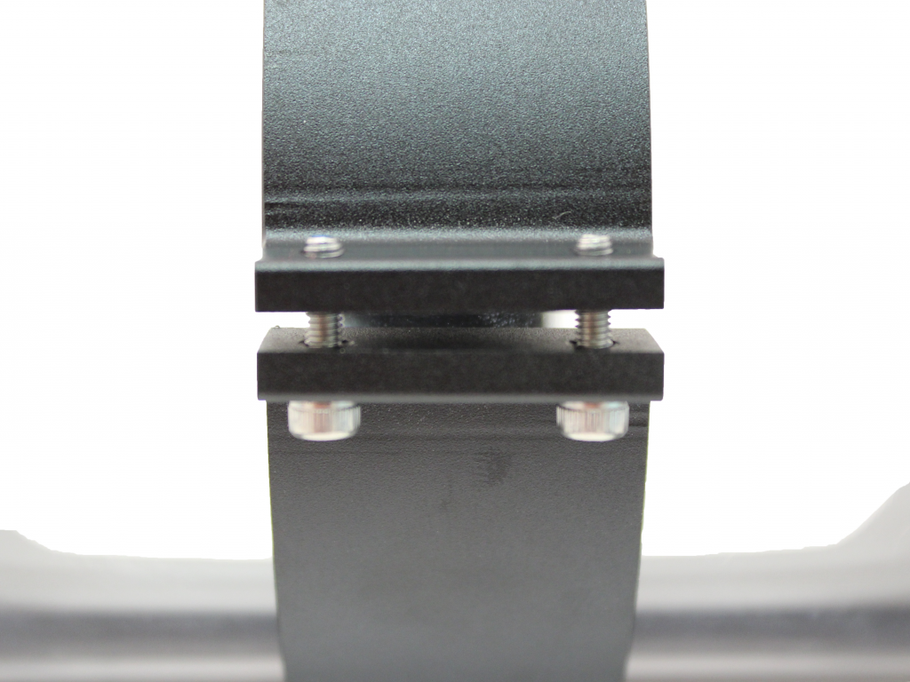
6. Place the other side of the 3” series Enclosure Clamp on top of the Battery Enclosure. The Enclosure Clamps (3″ Series) have threaded holes on one side and unthreaded through holes on the other. Place the clamps so the threaded holes on one clamp match up with the through holes of the other.
7. Using the 2.5 mm hex driver, install the four M3x12 screws into the Enclosure Clamps so that the screws pass through the unthreaded holes on the first clamp and are secured into the threaded holes on the alternate clamp. This means that one side will have screws that come in from the top clamp and the other side will have the screws come in from the underside (refer to picture below). Install all four screws loosely at first and then slowly tighten them on both sides evenly. Take care not to over tighten the screws.
8. When you are finished tightening the screws, both sides should look similar to this.
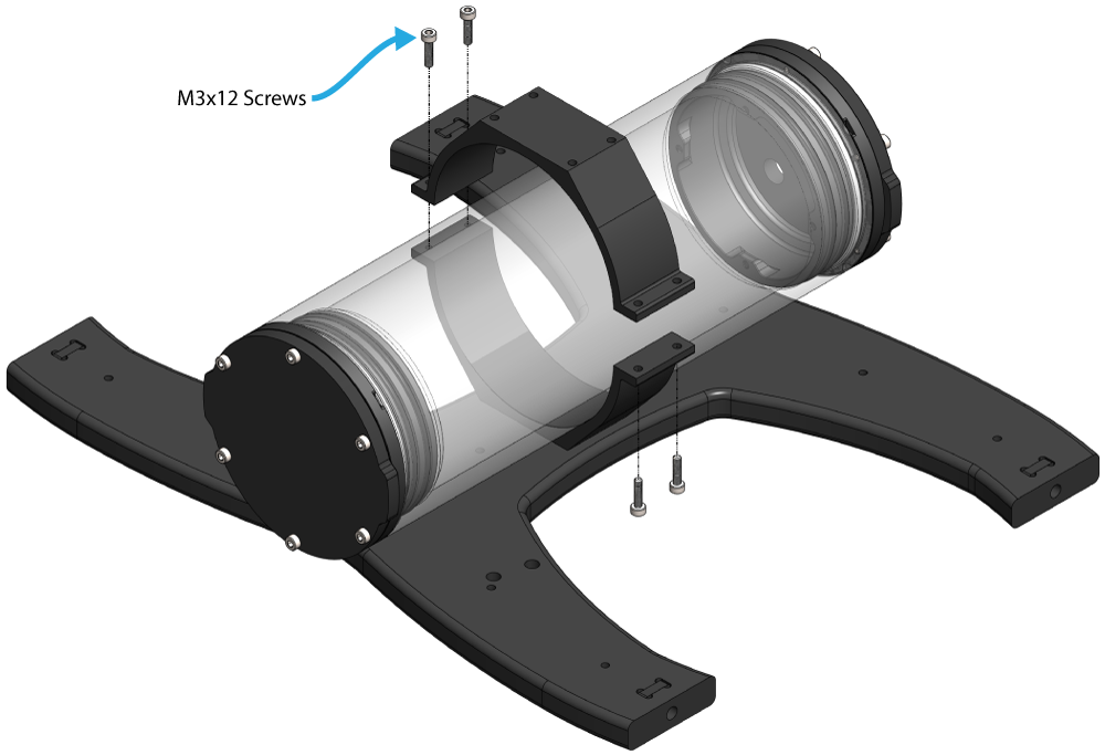
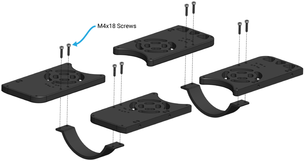
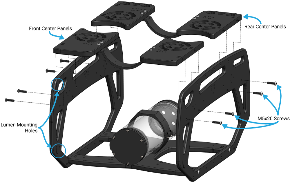
Assembling the Center Panels
To assemble the center panels you will need the following parts and tools:
- 1 x Box labeled “Cradles for 4″ Watertight Enclosure”
- 2 x Front center panels
- 2 x Rear center panels
- 1 x Threadlocker
- 1 x Bag labeled “Electronics Enclosure Cradle Screws [8] M4x18”
- 1 x 3 mm hex key
1. Apply one drop of threadlocker to each of the eight M4x18 Electronics Enclosure cradle screws. Roll the screws around on a paper towel to evenly spread the threadlocker and to remove excess threadlocker.
2. Attach the 4” Watertight Enclosure cradles to the front and rear center panels using the 3 mm hex key and the M4x18 screws. Tighten the screws until they indent the center panels slightly.
Assembling the Frame
To assemble the frame you will need the following parts and tools:
- 2 x Side panels
- 1 x Bottom panel with the Battery Enclosure installed
- 1 x Front center panel assembly
- 1 x Rear center panel assembly
- 1 x Bag labeled “Frame Assembly Screws [12] M5x20”
- 1 x 3 mm hex key
- 1 x Threadlocker
1. Apply one drop of threadlocker to each of the 12 M5x20 frame assembly screws. Roll the screws around on a paper towel to evenly spread the threadlocker and to remove excess threadlocker.
2. Install both side panels to the bottom panel using four of the M5x20 screws and the 3 mm hex key. The side of the Battery Enclosure with the blank end cap should be on the same side as the Lumen mounting holes. Tighten the screws until they indent the side panels slightly.
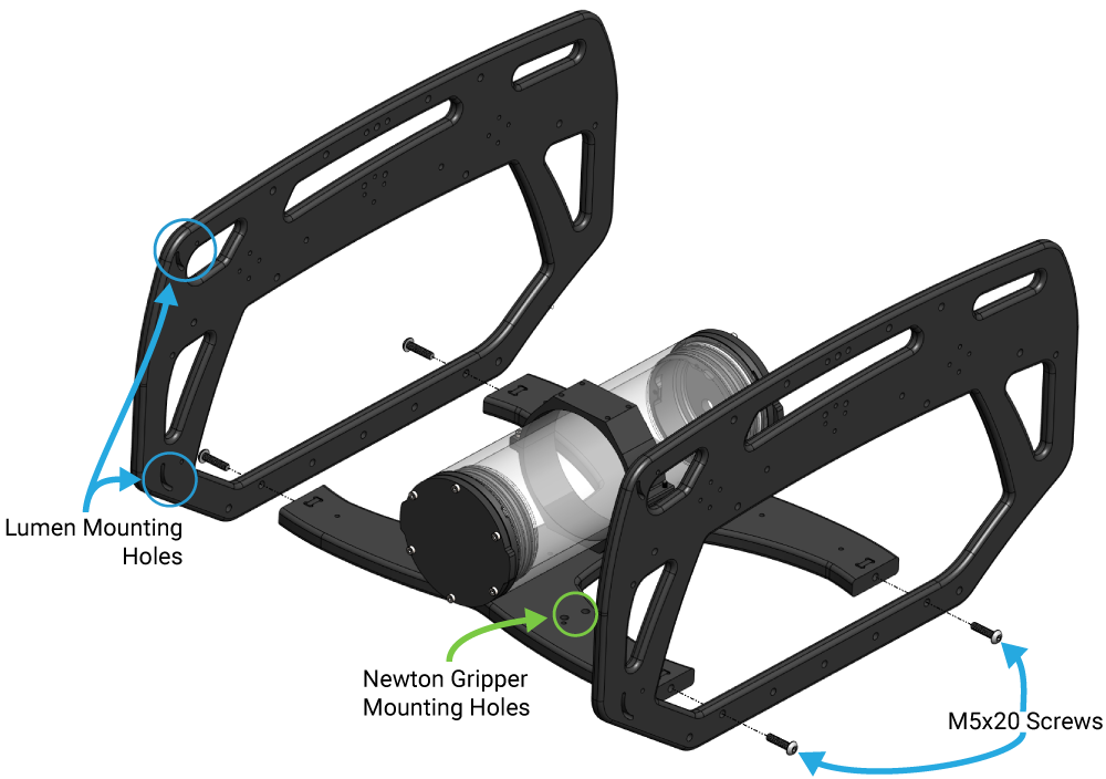
3. Install the center panel assemblies to the side panels using the remaining eight M5x20 screws and the 3 mm hex key. Keep in mind the panels with the three cutouts are the rear panels. Tighten the screws until they indent the side panels slightly.
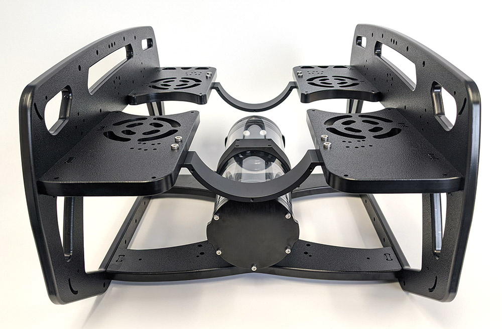
Now the BlueROV2 should look like the picture below.
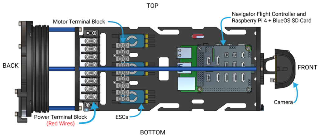
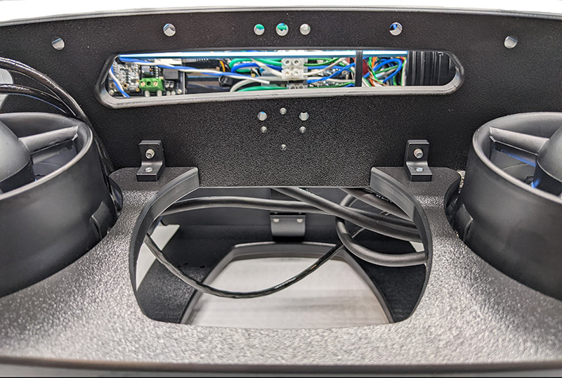
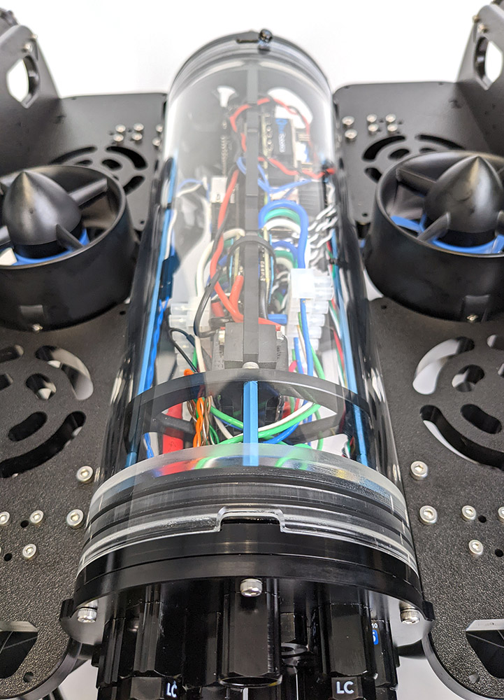
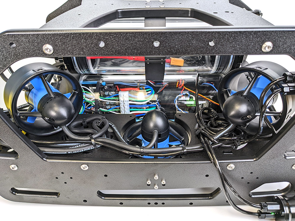
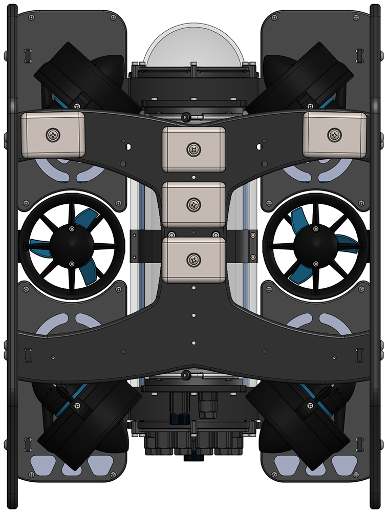
Electronics Enclosure Overview
The images below show the orientation of the main pieces of hardware in the Electronics Enclosure. They also point out the names of several of the important parts for assembly that will be discussed in the remaining instructions.
Top View
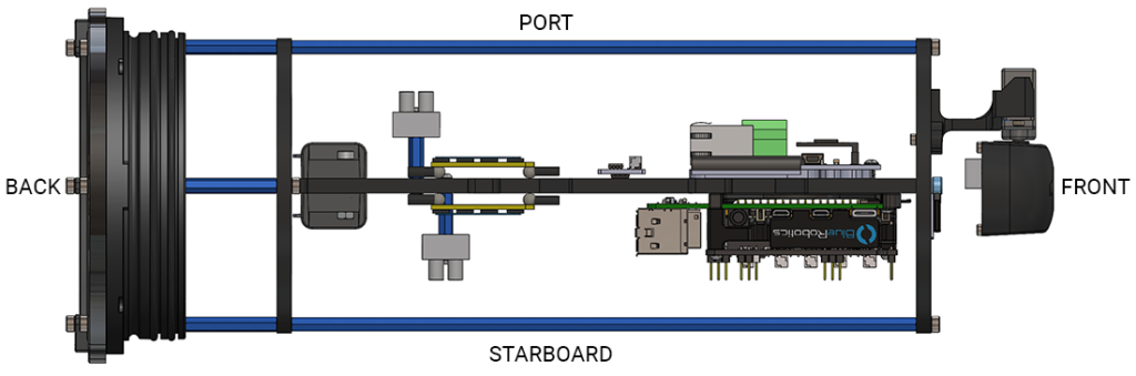
Top View
Starboard View
Starboard View
Port View
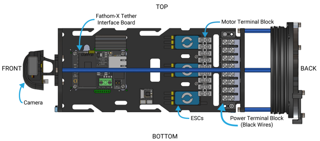
Port View
Front View
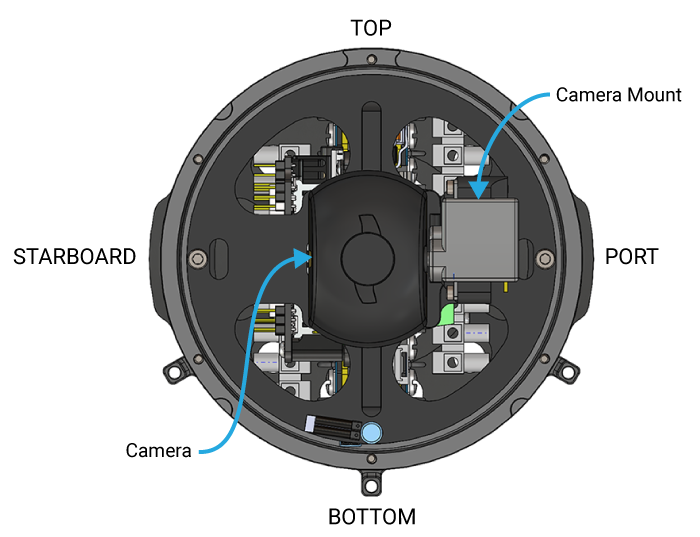
Front View
Installing the Cables
Removing the Electronics Enclosure End Cap
The end cap will need to be removed from the Electronics Enclosure in order to install the cable penetrators. To remove the end cap you will need the following parts and tools:
- 1 x Electronics Enclosure
- 1 x 2.5 mm hex driver
- 1 x Large flat head screwdriver (optional)
1. Pull out the locking cord from the rear Electronics Enclosure O-ring flange and set it to the side. The rear O-ring flange is the flange with the 18-hole end cap installed.
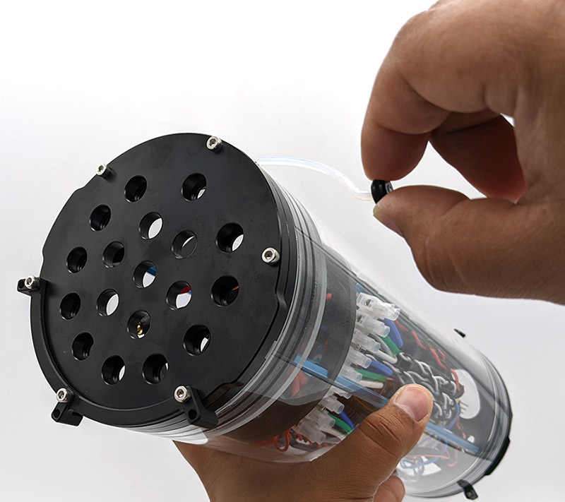
2. With the locking cord removed, separate the Electronics Enclosure tube from the rest of the Electronics Enclosure assembly. If this step is difficult, try pushing the flange up from the end cap tabs. Alternate pushing up from the tab on each side of the end cap until the flange is off. If this is still difficult, you can place a large flat head screwdriver into the slots on the O-ring flange and then twist to make a gap between the tube and the O-ring flange. Once you have the gap, you can wedge a screwdriver between the end of the tube and the O-ring flange to finish removing the tube.
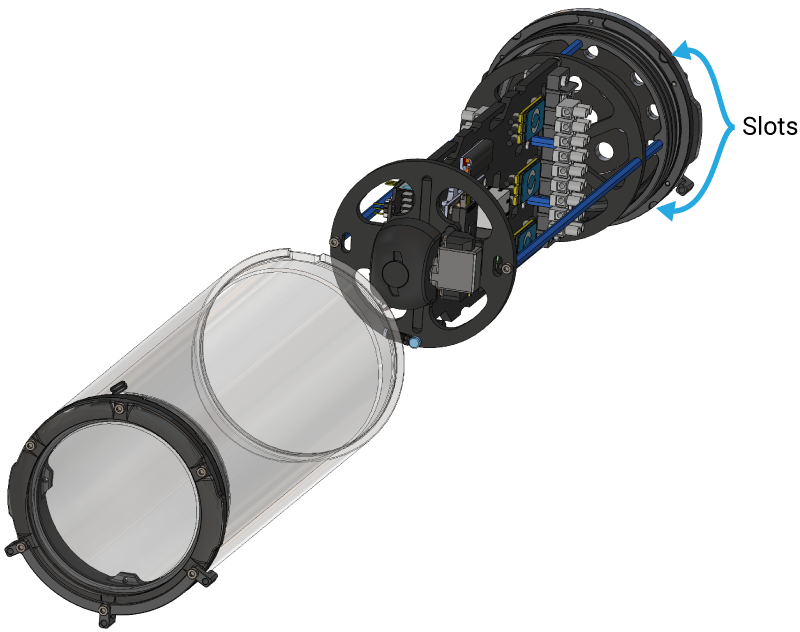
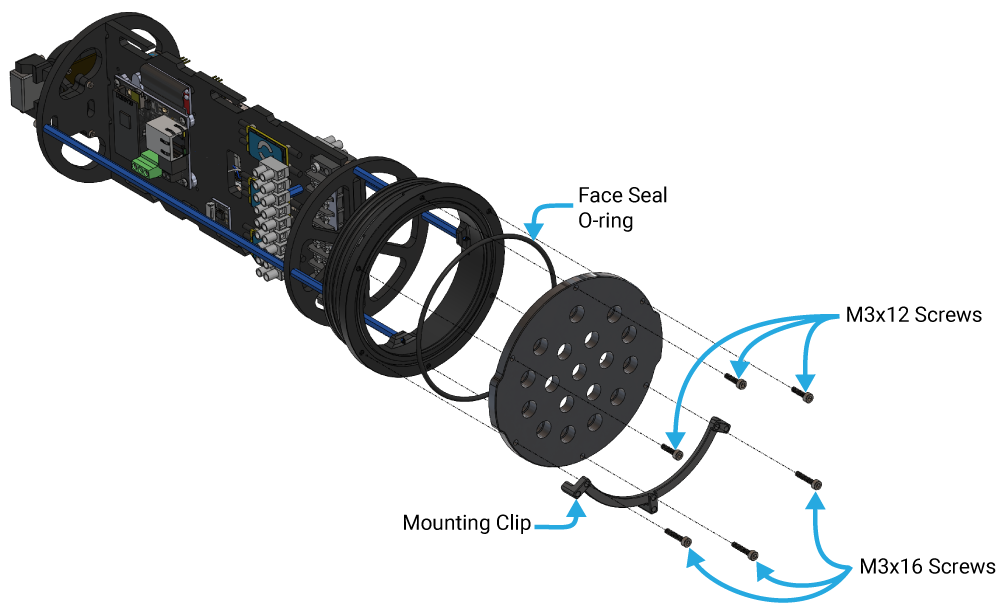
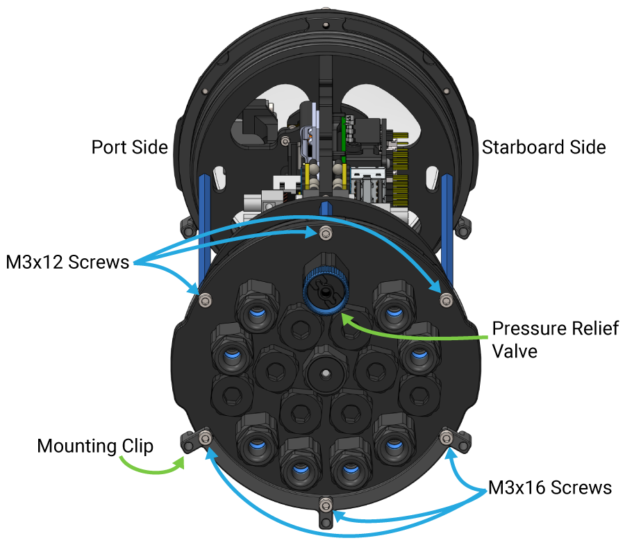
3. Remove the 18-hole end cap from the O-ring flange by removing the three M3x12 and three M3x16 screws using the 2.5 mm hex driver. Place the screws and mounting clip in a safe place. There is a face seal O-ring that sits in a groove between the end cap and flange, ensure this O-ring stays seated in this groove or place it somewhere it will not get dirty or damaged.
Installing the Penetrators
To install the Penetrators you will need the following parts and tools:
- 1 x 18-hole end cap
- 1 x Pressure Relief Valve with O-ring
- 1 x Bar30 Pressure Sensor with O-ring and penetrator nut
- 1 x Bag labeled “Power Cable Set for BlueROV2”
- 1 x Fathom ROV Tether with O-ring and penetrator nut
- 6 x T200 Thruster (3 x labeled “CW” and 3 x labeled “CCW”)
- 1 x Set of Lumen lights (if purchased) with penetrator nut and O-ring or, if not installing Lumen lights, collect one blank penetrator, penetrator nut, and O-ring from bag labeled “Blank Penetrator [4]”
- 6 x Blank penetrators, 6 x O-rings, and 4 x penetrator nuts, from bags labeled “Blank Penetrator [4]” (if you are installing accessories with a penetrator, use that penetrator instead of a blank)
- 1 x Silicone grease – 6g pillow pack
- 1 x Bulkhead Wrench
- 1 x 18-hole end cap
- 1 x Pressure Relief Valve with O-ring
- 1 x Bar30 Pressure Sensor with O-ring and penetrator nut
- 1 x Bag labeled “Power Cable Set for BlueROV2”
- 1 x Fathom ROV Tether with O-ring and penetrator nut
- 8 x T200 Thrusters, 4 x labeled “CW” and 4 x labeled “CCW” (6 x from the standard kit and 2 x from the Heavy kit)
- 1 x Set of Lumen lights (if purchased) with penetrator nut and O-ring or, if not installing Lumen lights, collect one blank penetrator, penetrator nut, and O-ring from bag labeled “Blank Penetrator [4]”
- 4 x Blank penetrators, 4 x O-rings, and 4 x penetrator nuts, from bags labeled “Blank Penetrator [4]” (if you are installing accessories with a penetrator, use that penetrator instead of a blank)
- 1 x Silicone grease – 6g pillow pack
- 1 x Bulkhead Wrench
1. Labeling the thrusters now will make installing them easier later. You can use masking tape and a marker to label the thrusters as follows:
- Take the three thrusters from containers labeled “CCW” and label them “1”,”2″, and “5”.
- Take the three thrusters from containers labeled “CW” and label them “3”,”4″, and “6”.
- Take the four thrusters from containers labeled “CCW” and label them “1”,”2″,”5″, and “8”.
- Take the four thrusters from containers labeled “CW” and label them “3”,”4″,”6″, and “7”.
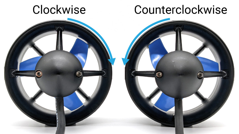
If you choose not to label the thrusters, ensure you keep track of the propeller direction (clockwise or counter-clockwise) for each thruster as you unpack them.
If you lose track of which thrusters are clockwise or counter-clockwise, look at the thrusters from the front nose cone and compare to the picture below to determine the propeller direction.
2. Each thruster container includes a small bag with one O-ring and one penetrator nut. Collect the O-ring from each thruster container. The penetrator nuts will not be used when installing on the 18-hole end cap.
3. Get both power cables and two O-rings from the bag labeled “Power Cable Set for BlueROV2”. The battery power cable with red heat shrink wrapping is “POWER+” and the cable with black heat shrink wrapping is “POWER–”.
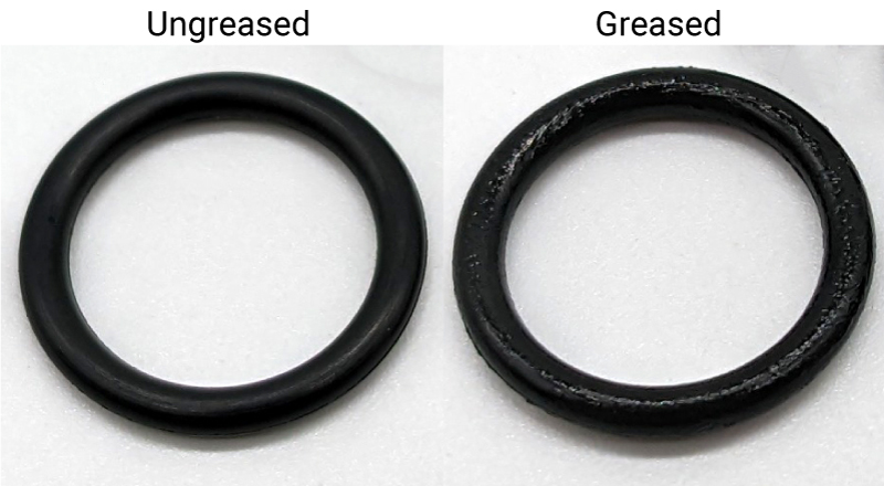
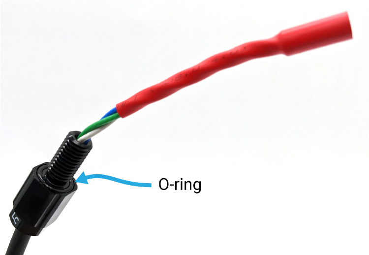
4. Collect all of the thruster O-rings and the O-rings from the Pressure Relief valve, Bar30 Pressure Sensor, power cables, tether, Lumen lights, and blank penetrators and coat them with a thin, even layer of silicone grease. Do not apply too much grease. The following picture shows an O-ring with the appropriate amount of grease compared to one with no grease.
5. Install the O-rings onto all of the penetrators. The O-rings should sit in the groove on the underside of the penetrator. For the power cables, install the O-rings on the side with the female 5.5 mm bullet connector.
6. Wipe the exterior surface of the Electronics Enclosure end cap clean with isopropyl alcohol or isopropyl alcohol wipes, and make sure it is free of any particles in the areas where the penetrator O-rings will sit.
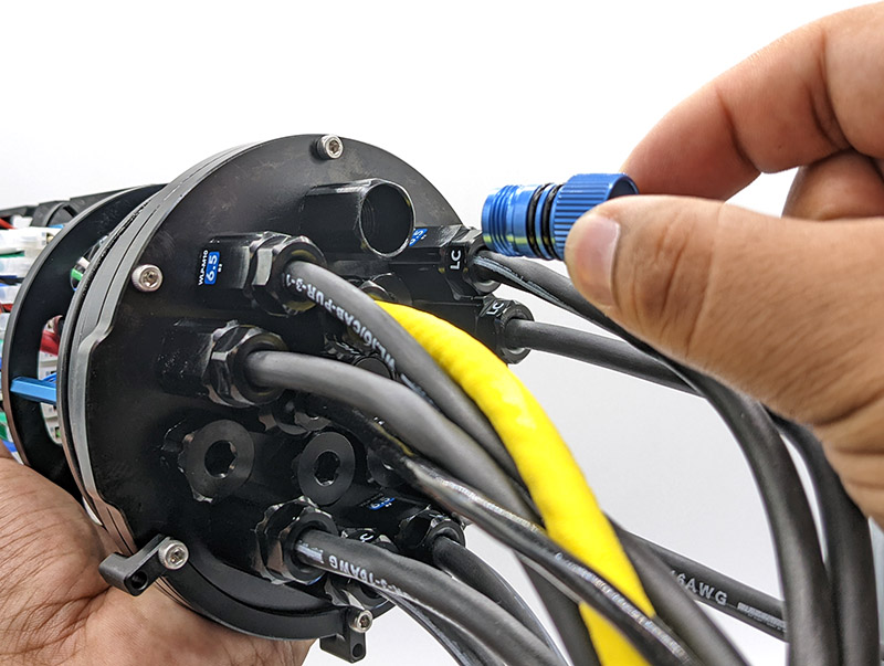
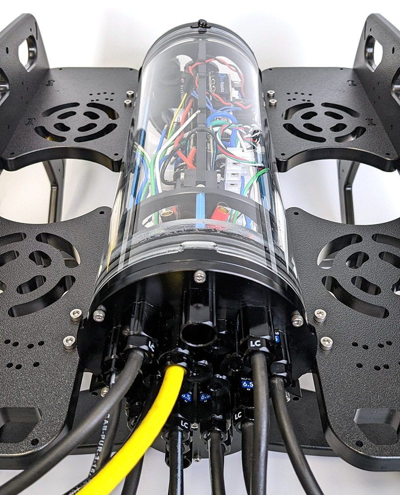
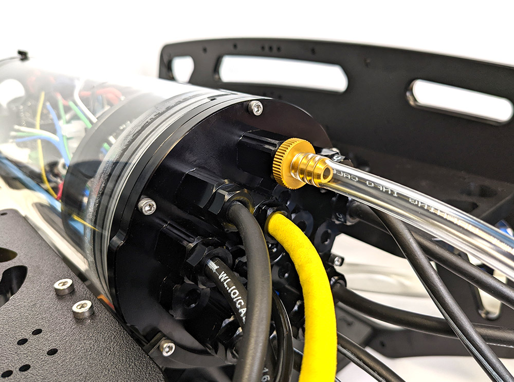
7. The 18-hole end cap has one penetrator hole that is spaced farther from the rest. The end cap should be oriented so this hole is at the “top”. The diagram below shows where the penetrator for each component should be installed on the end cap. It also shows the order in which they should be installed for easiest installation. Always double check that an O-ring is installed in each penetrator as you install them. If you are installing accessories such as the Newton Gripper or Ping sonar, install its penetrator in one of the “BLANK” penetrator locations. If you are using a torque wrench to install the penetrators, tighten to 3.5 N⋅m.


The holes shown in green in the diagram are unthreaded holes. to install a penetrator in an unthreaded hole, insert the penetrator through the hole and fasten a penetrator nut on the other side. Tighten the nut and penetrator by hand until finger-tight. Use the Bulkhead Wrench to fully tighten the penetrator until it no longer rotates in the hole. The penetrator is installed properly when you are not able to loosen it using your fingers.
The holes shown in blue in the diagram are threaded holes. To install a penetrator in a threaded hole, screw the penetrator clockwise into the hole by hand until finger-tight, do not install a penetrator nut on the back of the penetrator. Use the M10 Bulkhead Wrench to finish tightening the penetrator completely. If the penetrator cannot be loosened using your fingers, it is tight enough.
At the end of this step there should be no empty penetrator holes in the 18-hole end cap.
Installing the End Cap
To reinstall the 18-hole end cap to the Electronics Enclosure rear flange you will need the following parts and tools:
- The face seal O-ring, 3 x M3x12, 3 x M3x16 screws, and the mounting clip that were removed from the end cap earlier
- 1 x 18-hole end cap with all penetrators installed
- 1 x Electronics Enclosure assembly
- 1 x Silicone grease – 6g pillow pack
- 1 x 2.5 mm hex driver
1. Clean the face seal O-ring and make sure that it is free of any debris or damage.
2. Clean the rear Electronics Enclosure O-ring flange and make sure that the O-ring groove is free of any debris or damage.
3. Apply silicone grease to the O-ring.
4. Install the face seal O-ring into the O-ring flange groove.
5. Apply one drop of threadlocker to each of the M3 screws. Roll the screws around on a paper towel to evenly spread the threadlocker and to remove excess threadlocker.
6. Install the 18-hole end cap with all penetrators installed onto the O-ring flange. Install the screws in a crisscross sequence. Do not fully tighten any screws when first installing them, it may cause the O-ring to slip out of its groove. The end cap’s orientation when installed should match the image below. Use the longer M3x16 screws to secure the mounting clip in the correct orientation. The mounting clip should be installed flat against the end cap with the longer extensions pointing towards the rest of the Electronics Enclosure assembly.
Finishing the Battery Enclosure
To complete the assembly of the Battery Enclosure you need the following parts and tools:
- Electronics Enclosure assembly
- 4-Hole end cap and flange assembly from Battery Enclosure
- 1 x Pressure Relief Valve with O-ring and nut
- 1 x bag labeled “Power Cable Set for BlueROV2”
- 1 x Blank penetrator, O-ring, and nut from bag labeled “Blank Penetrator [4]”
- 1 x Silicone Grease – 6g pillow pack
- 1 x Bulkhead Wrench
1. Pull out the locking cord and separate the 4-hole end cap and flange assembly from the rest of the Battery Enclosure by pulling it off. If this is difficult, you can place a large flat head screwdriver into the slots on the O-ring flange and then twist to make a gap between the tube and the O-ring flange. Once you have a gap, you can wedge a screwdriver between the end of the tube and the O-ring flange to finish removing the tube.
2. Take two O-rings and two penetrator nuts from the bag labeled “Power Cable Set for BlueROV2”. Collect the O-rings from the Pressure Relief Valve and blank penetrator. Apply silicone grease to the O-rings.
3. Install an O-ring on both power cables, the Pressure Relief valve and the blank penetrator.
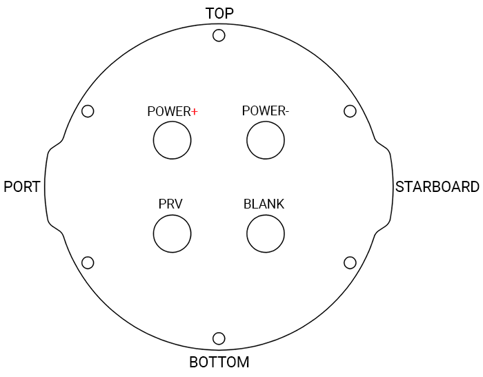
4. Install the penetrators on the Battery Enclosure end cap so they match the diagram below. Be aware of the location of the rotation locking tab at the edge of the flange as this needs to match up with the slot in the tube when reinstalled. Insert the penetrators through the holes and fasten a penetrator nut on the other side. Tighten the nut and penetrator by hand until finger-tight. Use the Bulkhead Wrench to fully tighten the penetrator until it no longer rotates in the hole. The penetrator is installed properly when you are not able to loosen it using your fingers. If using a torque wrench, tighten to 3.5 N⋅m.
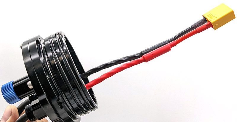
5. Get the XT90 to 5.5 mm bullet connector adapter from the power cable set bag and install it on the battery power cables. Match the heat shrink colors of the adapter to the heat shrink on the power wires.
6. Remove the PRV plug from the PRV Bulkhead from both the Battery Enclosure and Electronics Enclosure. Remove the plug by turning the plug counterclockwise until you can take it out.
7. Reinstall the end cap and flange assembly back onto the Battery Enclosure to proceed with the preliminary vacuum test.
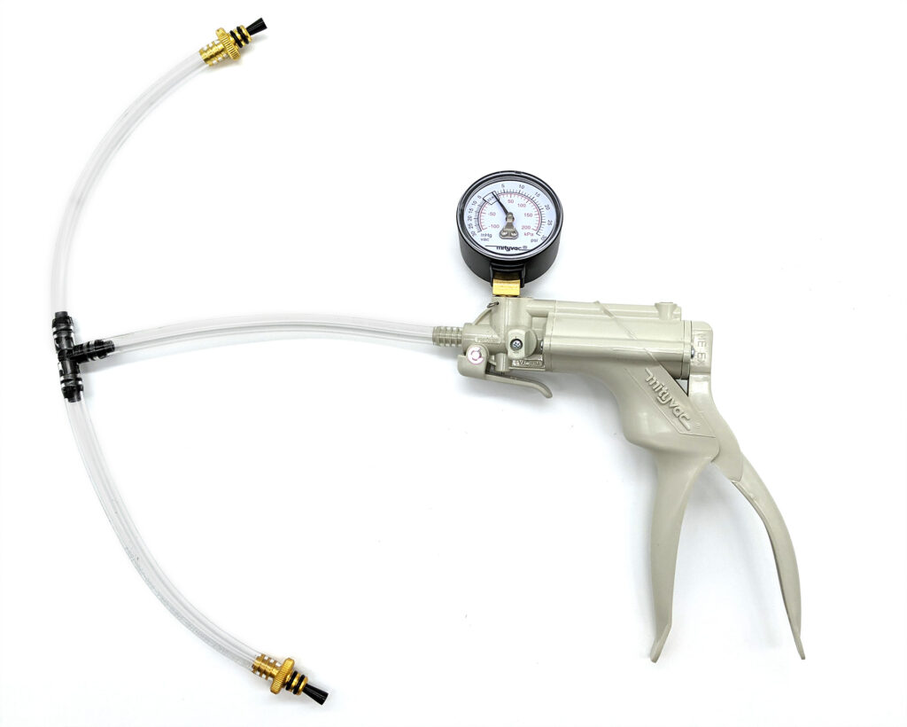
Preliminary Vacuum Test
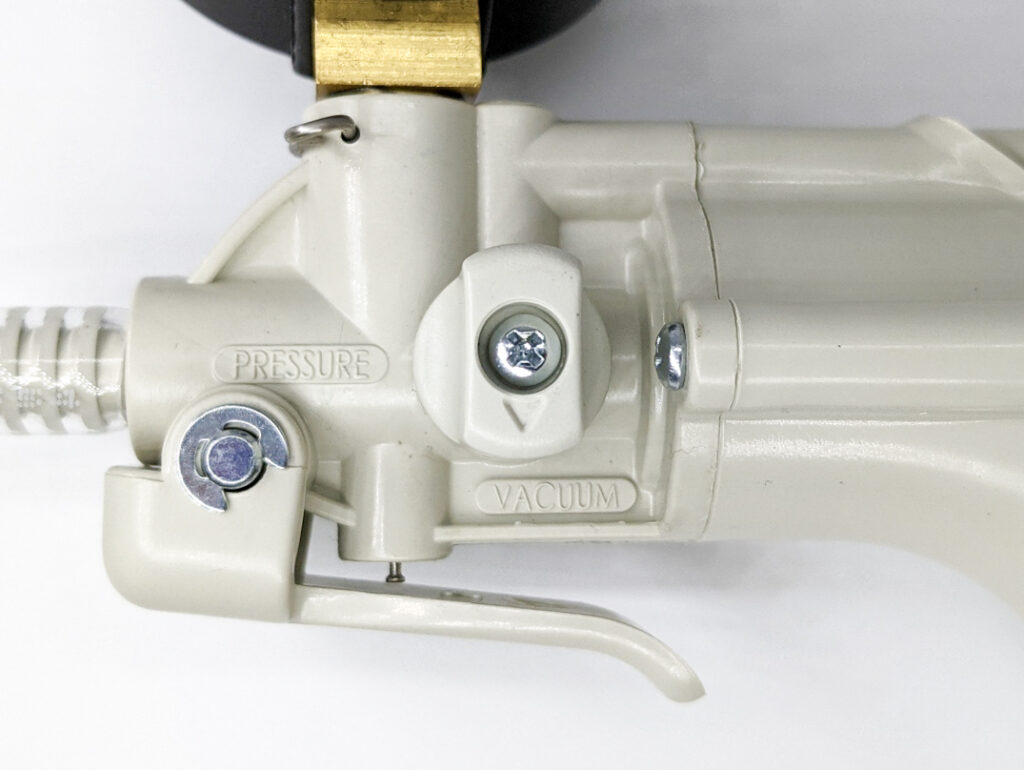
This is the best point in the assembly process to perform a vacuum test. Since you have installed all of the penetrators, but have not done any of the wiring, troubleshooting will be as easy as possible. To perform the vacuum test, you will need:
- 1 x Hand Operated Vacuum Pump
- 1 x Bag with vacuum hoses and fittings
- Electronics Enclosure
- Battery Enclosure
1. Install the Electronics Enclosure tube onto the Electronics Enclosure assembly. Tuck in all of the loose wires through the cutouts in the circular part of the electronics tray to prevent pinching any of the wires while installing the tube.
2. Assemble the vacuum tee from the provided hoses and fittings.
Now you are ready to perform the preliminary vacuum test.
Performing the Test
Watch the video tutorial or follow the written instructions below for performing the vacuum test.
1. Test your vacuum pump to ensure that it is not leaking. See our Testing the Test Setup Tutorial for detailed instructions.
2. Insert one of the vacuum plugs into the Battery Enclosure PRV bulkhead.
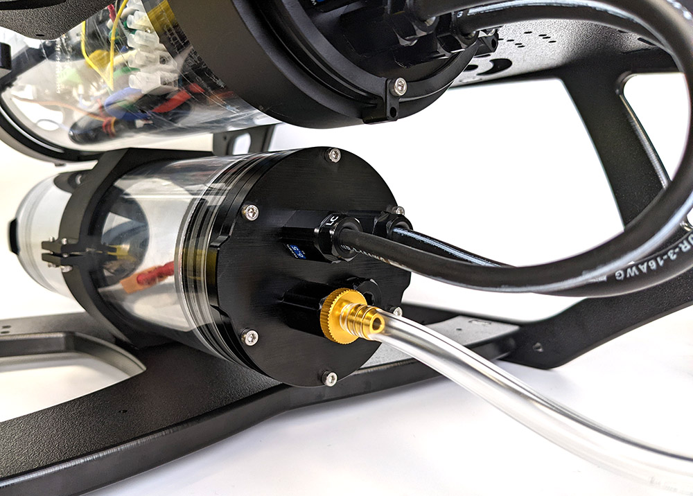
3. Insert the other vacuum plug into the Electronics Enclosure PRV bulkhead.
4. Turn the knob on the side of the vacuum pump so it is in the “VACUUM” setting.
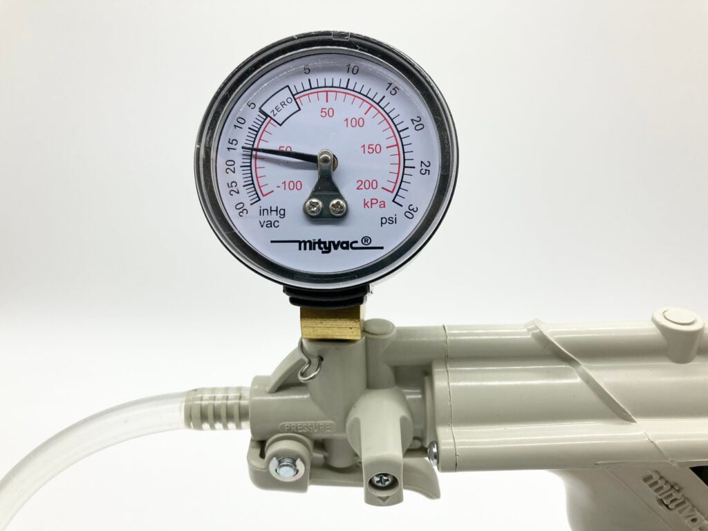
5. Pump the vacuum until the gauge reads 15 inHg [50 kPa] vacuum. If you cannot pull a vacuum, try the suggestions in the Vacuum Test Troubleshooting section below.
6. Let the BlueROV2 and pump sit for 10 minutes.
7. If the gauge reads 14 inHg [47 kPa] or above after 10 minutes, your seals are acceptable. If not, proceed to the troubleshooting section below.
To continue assembling the BlueROV2, insert the locking cord into the Battery Enclosure to lock the tube to the flange and insert the PRV plug to the PRV bulkhead and turn the plug clockwise until it stops to seal it. Remove the Electronics Enclosure tube from the rest of the Electronics Enclosure assembly.
Vacuum Test Troubleshooting
If the gauge reads below 14 inHg [47 kPa] vacuum after 10 minutes, you should check the following:
1. Make sure that the M3 screws on the front and back end caps of the battery and electronics enclosure are tightened using the M2.5 hex driver. If you are able to tighten one or more, perform the vacuum test again.
2. Make sure that the penetrators on the battery and electronics enclosure are fully tightened. Check by attempting to loosen by hand. If you are able to loosen one or more, tighten them then perform the vacuum test again.
3. Make sure that all penetrators have an O-ring installed. If any are missing, install then perform the vacuum test again.
4. Check that the face seal O-rings and radial O-rings are installed in the battery and electronics enclosures and are in good condition. If you find a damaged or missing O-ring, install and perform the vacuum test again.
5. Make sure you are testing both the Electronics Enclosure and the Battery Enclosure at the same time. If they were tested individually, assemble the vacuum tee and test both enclosures at the same time.
6. Do NOT add more silicone grease to the O-rings. The O-rings only need a thin coating of grease, adding more will not solve a leak in the enclosure.
If you are still having trouble holding vacuum, please contact us at [email protected]
Cable Connections
Installing the Power and Signal Wires from the Penetrators
To install the wires from the penetrators you will need the following parts and tools:
- Electronics Enclosure assembly
- 1 x #2 Phillips head screwdriver
- 1 x Small (~2 mm) flat head screwdriver
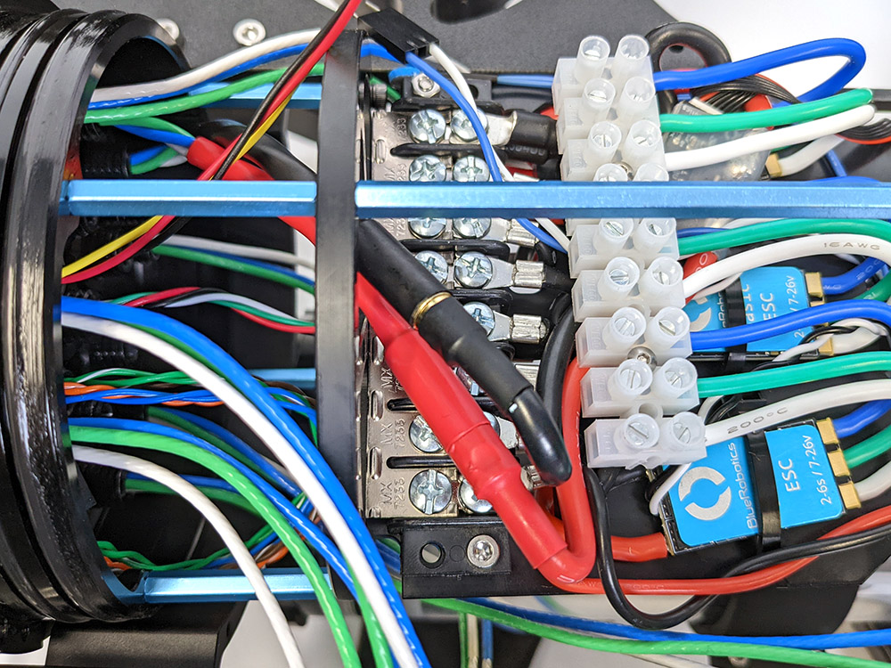
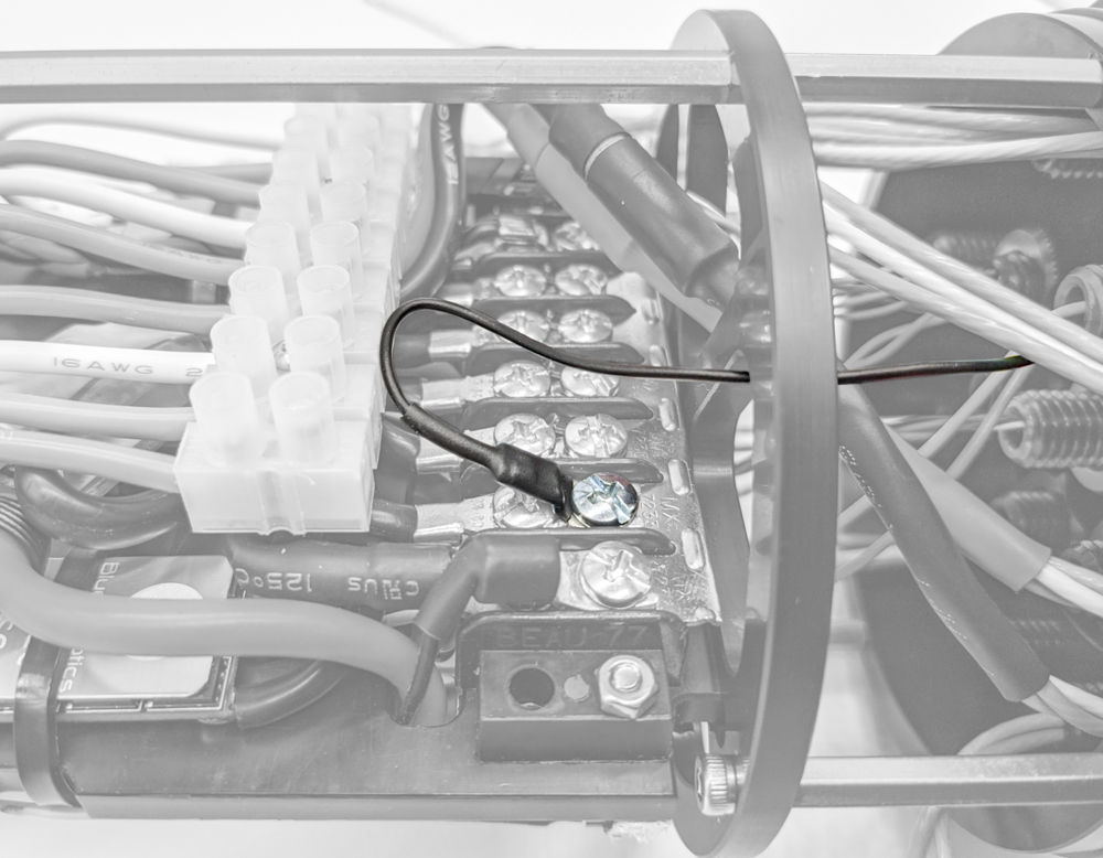
There is a power terminal block on either side of the electronics tray, one for all of the red power wires and one for all of the black (ground) power wires. When installing the power wires for your components, double-check they are connected to the correct power terminal block. Use the included #2 Phillips head screwdriver to loosen and tighten the screw terminals on the power terminal blocks.
1. Connect the 5.5 mm male bullet connectors from the Power Sense Module to the 5.5 mm female bullet connectors from the power cables. Match the heat shrink color red to red and black to black.
2. Connect the Lumen power wire (red) to an available screw terminal on the power terminal block with the other red wires.
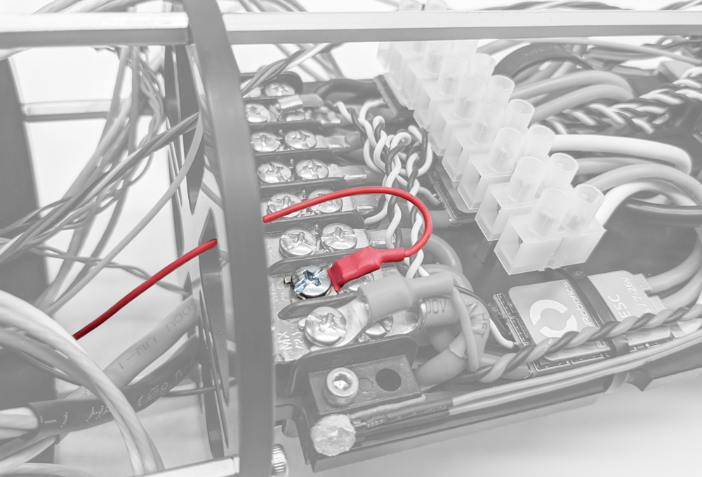
3. Connect the Lumen ground wire (black) to an available screw terminal on the power terminal block with the other black wires.
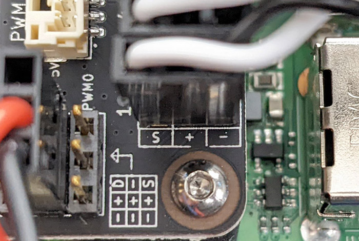
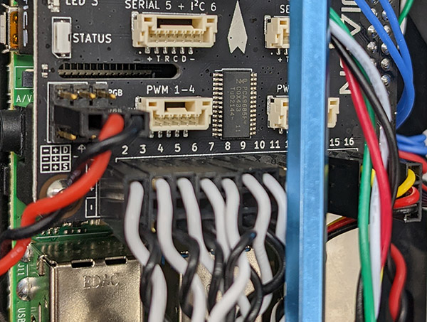
4. Connect the Lumen signal wire (yellow) to Navigator PWM output channel 13 with the yellow wire connected to the topmost pin.
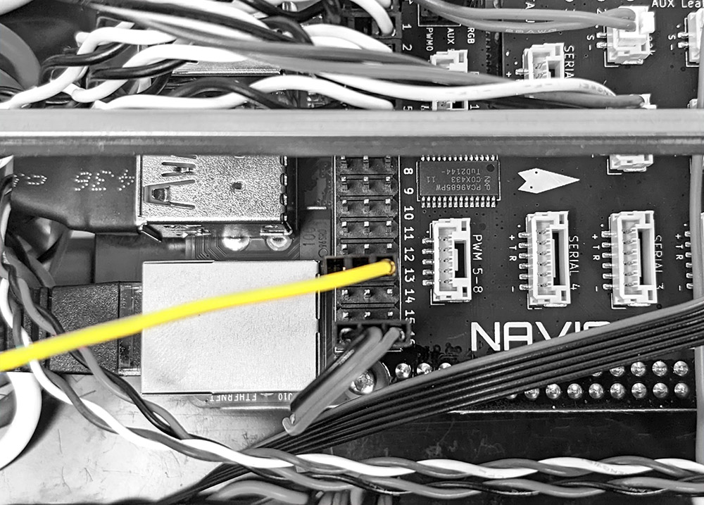
The Navigator output rail is also labeled to show the correct orientation of the connectors.
5. Connect the Bar30 cable to one of the I2C ports on the Navigator.
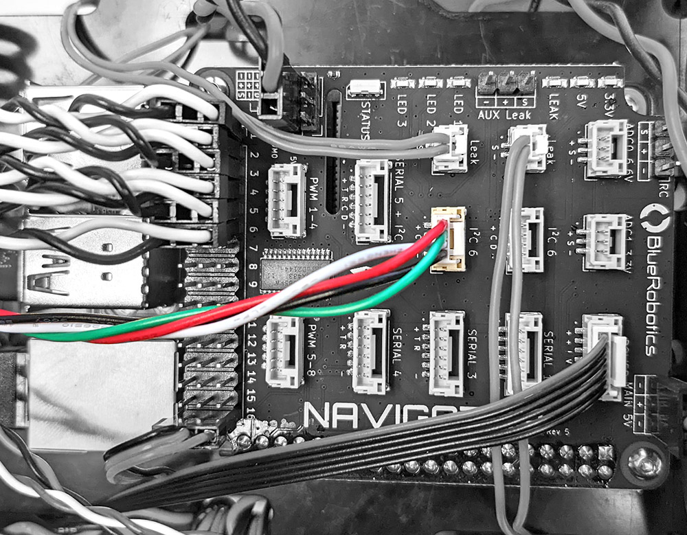
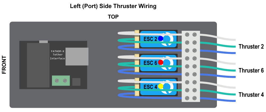
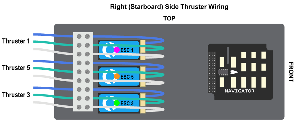
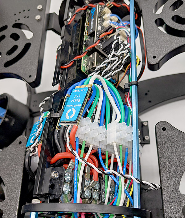
6. Connect the thruster motor wires to the motor wire terminal blocks, match the thruster number to the ESCs as shown in the diagrams below. The ESCs are color coded with paint in the corner to help identify them. Use a small (~2 mm) flat head screwdriver to loosen and tighten the connectors on the motor terminal blocks.
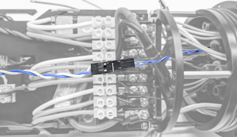
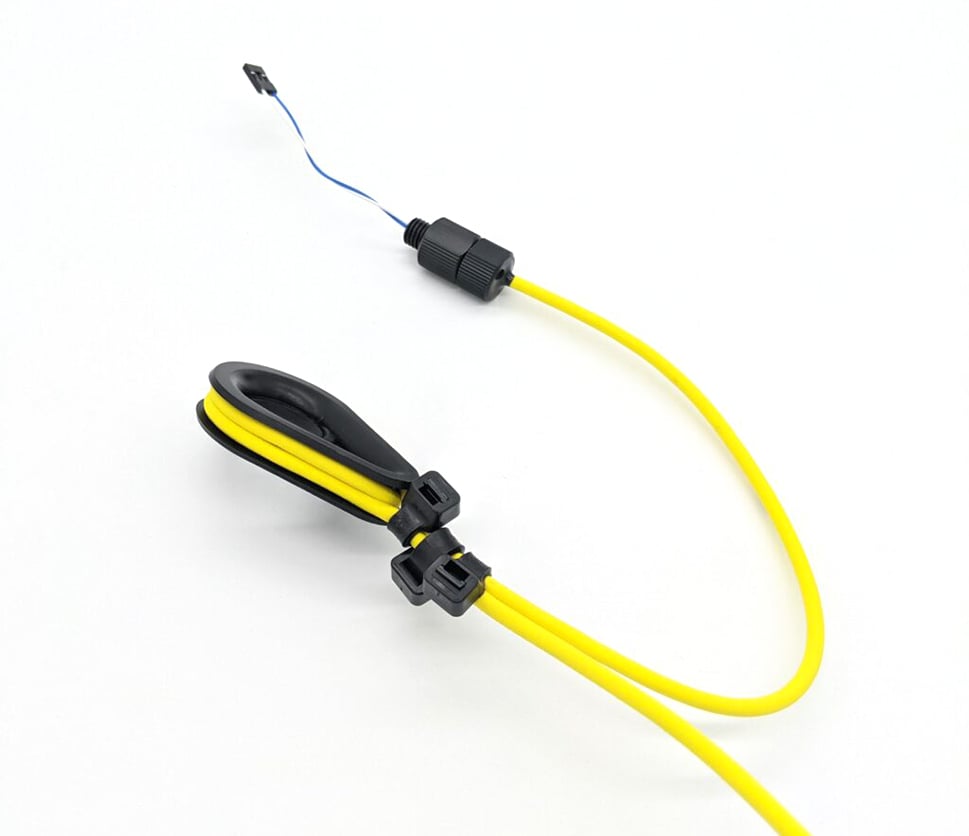
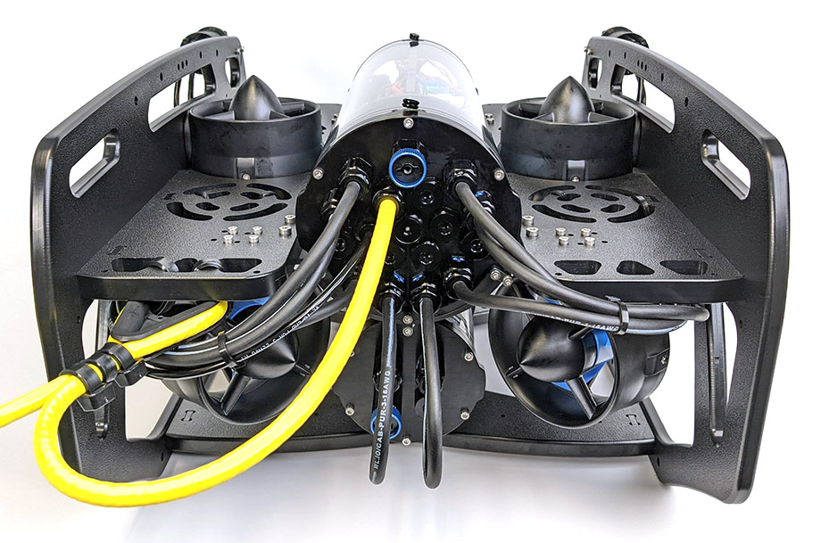
7. Connect the female tether wire connector with blue and white wires to the extension cable that is connected to the Fathom-X Tether Interface Board. The three other pairs of wires from the tether are not used for operating the BlueROV2 but can be utilized for future expansion.
8. Connect the power and signal/data wires from any accessories. Refer to the accessory’s installation instructions.
Installing Additional ESCs and Motor Wires
To install the additional ESCs from the heavy kit you will need the following parts and tools:
- 2 x Basic ESC (from Heavy Retrofit Kit)
- 2 x 3 Pole Euro Terminal Block (from Heavy Retrofit Kit)
- 1 x #2 Phillips head screwdriver
- 1 x Small (~2 mm) flat head screwdriver
1. Connect the ESC power wires onto available screw terminals on the power terminal blocks. Use the cutouts in the electronics tray to route ESC power cables to the correct power terminal block as necessary. An ESC should be installed on each side of the electronics tray.
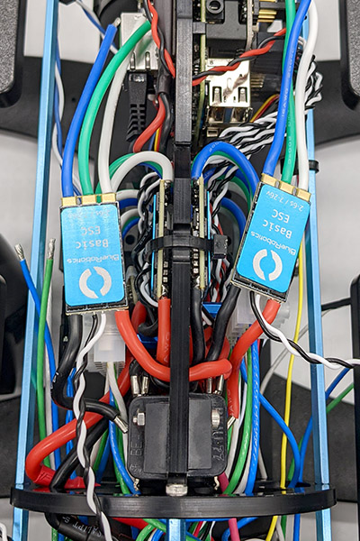
2. Connect the motor power wires from thrusters 7 and 8 to the ESCs using the 3 pole Euro terminal blocks and your 2 mm flat head screwdriver. Slide the 3-pole Euro terminal blocks under the aluminum standoffs so they sit between the standoff and the 9-pole Euro terminal blocks as shown below.
3. Plug the ESC signal wire from the ESC connected to thruster 7 into channel 7 on the Navigator with the white signal wire connected to the topmost pin. Plug the ESC signal wire from the ESC connected to thruster 8 into channel 8 on the Navigator with the white signal wire connected to the topmost pin. Use the cutouts in the electronics tray to route the wires as necessary.
4. Secure the ESCs to the other ESC motor power wires using a zip tie.
Cable Routing
Now is a good time to route and tidy up the cables in the Electronics Enclosure. This step is optional but will help prevent snagging the cables when installing the Electronics Enclosure tube. To do so, you will need the following:
- Small zip ties
- Wire cutters or scissors
1. On the starboard side (Navigator side) the Bar30 wires and the Lumen signal wire can be zip tied to the long hex standoff. Make sure that the locking head of the zip tie and the wires are oriented to the inside of the long hex standoff.
2. On the port side (Fathom-X Tether Interface Board side), the blue and white tether extension cable can be zip tied to the long hex standoff. Make sure that the locking heads of the zip ties and the wires are oriented to the inside of the long hex standoff.
3. Tuck any other stray cables out of the way so they do not get snagged or pinched when installing the Electronics Enclosure tube.
Final Assembly
The rest of the assembly process involves installing all of the components to the frame. To ensure this goes smoothly, lay the Electronics Enclosure with thrusters, tether, lights, and blank penetrators installed on top of the enclosure cradles but do not secure it with any screws yet. Straighten out all of the cables and work out any twists in the cables that may have developed during installation.
Mounting the Thrusters to the Frame
To mount the thrusters to the frame, you need the following parts and tools:
- Electronics Enclosure assembly with thruster, tether, lights, and blank penetrators installed
- Assembled ROV frame
- 1 x Bag labeled “Thruster Mounting Screws [8] M3x12 [16] M3x16”
- 1 x 2.5 mm hex driver
- Electronics Enclosure assembly with thruster, tether, lights, and blank penetrators installed
- Assembled ROV frame
- 1 x Bag labeled “Thruster Mounting Screws [8] M3x12 [16] M3x16”
- 1 x Bag labeled “Thruster Mounting Screws [8] M3x12” (from Heavy Retrofit Kit)
- 1 x 2.5 mm hex driver
The horizontal thrusters have two mounting options. One is at a 45° angle to forward, and the other is at a 30° angle to forward. The thrusters mounted at 45° will give you equal thrust in all directions and is the default mounting position. Mounting the thrusters at 30° will give you 25% more forward thrust in exchange for 25% less thrust in sideways direction.
Default 45° Mounting
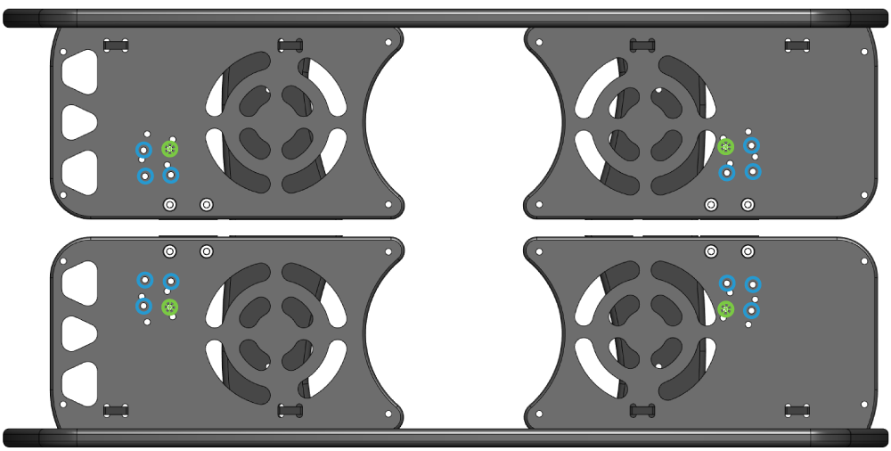
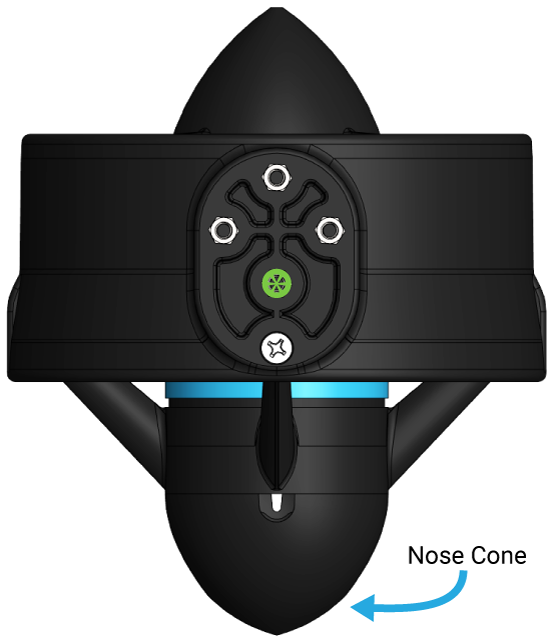
To mount the thrusters at 45° use the holes shown in the picture below. The hole with the green asterisk (*) is the hole that should be closest to the nose cone on the thruster.
30° Mounting Option
To mount the thrusters at 30° use the holes shown in the picture below. The hole with the green asterisk (*) is the hole that should be closest to the nose cone on the thruster.
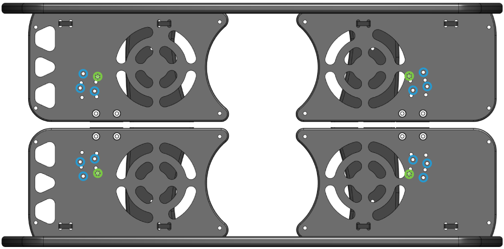
For the sake of clarity, the hole with the green asterisk (*) on the thruster shown below is the hole that is closest to the nose cone.
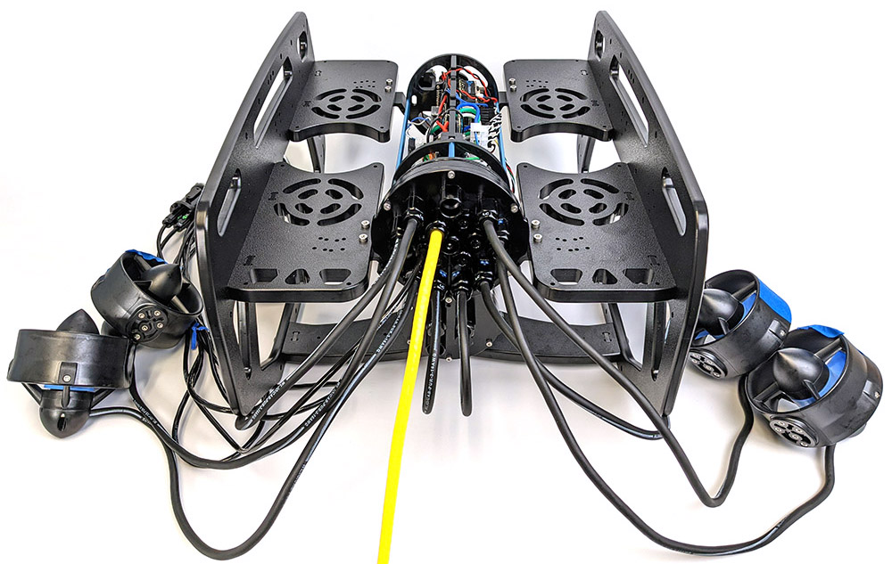
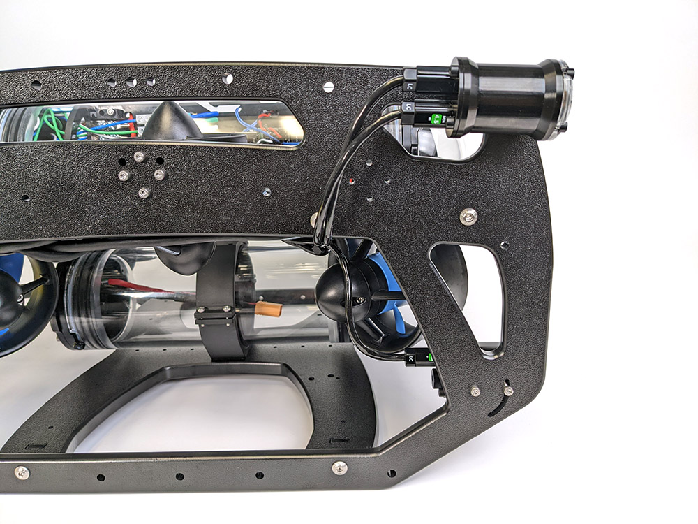
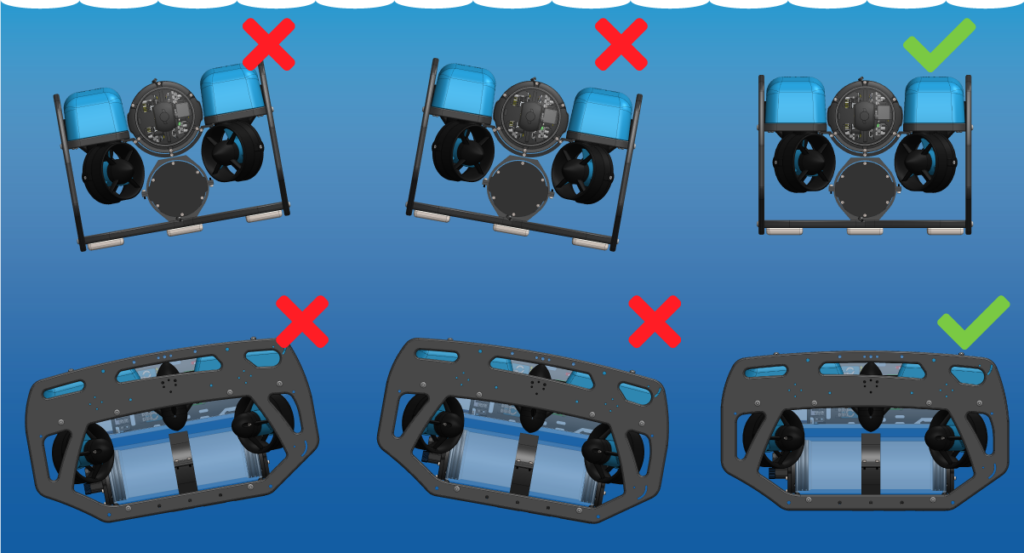
The diagram below shows where the thrusters go and how they should be oriented. The green thrusters should have counter-clockwise (CCW) propellers and blue thrusters should have clockwise propellers (CW). Be sure to install the front thrusters before the rear thrusters. The front thrusters cannot be installed if the rear thrusters are installed first. Route all thruster cables underneath the center panels. The area above the center panels should be kept clear to install the fairing later in this guide.
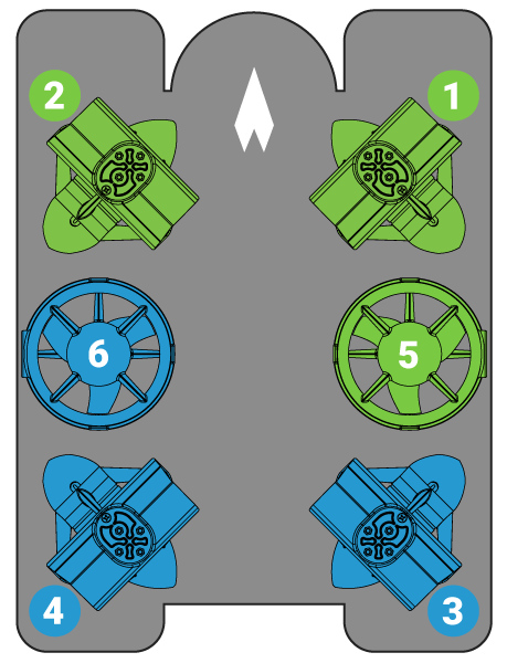
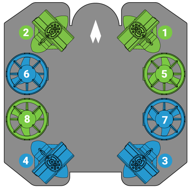
1. Install thrusters 1 and 2 underneath the front center panels using the longer M3x16 screws. Tighten the screws so that they indent the frame slightly. It is physically possible to keep turning the screw at this point, but it isn’t recommended.
2. Install thrusters 5 and 6 on the inside of the side panels in the position between the front and rear center panels using the shorter M3x12 screws. The thruster nose cones should be facing down. Tighten the screws so that they indent the frame slightly.
3. Install thrusters 3 and 4 underneath the rear center panels using the M3x16 screws. Tighten the screws so that they indent the frame slightly.
2. Install thrusters 5, 6, 7 and 8 on the outside of the side panels using the shorter M3x12 screws . The thruster nose cones should be facing down. Tighten the screws so that they indent the frame slightly.
3. Install thrusters 3 and 4 underneath the rear center panels using the M3x16 screws. Tighten the screws so that they indent the frame slightly.
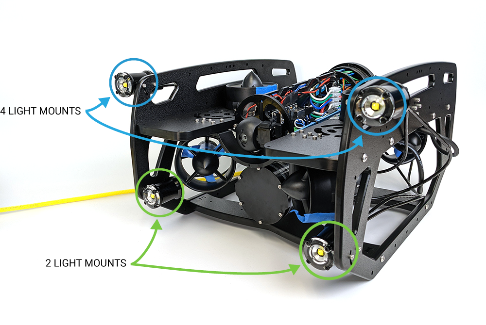
Mounting the Lights
To install the Lumen mounts you will need the following parts and tools:
- 1 x Assembled ROV frame
- 1 x Bag of M3x12 screws from box of Lumen Subsea Lights
- 1 x 2.5 mm hex driver
- 1 x Threadlocker
1. Find the bag of M3x12 screws included with the set of Lumen lights. Apply one drop of threadlocker to each of the M3x12 screws. Roll the screws around on a paper towel to evenly spread the threadlocker and to remove excess threadlocker.
2. Install the Lumens in the locations specified for the number of lights you have. Lights mounted in the upper mounting holes must be mounted on the outside of the frame. Lights mounted in the lower mounting holes can be installed inside or outside the frame according to preference. Installing the lights outside the frame reduces the amount of backscatter the camera sees but are less protected by the frame. Lights installed inside the frame are better protected but have slightly less tilt range. Route the cable that connects the lights on either side of the frame through the middle of the ROV, underneath where the Electronic Enclosure will go.
If you are installing Lumens in the top positions, do not secure them to the frame until after the thruster guards are installed in the next section.
3. Adjust the Lumens to the desired angle in the slot and tighten the screws. Be sure not to overtighten the screw that goes into the slot. Only tighten it so that it slightly indents the frame.
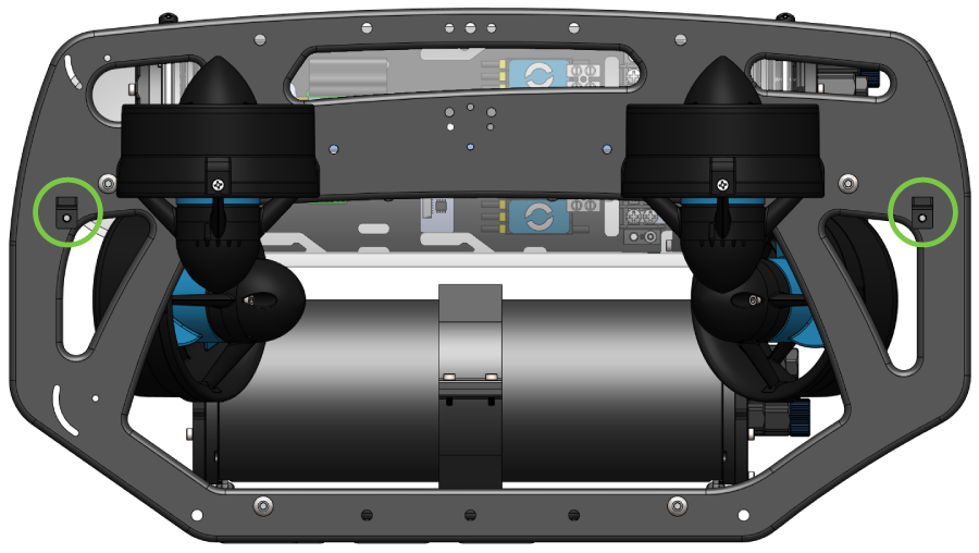
Installing the Thruster Guards
To install the thruster guards, you will need the following parts and tools:
- 8 x Heavy Guard Mounting Brackets (from Heavy Retrofit Kit)
- 2 x Heavy Thruster Guards (from Heavy Retrofit Kit)
- Bag of M4x16 screws (from Heavy Retrofit Kit)
- 1 x #2 Phillips head screwdriver
- 1 x 2.5 mm hex driver
- 1 x Threadlocker
1. Apply one drop of threadlocker to each of the M4x16 button head screws. Roll the screws around on a paper towel to evenly spread the threadlocker and to remove excess threadlocker.
2. Install four of the thruster guard mounting brackets (two on each side) on the outside of the frame using four M4x16 screws as shown below. The screws should go through the side panel first and thread into the brackets on the other side.
3. Place the thruster guards on top of the brackets and make sure the holes align. The thruster guards only install in one direction with the shorter leading edge of the guard oriented towards the front end of the vehicle. If you are installing Lumen lights in the top mounts, make sure to route the Lumen cable so it is inside the guard, near the front thruster mount. Secure the thruster guards to the brackets using four M4x16 screws. The screws should go through the thruster guards first and thread into the brackets on the other side.
4. Install four more thruster guard mounting brackets (two on each side) in the holes near the middle of the ROV using two M4x16 screws per bracket. The screws need to go through the frame or thruster guard first and screw into the bracket on the other side. Refer to the picture below.
5. Tighten all the screws evenly until they they indent the frame slightly.
Mounting Accessories to the Frame
At this point in the assembly you should mount any other accessories to the frame. Refer to the accessory’s installation guide for mounting instructions.
Adding Desiccant to the Electronics Enclosure
Desiccant will absorb humidity that is inside of the Electronics Enclosure to prevent the dome from fogging up during dives. It is especially useful if operating in humid environments with cold water. The desiccant will turn pink as it absorbs humidity.

1. Find the container of desiccant bags and place one bag in the Electronics Enclosure during the next step when reinstalling the Electronics Enclosure tube back on the flange. The following are recommended places to install the bag:
- In the space above the Fathom-X Tether Interface
- Zip tied to one of the long hex standoffs
- Tucked in the space next to the penetrator bulkheads
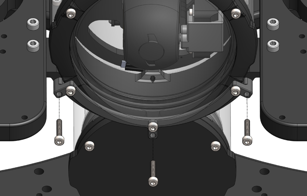
Mounting the Electronics Enclosure onto the Frame
To mount the Electronics Enclosure to the frame you need the following parts and tools:
- Electronics Enclosure assembly and ROV frame
- 1 x Electronics Enclosure tube
- 1 x Bag labeled “Electronics Enclosure Mounting Screws [4] M3x16”
- 1 x 2.5 mm hex driver
1. Apply silicone grease to the two radial O-rings on the rear Electronics Enclosure O-ring flange then install the Electronics Enclosure tube onto the flange. The rotation locking tab on the flange must sit in the slot in the tube to ensure everything is oriented correctly.
2. Insert the locking cord fully through the slot to lock the tube to the flange.
3. Install the PRV plug back into the PRV bulkhead to seal the enclosure.
4. Mount the Electronics Enclosure to the frame using the M3x16 Electronics Enclosure mounting screws so that the dome is on the same side as the front center panels (the center panels without the three large holes). Install the M3x16 screws through the mounting clips and into the front and rear enclosure cradles.
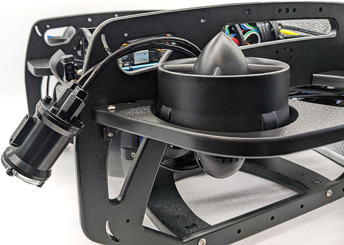
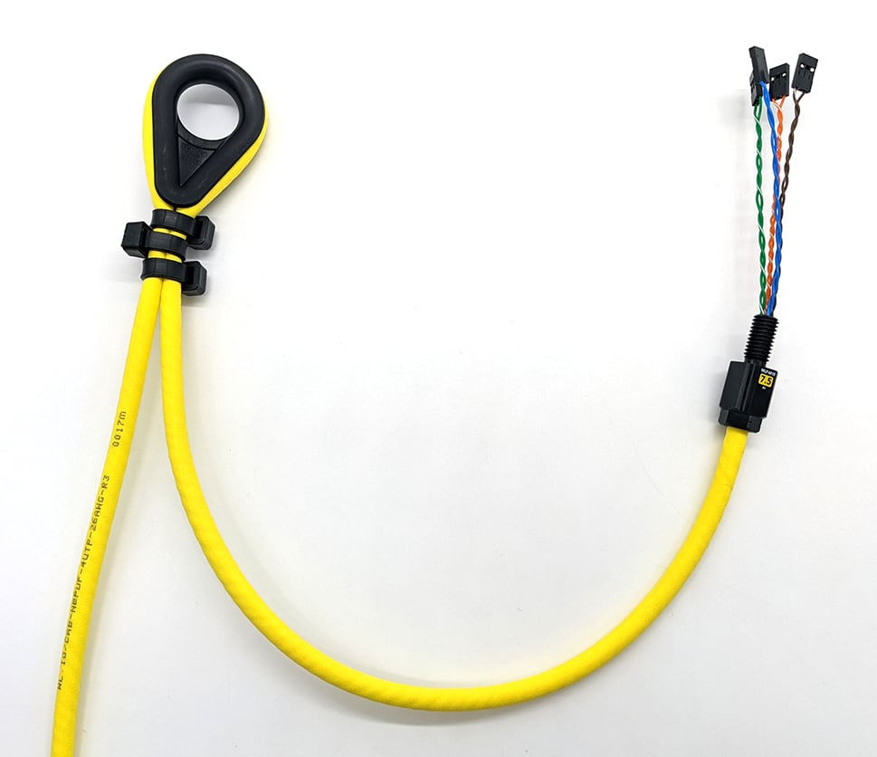
Mounting the Tether to the Frame
The tether needs to be firmly mounted to the frame to prevent the tether penetrator from being loosened during normal use. To do this, you will need the following parts and tools:
- 1 x Bag with thimble and five large zip ties
- 1 x Fathom Tether
- Assembled ROV frame
1. Loop the tether around the plastic thimble at a point about 12 inches (30 cm) away from the tether penetrator. If using Fathom Slim Tether, loop around the thimble twice.
2. Firmly attach three of the zip ties around the tether right at the base of the thimble, alternating directions as they are installed. Hold the tether tightly against the thimble until it is secured.
Regular Fathom Tether wrapped around the thimble.
Fathom Slim Tether wrapped around the thimble twice.
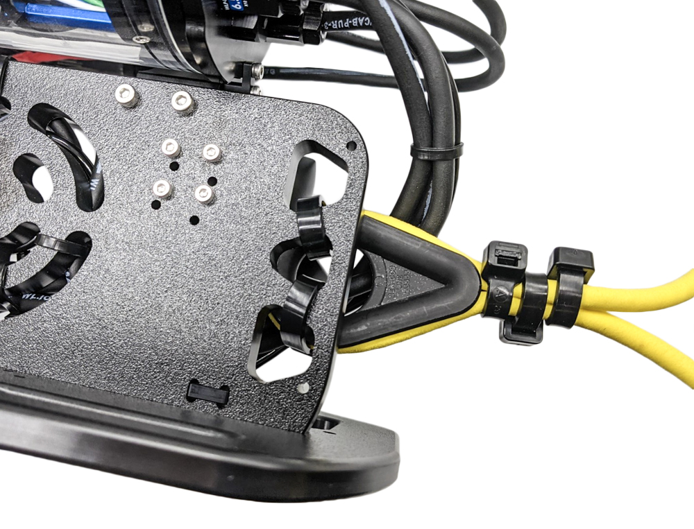
3. Use the remaining two large zip ties to attach the thimble to the rear panel as shown.
Cable Management
For this step you will need the included zip ties and your scissors/wire cutters.
The primary goal of cable management is to secure the cables to the frame to prevent them from getting damaged by the thruster propellers or getting caught on something during operation.
Secure the cables to the frame using the zip ties so there are no loose cables or loops that could get caught on something during operation. Make sure to check that no cables can reach a propeller after you have finished routing the cables. Below are some examples of what the cable routing should look like.
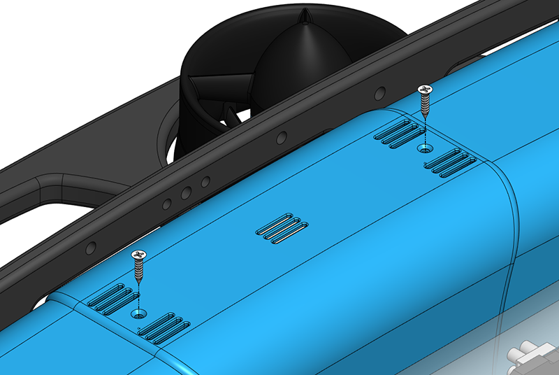
Installing the Fairings and Buoyancy
The buoyancy foam comes pre-installed in the fairings, but make sure it is still in all of the fairings prior to installation. To install the fairings, you will need the following parts and tools:
- 4 x Fairings with buoyancy installed
- 1 x Bag labeled “Blue Fairing Mounting Screws [16] #4-3/4”
- 1 x #2 Phillips head screwdriver
- 4 x Fairings with buoyancy installed
- 2 x Heavy additional buoyancy blocks
- 2 x Heavy fairings
- 1 x Bag labeled “Blue Fairing Mounting Screws [16] #4-3/4”
- 1 x Bag of flat head fairing screws (from Heavy Retrofit Kit)
- 1 x #2 Phillips head screwdriver
1. Install the fairing mounting screws through the center panels and into the fairings.
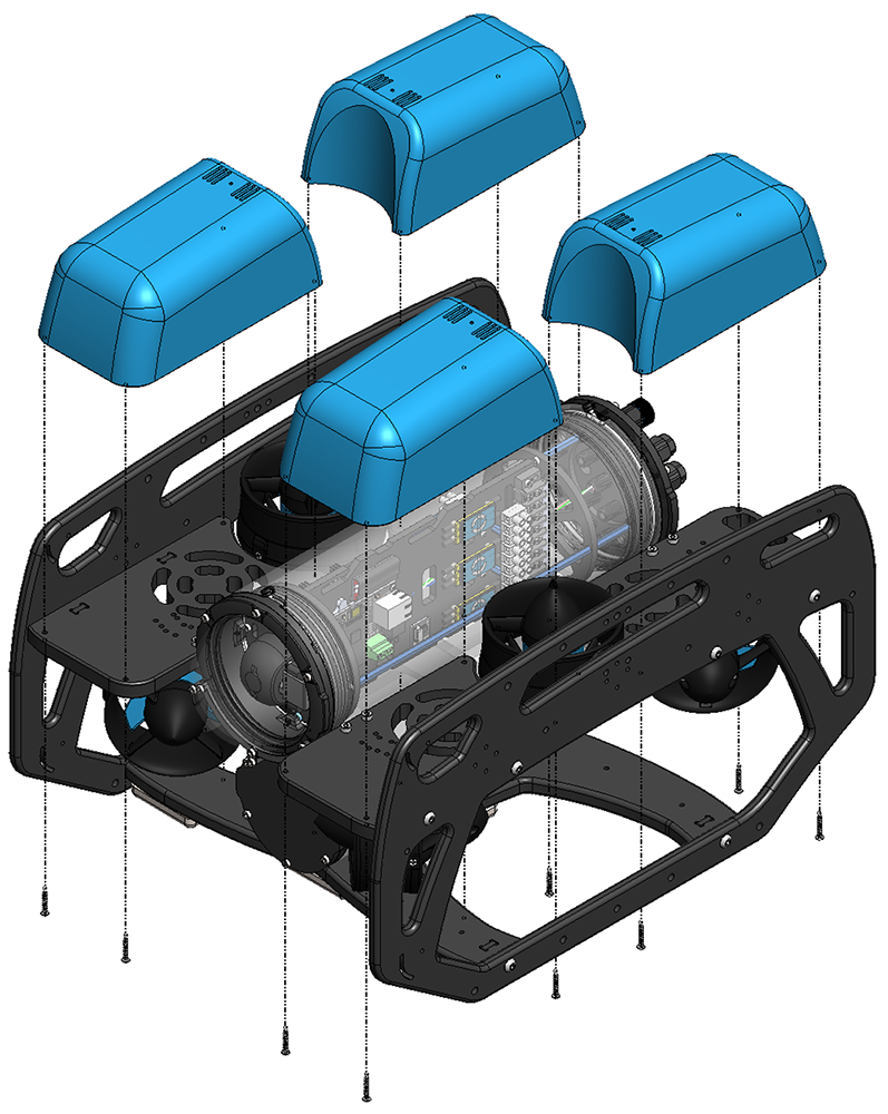
2. Place the round buoyancy blocks from the Heavy kit into the open space between the fairings. Ensure the flat sides of the blocks are parallel to the sides of the ROV.
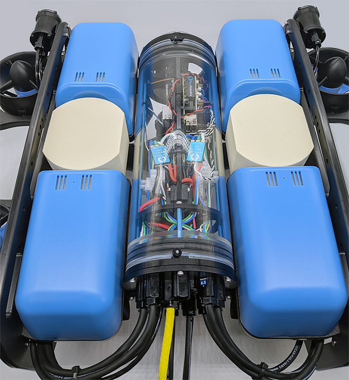
3. Place the Heavy fairings on top of the buoyancy blocks and secure them to the previous fairings using the flat head fairing screws from the Heavy Retrofit Kit.
Adjusting the Ballast
To adjust the ROV ballast, you need the following parts and tools:
- 1 Box with ballast weights
- 1 Bag labeled “Ballast Mounting Screws [9] 8-18”
- 1 x #2 Phillips head screwdriver
- 1 Box with ballast weights
- Additional ballast weights from Heavy Retrofit Kit
- 1 Bag labeled “Ballast Mounting Screws [9] 8-18”
- 1 Bag of ballast mounting screws (from Heavy Retrofit Kit)
- 1 x #2 Phillips head screwdriver
For the longest battery life and the best driving experience, it is important to have the ROV floating level and as close to neutrally buoyant as possible in the water. When we say “neutrally buoyant”, it means the ROV will neither float up or sink, but remain suspended at the same level. If the ROV is not level or is excessively buoyant in either direction, it will need to work harder to stabilize and maintain depth during operations, resulting in reduced battery life. Ballast weights positioned under the ROV can be added, removed, or repositioned to achieve the desired balance.
1. Use the #2 Phillips screwdriver and the ballast mounting screws to mount the weights in the holes under the bottom frame panel. Start with the ballast weight configuration shown below, but keep in mind the final number of weights and their location on the frame depends on your ROV configuration and installed accessories.
Adjusting the ballast requires that the ROV is floating in water. A good time to adjust the ballast is during your first test dive, in calm water and a controlled environment.
1. Make sure the ROV enclosures are sealed and the PRV or vent plugs are properly installed. Place the ROV in calm water, a medium-size pool is best. The ROV should have enough room for you to be able to see how it naturally floats in the water. The ROV should be powered off or disarmed while you adjust the ballast.
2. Check how the ROV is floating in the water. The ROV should not be tilting or pitching to any side. If it is, add, remove, or relocate the ballast weights as needed to get the ROV to float level in the water.
3. The ROV should also not quickly sink or float up to the surface of the water. Push the ROV half an arm’s length under the water and let go, it should not sink or rise but maintain its current level. Add or remove ballast weights to achieve neutral buoyancy.
Adjusting the ballast involves some trial and error but is crucial for achieving stability, control, efficiency, and safety during underwater operations.
Next Steps
Your BlueROV2 should now be fully assembled and ready to connect to your computer. To continue with the setup process, proceed to the BlueROV2 Software Setup guide.
BlueROV2 Software Setup
Issue Reporting
We’re always trying to make our documentation, instructions, software, and user experience better. If you’d like to leave feedback about how we can make this guide better, let us know here. If you’re having an issue with anything, please report it so that we can address it as soon as possible! Here’s where to do that depending on what’s wrong:
- ArduSub Issues: For anything related to the ArduSub software that runs on the Pixhawk and controls the ROV, reports issues on the ArduSub Github Issues Page. If you’re unsure where your issue should be posted, you can report it here.
- QGroundControl Issues: For anything related to the QGroundControl software, joystick setup, video streaming, etc., please report an issue on the QGroundControl Github Issues Page.
- Documentation: For anything related to the documentation and instructions here, please report an issue by submitting an e-mail to [email protected].