
Integrating the Omniscan 450 SS on the BlueBoat
The Cerulean Omniscan 450 SS seamlessly integrates with the BlueBoat to provide side scan sonar imaging to help you locate and identify underwater objects and map the seafloor. This guide will show you how to install it on the BlueBoat.

Kit Contents
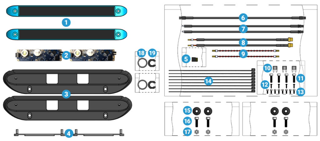
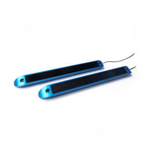
- 2 x Cerulean Omniscan 450 SS transducer
- 2 x Cerulean Omniscan 450 SS PCB
- 2 x Aluminum transducer bracket (BR-102204)
- 2 x Aluminum PCB standoff (BR-102498)
- 1 x BlueOS 128GB SD card for BlueBoat (BR-102293-002)
- 1 x Micro-Fit Ethernet cable, 1.1 m (BR-102172)
- 2 x Micro-Fit to JST GH cable, 0.32 m (BR-102122)
- 2 x E-Tray transducer cable (BR-102212)
- 2 x 2-position ferrules to ferrules power cable, 150 mm (BR-102196)
- 3 x 5A Mini Blade fuse (BR-101401-005)
- 4 x M5x18 socket head cap screw (BR-101191)
- 4 x #3×3/8″ button head thread forming screw (BR-101031)
- 8 x M3x8 socket head cap screw (BR-100989)
- 8 x 8.5″ cable tie (BR-102154)
- 4 x BlueBoat Hull Mount Bushing
- 4 x M6x20 socket head cap screw (BR-102241)
- 4 x M6 nylon insert lock nut (BR-101258)
- 2 x -117 bulkhead O-ring (BR-100635-117)
- 2 x M14 bulkhead nut (BR-100845)
Parts and Tools for Installation
In addition to the Omniscan kit, you will need the following to complete the installation:
- 2.5 mm hex driver
- 4 mm hex key (included in BlueBoat kit)
- 5 mm hex key (included in BlueBoat kit)
- #1 Phillips screwdriver
- Small (~2 mm) flathead (slotted) screwdriver
- M14 Bulkhead Wrench
- Silicone grease (Molykote 111)
- 1 x JST GH to JST GH twisted pair cable (from Ethernet Switch kit)
Preparing the SD Card
The Cerulean Omniscan 450 SS kit includes a 128GB SD card that provides more storage space to log sonar data files directly on the BlueBoat. It comes pre-loaded with BlueOS configured for BlueBoat and replaces the 16GB SD card that is already installed in the BlueBoat. Using this larger SD card is optional. You may continue using the 16GB SD card in your boat, but be aware that it offers less storage space for logging sonar output. You can also switch out the SD card at a later time.
If you choose to use the 128GB SD card, you have a couple of options:
- You can install the 128GB SD card as is and start with a fresh BlueOS system. Starting with a fresh BlueOS system will require you to reconfigure settings, recalibrate sensors, and reinstall updates and extensions. If you are already starting with a new, unconfigured BlueBoat anyway, this would be the easiest option.
- You can clone your SD card to preserve your current BlueOS system configuration, with all settings and installed extensions intact. If you would like to clone your SD card, follow the steps in the ‘Cloning the SD Card’ section below.
Cloning the SD Card
“Cloning” an SD card involves copying all data from one card to another, creating an exact duplicate of the original. To do this, we recommend using Balena Etcher. You will also need an SD card reader/writer. Some laptops have one built-in, but you can also use a USB one.
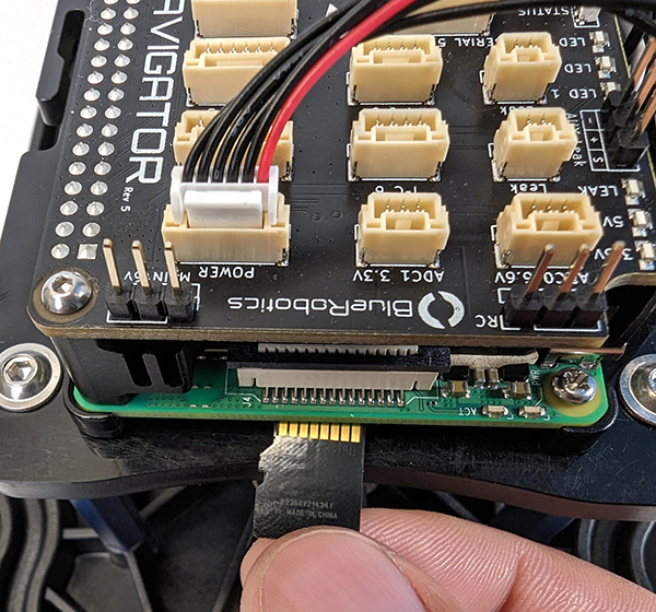
1. Open the starboard side hatch lid assembly to remove the micro SD card from the Raspberry Pi. A pair of tweezers is helpful for this.
2. Download and install Balena Etcher.
3. Insert the micro SD card from the BlueBoat and the 128GB SD card from the Cerulean Omniscan 450 SS kit into your computer.
4. Open Balena Etcher and choose the Clone drive option.
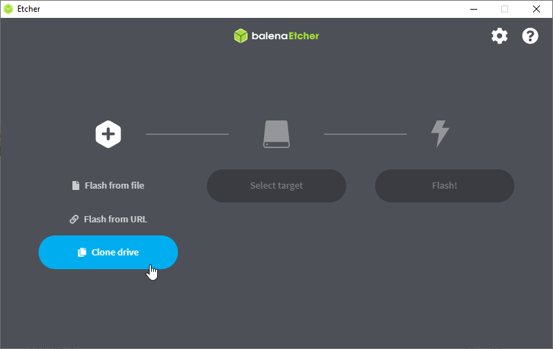
5. Select the 16 GB SD card as the source, then choose the 128GB SD card as the target. Click on Flash! to clone the card and wait for the process to finish.
At the end of this process, you will have two micro SD cards with duplicated data. Insert the 128 GB micro SD card into the BlueBoat Raspberry Pi. The old 16 GB card can be stored as a backup. Proceed to the next steps.
Hardware Installation
Preparing the BlueBoat
1. Disconnect all the cables that connect the starboard and port hatch lid assemblies to the BlueBoat. Remove both assemblies from the BlueBoat.
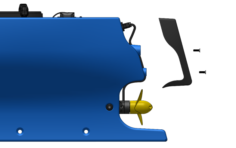
2. Use the 4 mm hex key to remove the hull fairing screws and remove the fairings from the hulls.
3. Use the M14 Bulkhead Wrench to loosen the C-nut holding the blank penetrator inside the hull. Remove the blank penetrator from both hulls.
Mounting the Transducers
To mount the transducers, you will need:
- 2 x Cerulean Omniscan 450 SS transducer
- 2 x Transducer bracket
- 4 x BlueBoat Hull Mount Bushing
- 4 x M6x20 socket head cap screw
- 4 x M6 nylon insert lock nut
- 2 x M14 bulkhead nut
- 2 x -117 Bulkhead O-ring
- 5 mm hex key
- Molykote 111 silicone grease
- 4 x 8.5″ Cable tie (BR-102154)
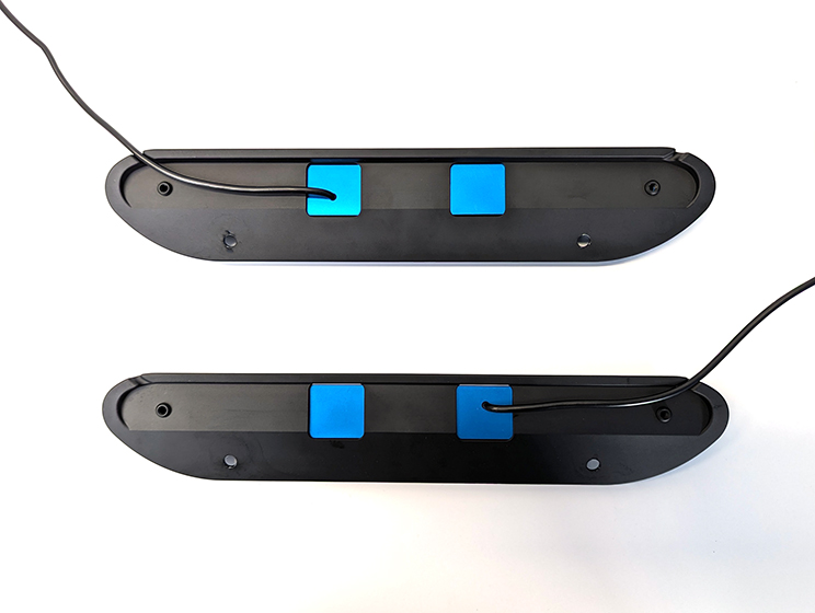
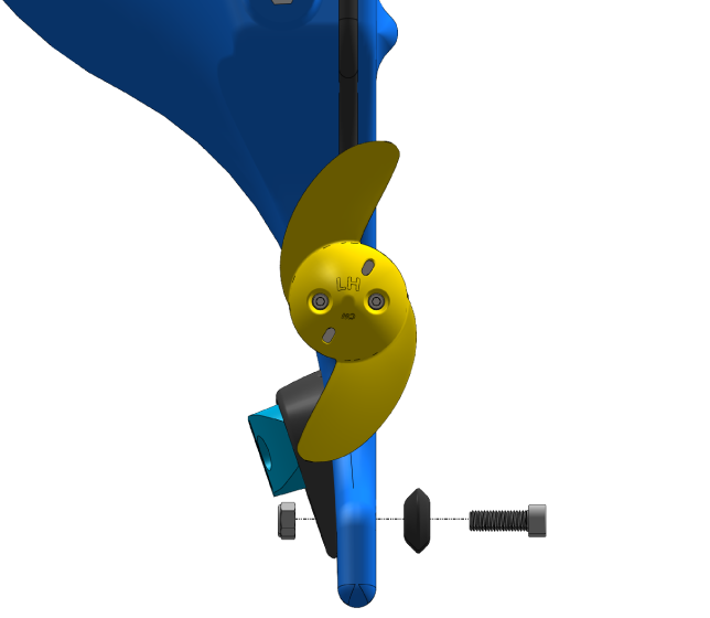
1. Install the transducers in the brackets. Orient the transducers so that one of the cables is routed through the left-side cutout in the bracket and the other transducer uses the right-side cutout. The transducers and brackets are identical so it does not matter which side is which.
2. Secure the transducers to the brackets using the M5x18 socket head cap screws and the 4 mm hex key. Tighten to around a ¼ turn past snug.
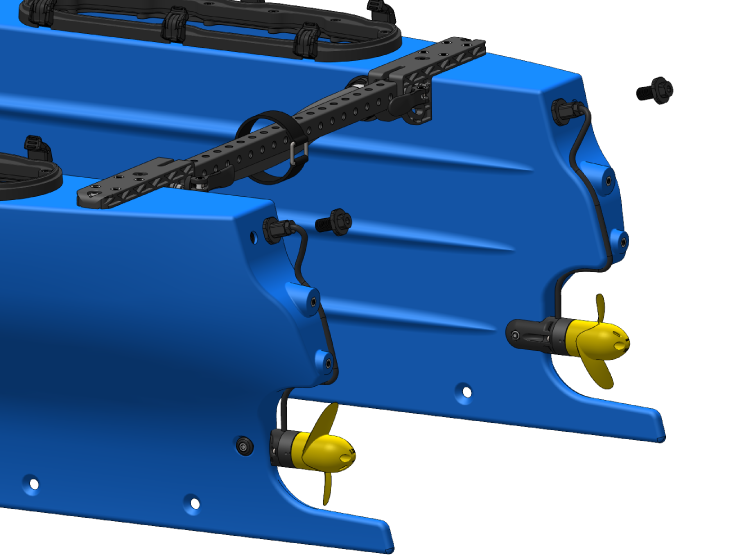
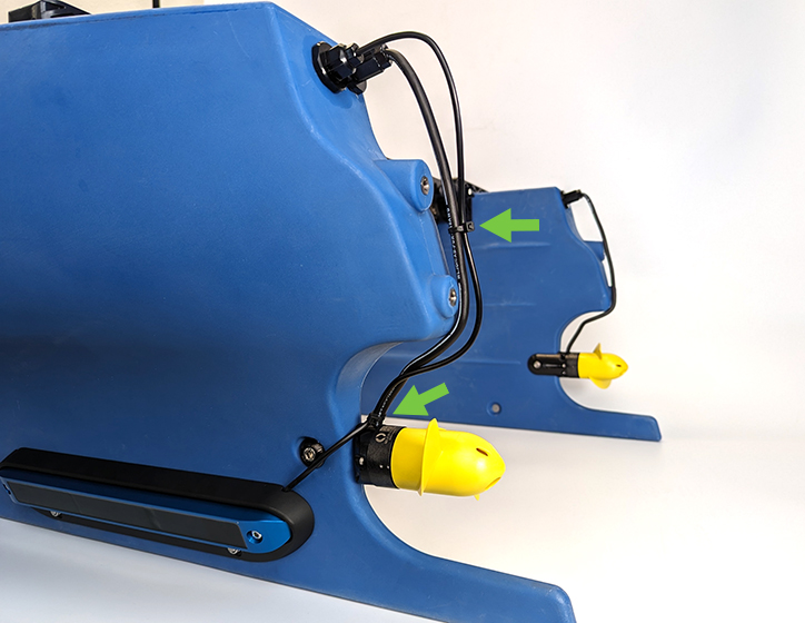
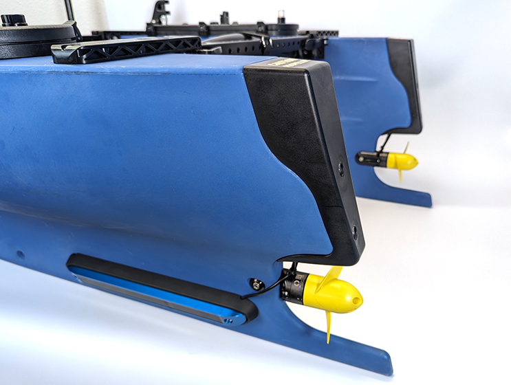
3. Use the hull mount bushings, M6x20 socket head cap screws, M6 nylon locknuts, and 5 mm hex key to install the transducer brackets to the hull mounting holes closest to the rear of the boat. Install the transducer brackets so they face outwards from the hulls. When installing on a hull, use the transducer assembly whose cable exits the bracket closest to the rear. Do not fully tighten the screws until both screws are in place.
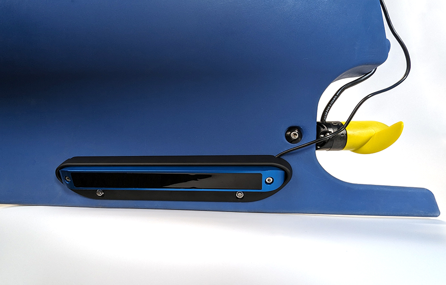
Ensure the bottom of the transducer bracket is parallel to the bottom of the hull and the cable is routed through the cable cutout before fully tightening the screws.
4. Apply a thin, even coat of Molykote 111 silicone grease to the O-rings and install one in the groove under each bulkhead.
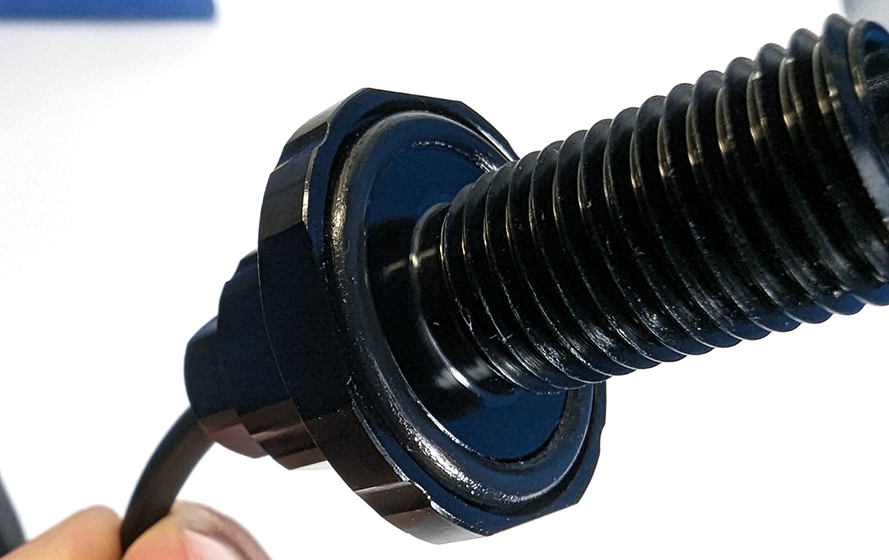
5. Install the bulkheads in the holes where you removed the blank penetrators previously. Use the M14 Bulkhead Wrench to tighten the C-nut to the bulkhead inside the hulls.
6. Use the included cable ties to secure the cable to the M200 cable. Use a cable tie at the base of the M200 cable and another midway up the cable. Cut off the excess.
7. Install the fairings back on the hulls.
Installing the Electronics
To install the electronics you will need:
- 2 x Cerulean Omniscan 450 SS PCB
- 2 x Aluminum PCB standoff
- 2 x Micro-Fit to JST GH cable, 0.32 m
- 2 x E-tray transducer cable
- 2 x 2-Position ferrules to ferrules power cable, 150 mm
- 2 x 5A Mini Blade fuse
- 8 x M3x8 Socket head cap screw
- 4 x #3 x 3/8″ Button head thread forming screw
- 2.5 mm hex driver
- #1 Phillips screwdriver
- Small (~2 mm) flathead (slotted) screwdriver
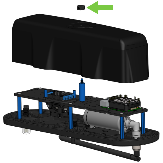
1. Take the cover off the starboard side hatch lid assembly.
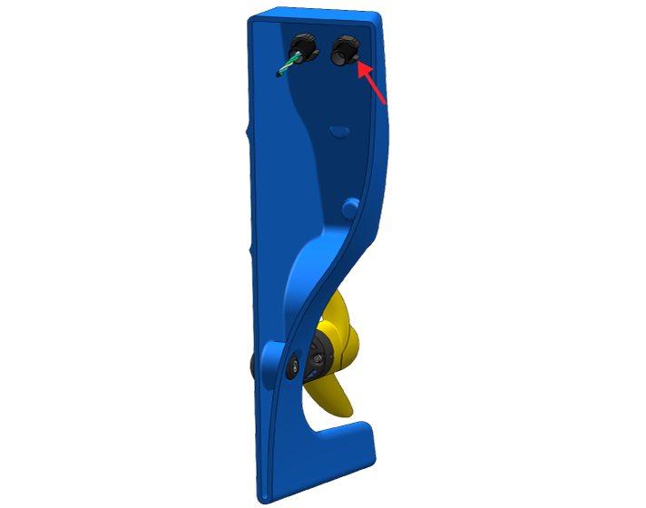
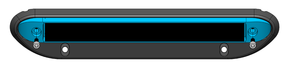
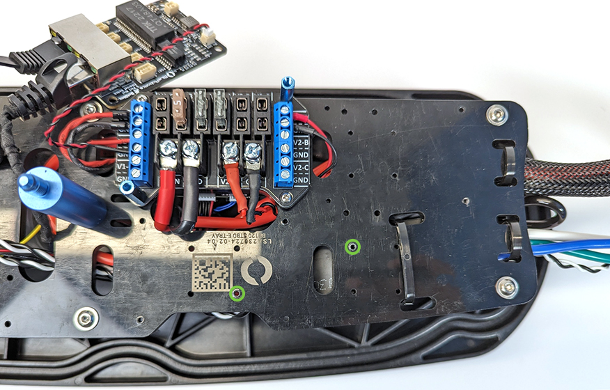
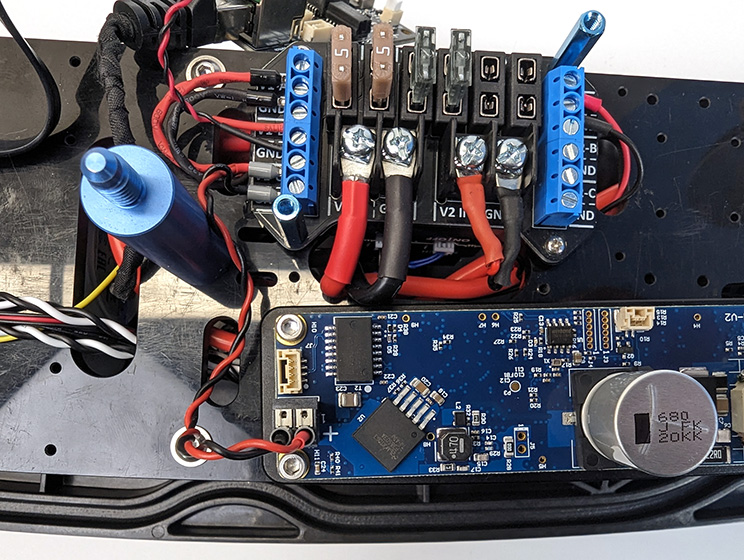
2. Mount the aluminum PCB standoff to the electronics tray using the holes shown below and two thread-forming screws. The standoffs are identical, so it doesn’t matter which one you use. Align the curved side of the standoff with the curved edge of the electronic tray. This will align two of the mounting holes with the holes in the electronics tray.
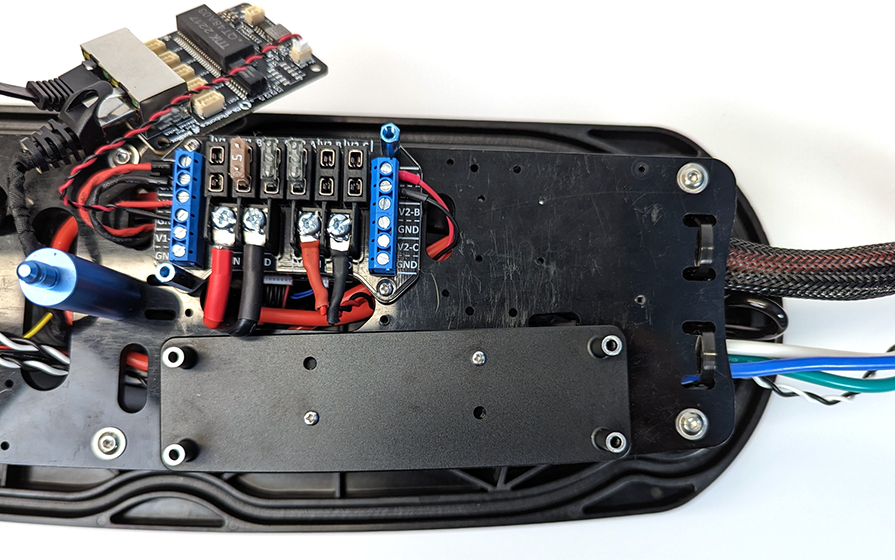
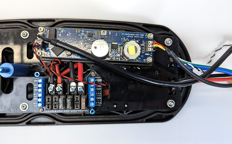
3. Install a PCB on the standoff using the M3x8 socket head screws and the 2.5 mm hex driver. The PCBs are identical, so it does not matter which one you choose. Install the PCB with the 3-position connector on the same side as the cables.
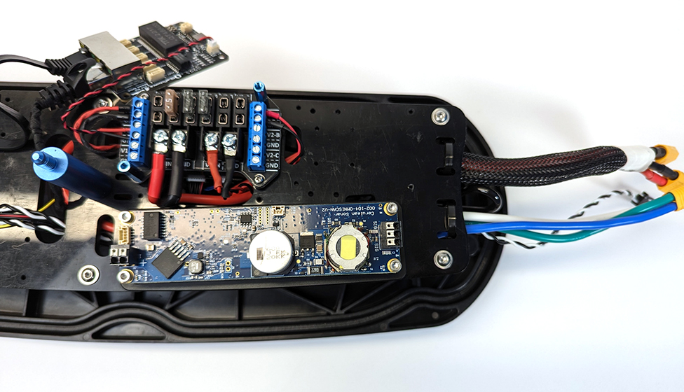
4. Connect one of the ferrule to ferrule power cables to an available output on the V1 side of the fuse board (V1-A, V1-B, or V1-C, whichever is available). Do not use the V2 side as this side only supplies 5 V power. Connect the black wire to the position labeled “GND” and the red wire to the voltage output next to it. Use the small flathead screwdriver to loosen and tighten the connectors.
5. Install one of the included 5A mini blade fuses into the corresponding slot at the top of the fuse board.
6. Connect the other end of the power wires to the 2-position connector on the PCB. Connect the red wire to the side labeled “+”. Simply push the ferrule into the connector to connect it.
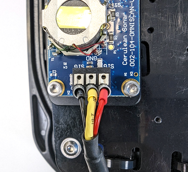
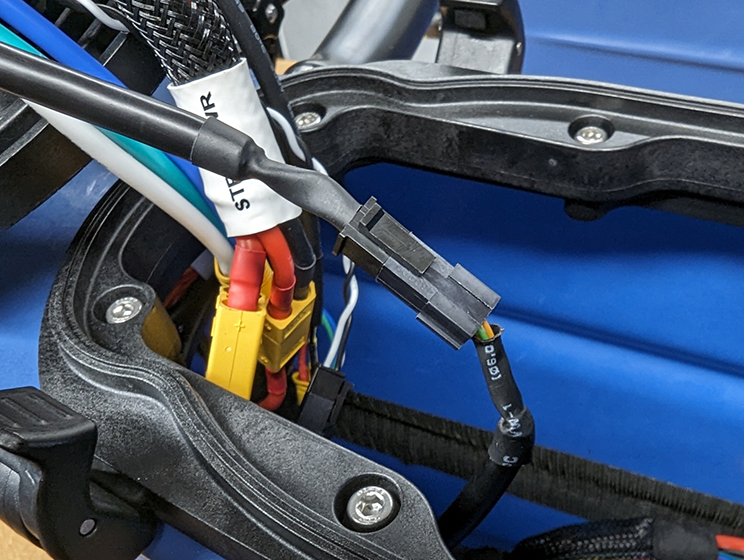
7. Connect the transducer cable ferrules to the 3-position connector on the transducer PCB. The 3 positions are labeled “SIG – GND – SIG”. Connect the yellow wire to the middle “GND” position and the red and black wires to the “SIG” positions. It does not matter which side the red or black wires are on, just make sure the yellow wire is in the middle.
8. Repeat steps 1 through 7 for the port side hatch lid assembly.
Additional steps for starboard side hatch only
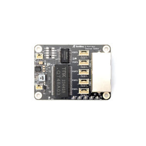
Now is a good time to install the Blue Robotics Ethernet Switch if you have not done so already. Follow the installation guide to install the switch, then come back to this guide when you are done. TIP: the Cerulean Omniscan 450 SS kit includes an extra 5A fuse for installing the Ethernet Switch. If you have previously installed the switch, go ahead and mount it back onto the fuse board at this time.
1. Use a JST GH to JST GH twisted pair cable from the Ethernet Switch kit to connect the transducer PCB to port 2 (or 3 or 4) on the switch. Do not use ports 1 or 5 as these are already in use.
2. Connect one of the JST GH to Micro-Fit cables to port 3 (or 2 or 4) on the switch. Do not use ports 1 or 5 as these are already in use.
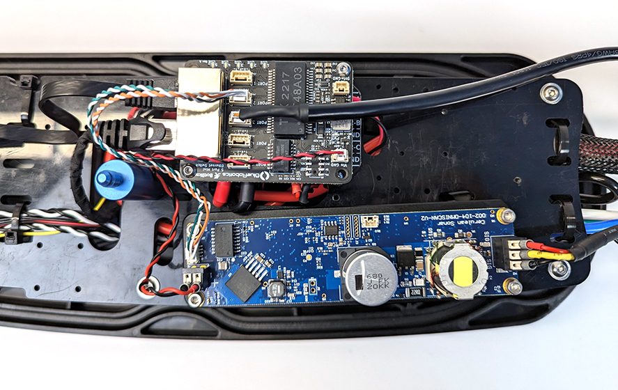
3. Use 2 cable ties to secure the transducer cable and Micro-Fit cable to the electronics tray cut outs or to the other cables.
4. If you are replacing the SD card, remove the old SD card from the Raspberry Pi (some tweezers are helpful here) and install the new 128GB SD card. Skip this step if you will continue using the current SD card.
Additional step for port side hatch only
1. Connect the other Micro-Fit cable to the JST GH port on the transducer PCB.
2. Use 2 cable ties to secure the transducer cable and Micro-Fit cable to the electronics tray cut outs or to the other cables.
Connecting the Cables
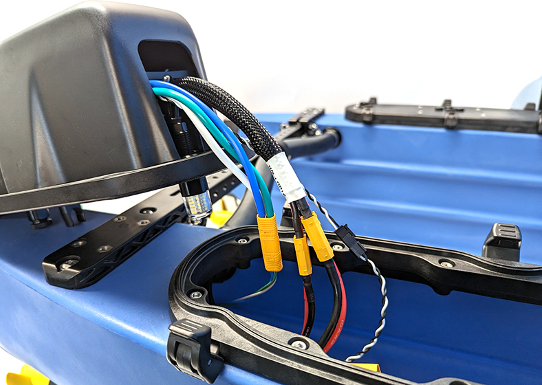
1. The long Micro-Fit Ethernet cable is used to connect the transducer PCB in the port side to the Ethernet Switch in the starboard side. Pass this cable through the crosstube.
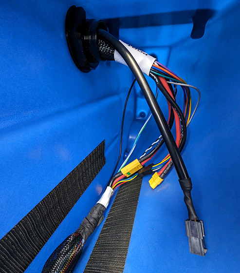
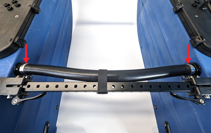
If this is difficult, you can loosen the hose clamps to temporarily remove the tube. Using a wire clothes hanger or electrician’s fish tape is also helpful to get the cable through the tube.
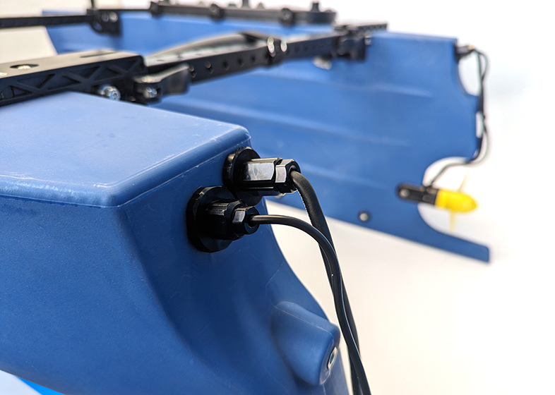
2. After the long Micro-Fit cable has been passed through the crosstube, connect the port side of the cable to the Micro-Fit cable coming from the port side hatch. Do not connect the starboard side of the Micro-Fit cable yet. You can now also connect all the other cables that connect to the hatch lid assemblies, including both transducer cables coming from the rear of each hull.
3. Proceed to the software setup.
Software Setup
Initial Setup
1. Power up your BlueBoat and BaseStation and connect it to your computer. If you don’t know how to do that, please check out the BlueBoat Software Setup guide first.
2. Access BlueOS (the BlueBoat’s operating system) by typing 192.168.2.2 or blueos.local into a web browser address bar.
3. Connect the BlueBoat to a Wi-Fi network.
4. How you proceed next depends on whether you are using a fresh install of BlueOS on the 128GB SD card or you copied over your existing SD card image to the 128GB SD card.
- If you are using a fresh installation of BlueOS, click on “I am using a fresh install” below.
- If you copied your existing SD card, click on “I copied my existing SD card” below.
- If you did not replace the SD card in the BlueBoat, you can skip this step and continue directly to setting up the SonarView extension.
I am using a fresh install I copied my existing SD card
Complete the new BlueBoat software setup process starting from the Update Software section of the software setup Guide. Come back to this guide when you have completed setting up your BlueBoat.
The Raspberry Pi system image needs to be expanded to make use of the full capacity of the larger SD card. Fortunately, BlueOS already has a built-in utility to do just that:
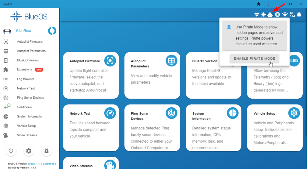
1. From BlueOS, enable Pirate Mode by clicking the happy robot icon in the top right corner.
2. With Pirate Mode enabled, click on Terminal from the left sidebar. Type in “red-pill” and press enter.
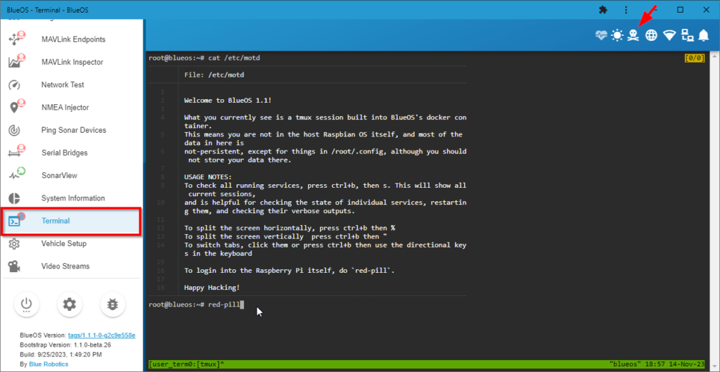
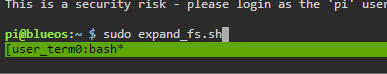
3. You will see a few lines of text, then the terminal will wait for user input again. Copy and paste or type in the following command then press enter: sudo expand_fs.sh
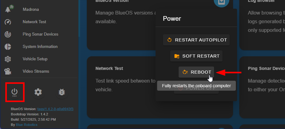
4. The process will take a few minutes, you will know when it is done when the terminal goes back to waiting for user input. once it’s done use the BlueOS power menu and select REBOOT to fully reboot the system.
Once the system is rebooted the full capacity of the SD card is now available to use (you can double check this by looking at the Disk information on the BlueOS System Information page). Continue to setting up SonarView.
Setting up the SonarView Extension
1. The Cerulean Omniscan 450 SS requires BlueOS stable version 1.1.0 or later. If your system is out of date, follow these instructions to update BlueOS then come back to this guide.
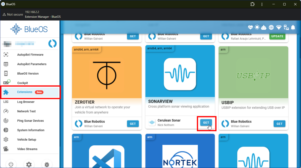
2. Go to the Extensions menu in BlueOS and install the SonarView extension by Cerulean Sonar.
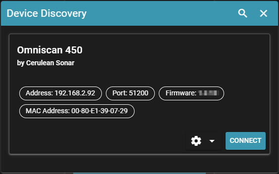
3. Click on the SonarView extension from the left sidebar and go to Device Discovery.
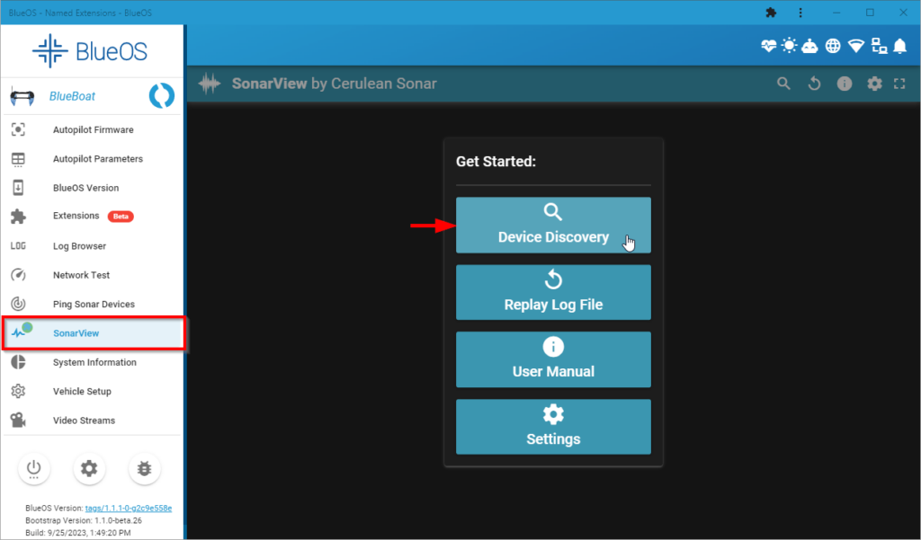
You should see a screen like this, showing that the starboard side transducer PCB is detected.
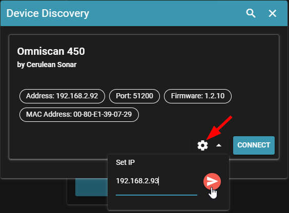
4. Click the settings icon and set the IP address to 192.168.2.93, click the arrow icon to set the IP address.
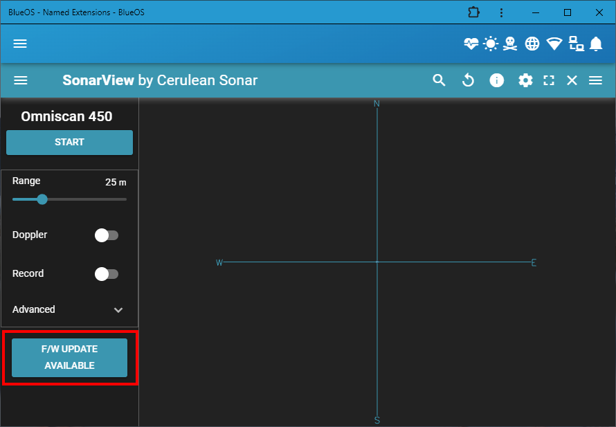
5. After the IP address has been set, click CONNECT. If the F/W UPDATE AVAILABLE button appears at the bottom of the left side device controls, update the firmware. If it does not appear, the device already has the latest firmware or your BlueBoat is not connected to the internet. The BlueBoat must have an internet connection in order to check for updates.
6. Close the SonarView session by clicking the X icon at the top of the SonarView window. Go back to the BlueBoat starboard side hull and connect the Micro-Fit cable from the hatch lid assembly to the Micro-Fit cable in the crosstube.
8. Go back to Device Discovery in SonarView, you should now see two devices: the starboard side PCB at IP address 192.168.2.93 and the port side PCB at IP address 192.168.2.92. Connect to the port side PCB at 192.168.2.92 and update the firmware if an update is available.
Creating a Session Configuration
Now that each transducer PCB has a unique IP address, we must setup a session configuration to use both transducers simultaneously:
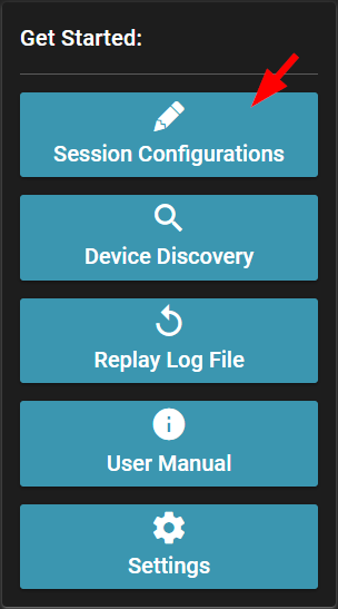
1. From the SonarView main menu, click on Session Configurations.
2. In the Session Configurations screen click on ADD DEVICE. In the next window, click on Detect Devices and you should see each connected transducer PCB and its IP address.
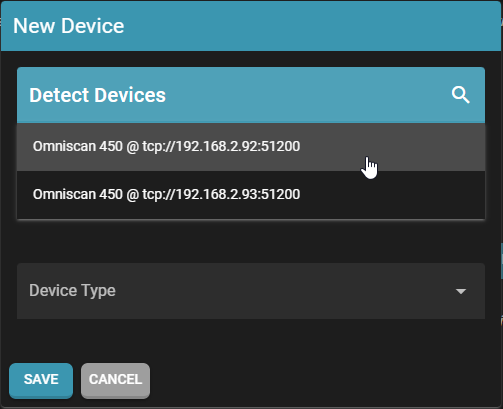
3. Start with the port side at 192.168.2.92:51200 and click on it.
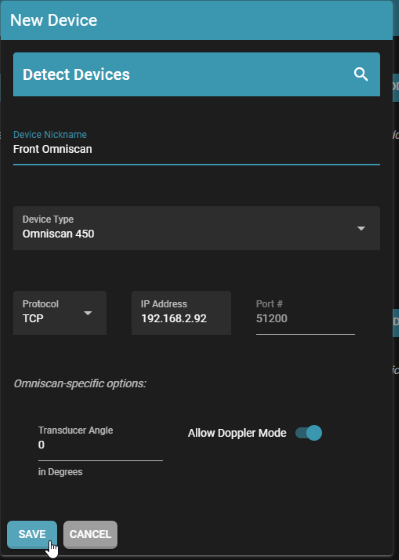
- On the next screen, give a name that will help you distinguish it, “port omniscan” for example.
- Set the Transducer Angle to -90.
- Leave the other settings at their defaults. Click on SAVE when you are done.
Now configure the starboard side at 192.168.2.93:51200.
- Give a name that will help you distinguish it, “starboard omniscan” for example.
- Set the Transducer Angle to 90. Take note, this is different from that port side angle!
- Leave the other settings at their defaults. Click on SAVE when you are done.
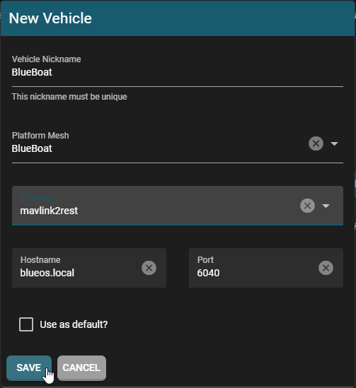
4. While still in Session Configurations screen, click on ADD VEHICLE.
- Enter a vehicle nickname, “BlueBoat” for example, but this could be anything you want.
- The Platform Mesh is the model used in the SonarView display. Set it to BlueBoat for an accurate look.
- Set the Protocol to mavlink2rest.
- Click on SAVE when you are done.
5. Click on ADD SESSION to make a new session. On the next screen, give the session a name, “Dual Omniscans” for example. Use the drop downs to add the BlueBoat and both Omniscans to the session. Click on SAVE when you are done.
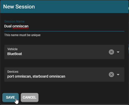
That’s it! This session will now appear in the Device Discovery menu. Click on CONNECT next to the session then START to start pinging.
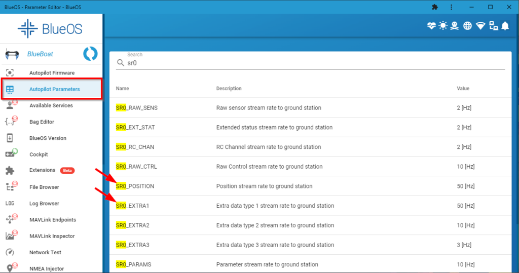
Adjust Message Stream Rates
1. In BlueOS, click on Autopilot Parameters.
2. In the search box, type “sr0”. Find the SR0_POSITION and SR0_EXTRA1 parameters and set them both to “50”.
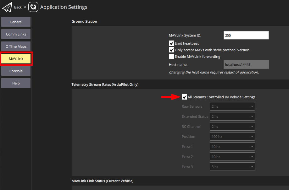
Configure QGroundControl
QGroundControl needs to be configured to allow the vehicle to control message rates.
Open QGroundControl, click the Q icon in the top left corner, then click Application Settings.
Click MAVLink on the left side, then enable All Streams Controlled By Vehicle Settings. Restart QGroundControl.
The Omniscan 450 SS is now ready to use!
Using the Omniscan 450 SS
This section will go over some of the basics of using the Cerulean Omniscan 450 SS with the BlueBoat. You can also check out Cerulean Sonar’s Omniscan and SonarView documentation for more information.
SonarView can be installed as an extension in BlueOS.
1. With the BlueBoat powered on and connected to your computer, start SonarView and click Device Discovery.
2. The session you created should appear in this menu, click on CONNECT. You’ll be taken to the main user interface.
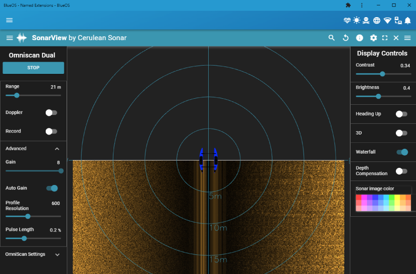
The user interface has the Omniscan device controls on the left, the sonar output image in the middle, and the display controls on the right.
Interpreting the Sonar Image
Side scan sonar images can be challenging to interpret if you don’t know what you’re looking at. This section will cover some of the basics.
“So what exactly am I looking at?”
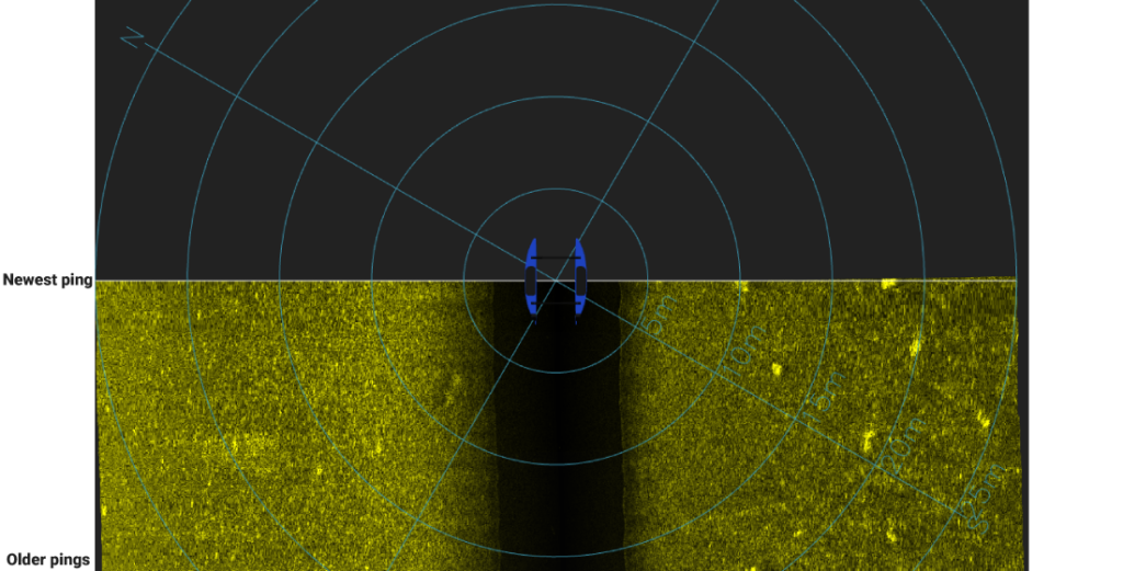
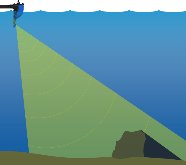
The side scan sonar creates an image by transmitting fan-shaped pulses of sound (pings), then listening to the echoes that are reflected from the bottom back to the system. The pings are recorded to create slices of an image drawn one on top of the other in the sonar output, and as the BlueBoat travels through the water, the image of the seafloor is filled in.
The Water Column
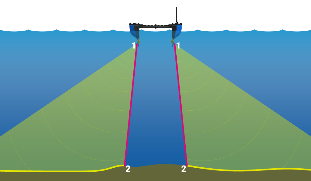
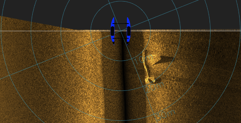
Notice the dark area in the middle of the sonar image above. It may look like missing information from the sonar image, but this is not the case. As the sound pulse is emitted from the transducer (#1 in the image below) and travels through the water, no echoes have been reflected back to the system yet. This lack of echoes as the sound travels through the water results in the dark area in the middle of the sonar output image. This area is known as the water column.
The first received echoes on the sides of the water column (#2) are reflections from the area underneath the transducer. In the figures below, the areas are colored to show how they correspond to the sonar output image.
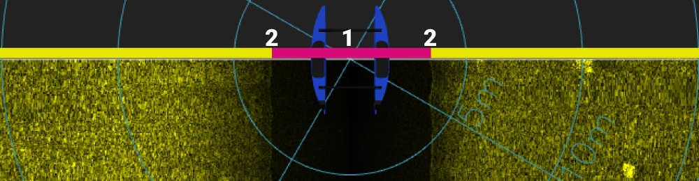
In deeper water, the water column will appear wider. The depth of the water column beneath the transducer can be determined by measuring the width of the water column as it is displayed in the sonar image. In the image above, we can see the depth of the water is a little under four meters.
Slant Range vs Horizontal Range
The distances overlaid on the sonar image are slant ranges, which is the direct distance from the sonar transducer. This distance is measured diagonally along the line of the sonar signal’s travel, it is not the horizontal distance from the side of the BlueBoat. The true horizontal distance of an object from the side of the boat will be less than the slant range shown.
Look for the Shadows
In side scan sonar images, objects can often be most easily identified by their shadows. These “acoustic shadows” occur when an object on the bottom blocks the area behind it, preventing echoes from that area. The shape and length of these shadows help to highlight the objects and also provide information about their height and size, with taller objects casting longer shadows.
In the example below, you can distinctly see the shape of the sunken airplane from the long shadows cast by the wing and stabilizer protruding from the muddy bottom.
Reflection Brightness
A basic rule of thumb is that hard objects like rocks, concrete, metal, or shipwrecks, reflect more sound and appear brighter in the sonar image. Softer materials like silt, sand, or mud reflect less sound and appear darker.
Device and Display Controls
Device Controls
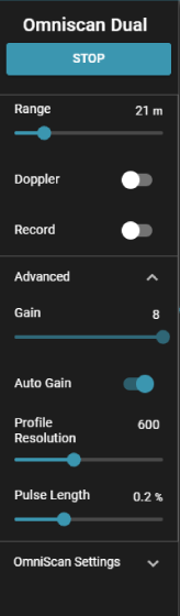
- START/STOP: Click the button to start pinging. Click it again to stop pinging. Do not leave the Omniscan 450 pinging for long periods of time when out of the water. The transducer will heat up gradually and could be damaged. Several minutes at a time should be fine.
- Range: Sets the maximum distance, on either side of the BlueBoat, that is displayed in SonarView. Note that this is the slant range, not the horizontal range from the transducers.
- Record: Enables or disables automatic saving to a SonarView log file. When this is enabled, sonar data is saved to the /userdata/SonarView directory in BlueOS.
- Advanced Controls: The default values for the advanced controls are recommended for normal operation. An explanation of their function is available in the SonarView documentation.
Display Controls
The following settings affect how the sonar image is displayed. More information about any setting can be found in the SonarView Documentation.
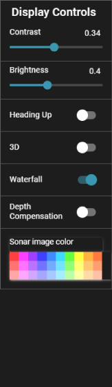
- Contrast and Brightness: The default settings work well in most situations, but can be adjusted to optimize the image. Generally lower contrast is better when trying to find weak signals.
- Heading up: When this is enabled, the display will rotate to follow the BlueBoat heading.
- 3D: Enables a three dimensional view.
- Waterfall: Waterfall view is the way side scan data is typically displayed on sonar systems.
- Depth Compensation: Removes the blank water column or “nadir” from the middle of the sonar image.
Operation Tips
Water Conditions
- The best quality sonar data is collected when the water and weather conditions are calm. Because the transducers are fixed to the BlueBoat hulls, pitching movement from waves and choppy water will distort the sonar image.
- Rough water will make it difficult to resolve smaller targets, but you may still be able to locate large objects. Figure 1 on the left below shows scans of a 94 meter long ship during a windy day with lots of waves. While the image appears heavily distorted, the ship was still able to be located. Figure 2 on the right shows the same ship scanned on a day with better conditions. Because the ship’s location was found during the previous survey, a smaller, more precise survey could be conducted the second time.
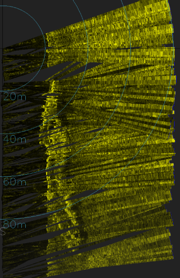
Figure 1. Scan taken in rough water.
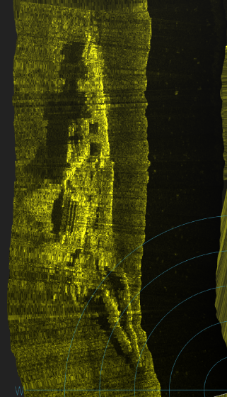
Figure 2. Scan taken during calmer conditions.
Survey Speed
- Survey speeds should be kept within the 0.6 to 1.5 m/s range. A survey speed of about 1 meter per second is a good starting point for most missions. The speed can be lowered to collect high-resolution data, with 0.6 m/s being the slowest recommended speed. Large survey areas can be scanned quickly using a faster survey speed, up to 1.5 m/s, at the expense of image resolution.
- You can save time by making use of the speed change waypoints in QGroundControl to have the boat travel faster between survey areas (1.5 to 2 m/s) and then slowing down while conducting the survey (0.6 to 1 m/s).
Adjusting Range and Transect Spacing
- The sonar range is the maximum distance on either side of the boat that is displayed in the sonar image. Transect spacing is the distance between the transects of a survey mission. Both should be adjusted to achieve the desired overlap between transects and good coverage of the survey area.
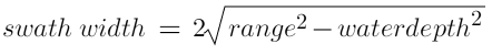
- Remember that the range setting is slant range, not the true horizontal range of the scanned swath. The horizontal width of the scanned swath depends on the range setting and the depth of the water. To get a sense of the swath width for a certain range setting and water depth, you can use the following formula:
Keep in mind this should only be used as a guideline. In real conditions, the actual swath width could be different, and you should plan to have adequate overlap between transects.
- Using a shorter range and closer transects is useful in these scenarios:
- When searching for smaller targets.
- When time and battery life allow for a longer mission.
- If the boat is being sent beyond telemetry range and a live view of the sonar image is not available, a shorter range and smaller transects will increase the chances that a target is located.
- If wind or waves are causing the boat to pitch, reducing the range will increase the ping rate.
- In some environments it’s hard to identify a target from only 1 or 2 passes. Viewing an object from 3 to 4 different perspectives may help interpret the shape better.
- Using a longer range and larger transects is useful in these scenarios:
- In calm water conditions to quickly scan a large area.
- If the target is very large.
- To make a ‘base map’ of an area with the intent to later overlay it with more detailed scans.
- Instead of creating a large survey pattern, it can be helpful to make an initial pass through the middle of the survey area with a long sonar range, 80 to 100 meters, first. This can provide an overall view of the site, and potentially locate a target right away, which allows you to shrink the survey area substantially.
Approach
- It is better to view a target from the side rather than attempt to pass directly over it. When viewed from the side, objects will have stronger reflections relative to the surroundings and will cast an acoustic shadow. There is also more angular resolution when scanning something off to the side.
Replaying Saved Sonar Files
Sonar data is saved as .svlog files in the /userdata/SonarView directory in BlueOS. To replay these files:
1. Enable Pirate Mode in BlueOS then go to the File Browser.
2. Navigate to userdata > SonarView. Select the files you want to view and download them to your computer.
3. Open the SonarView application or extension, and click on Replay Log File.
4. Click on OPEN LOCAL FILE and navigate to the downloaded .svlog files or drag and drop the files into the window.
5. Click on PLAY to begin playing back the sonar data.
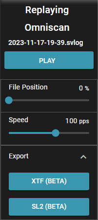
Use the File Position slider to scrub through the sonar data file. Use the Speed slider to increase or decrease the playback speed.
Exporting Files
SonarView can also export the saved sonar files as XTF or SL2 files for use in other applications.
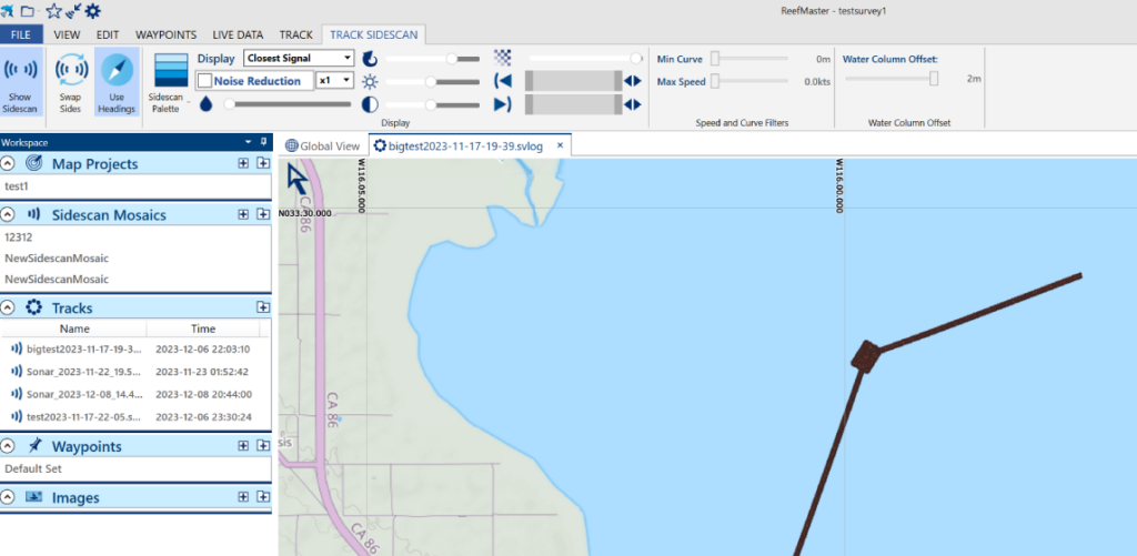
Sonar log file opened in ReefMaster
Open the files as described above. Expand the Export menu and select the desired file type.
Feedback
We’re always working to make our documentation, instructions, software, and user experience even better. If you have any ideas on how we can improve this guide, feel free to let us know here.