
Using a BlueBoat with a Lowrance Sonar for Hydrographic Survey
By Tony White
Introduction
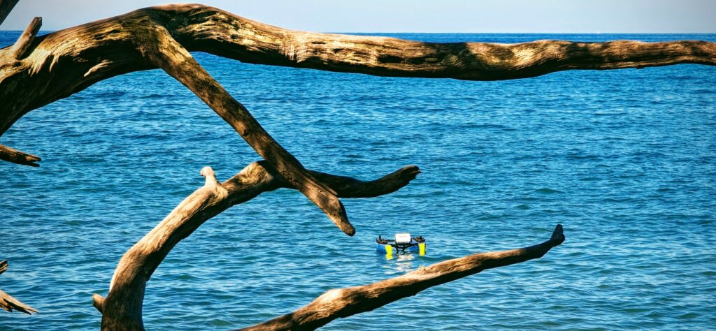
This guide details what may be the easiest way to start making maps with the BlueBoat, with no software knowledge required! A common sight at most harbors are fishing boats with many types of chart-plotters / fish finders. One popular & easy to find choice is the Lowrance Elite FS7, which uses a transducer with three different sonar modes. You can collect accurate depth data with minimal hassle using this system, although you won’t have real-time feedback of the measured depth without additional hardware. Unlike similar units from other vendors, the Lowrance provides a way for a user to easily export and use data. Besides some mounting bolts, you’ll only need a single wet-link penetrator to integrate the system with the BlueBoat. This product only works with surface vehicle applications because you can’t submerge the chart plotter!
Hardware Installation
Parts and Tools
You will need:
- Lowrance Elite FS7 with Active Imaging 3-in1 Transducer ~$900
- 2x M5 by 50mm or ¼”-20 by 2” (used to mount Display)
- 6x M5 or 1/4″ washers
- 2x M5 or ¼”-20 nylon locknut
- #2 Phillips head screwdriver
- Appropriate adjustable-wrench or socket tool for nuts
- Drill with 5.5mm or 1/4″ diameter drill bit
- Penetrator wrench
- MicroSD Card, 64 to 128Gb capacity
- Zip ties for cable management
Mounting the Multifunction Display
Required Materials- Drill with bit
- #2 Phillips head screwdriver
- Appropriate adjustable-wrench or socket tool for nuts
- 2x M5 by 50mm or ¼”-20 by 2”
- 4x M5 or 1/4″ washers
- 2x M5 or ¼”-20 nylon locknut
- 5.5mm LC Wetlink Penetrator
- Lowrance Display Power cable
First, mount the display unit to the rear cross bar, above the cross-tube. With the vessel pointed away from you, and the display facing you, align the left mounting hole of the plastic display mount with the 8th hole to the right of the locking handle.
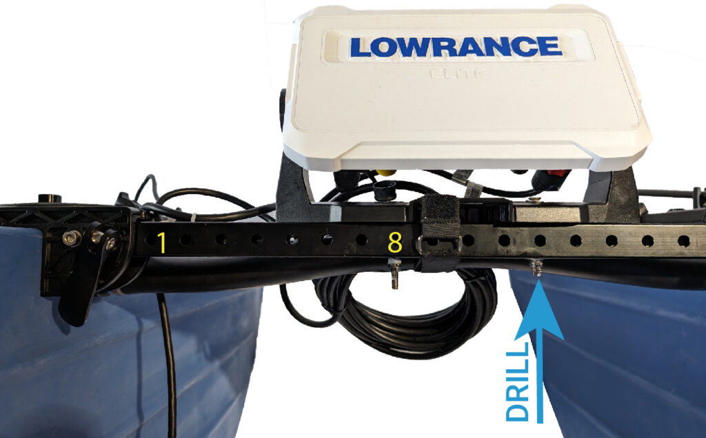
This positioning secures the unit slightly to the right of the boat center-line, offsetting the weight of the transducer on the left. After you secure the left mounting hole with a single M5 by 50mm or ¼”-20 by 2″, remove the display from the bracket and drill an appropriately sized hole up through the crossbar and through the plastic mount, 4 holes over from the existing hole used. Use washers on both ends, between the bolt head/nut and clamped surface, to secure the display with a second bolt of the same size.
Strip the outer jacket from ~300mm/12″ of cable at the end opposite the red Display connector. Make sure you have sufficient cable for the distance from the connector on the Display to the penetrators on the port hull. Cut the cable shorter before stripping if you’d like, but ensure the length your stripping is not required to reach from the display to the hull. Once you’ve verified the length, pass the conductors, colored red & black, through the 5.5mm LC Wetlink penetrator, and secure. Our Wetlink assembly guide has more information on this procedure.
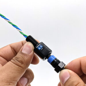
WetLink Penetrator Assembly and Installation
Mounting the Transducer
Required Materials- 2x M5 by 25mm or #10 by 1”
- 2x M5 or 1/4″ washers
- 2x M5 or #10 nylon locknut
- 2x BlueBoat hull mount bushings (included with Payload Bracket)
- Lowrance 3-in-1 Transducer mounted to 90 degree bracket
- #2 Phillips head screwdriver
- Appropriate adjustable-wrench or socket tool for nuts
- Zip ties for cable management
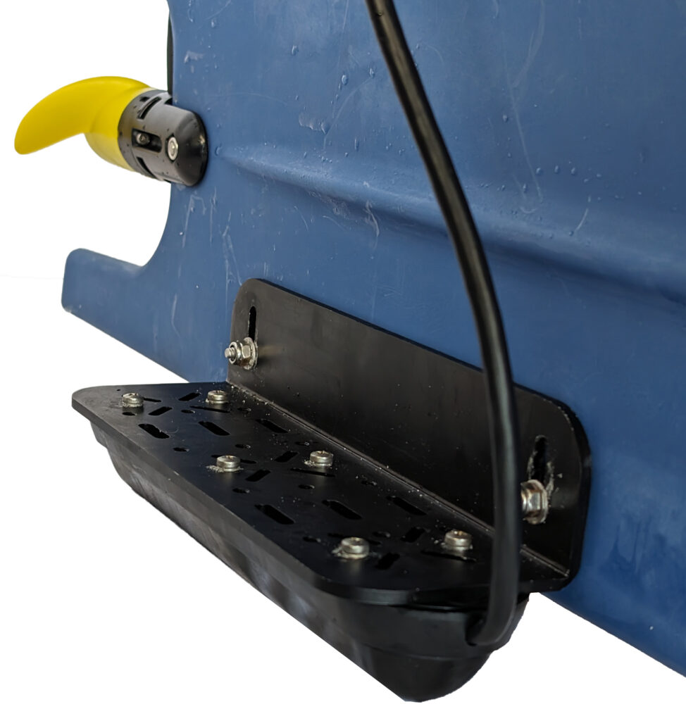
First mount the transducer to the mounting bracket with the included hardware. Next, secure the transducer to the hull mounting holes, below the waterline. Place the bracket so that the transducer is directly below the keel, in the forward-most position on the hull, with the transducer directly below the keel. Each of the bolts included with the 90 degree bracket should go through the hull mount bushing, through the hull, then through the bracket and finally through the metal washer and nylon locknut on the outside surface, as pictured below. Secure the transducer so that it is level with the deck surface by first tightening one bolt completely and holding the angle to the desired position when tightening the second. Try and avoid resting the weight of the boat on the transducer after it’s mounted!
Keep the transducer cable coiled tightly, freeing only enough length to route a small distance aft and to the Display. Use zip ties and/or the velcro cross-tube strap to secure this coil, going around both the Display mount and cross-bar for extra security. Plug the cable into its black colored connector on the right side when you face the back of the display. Secure it with a finger-tightened locking nut.
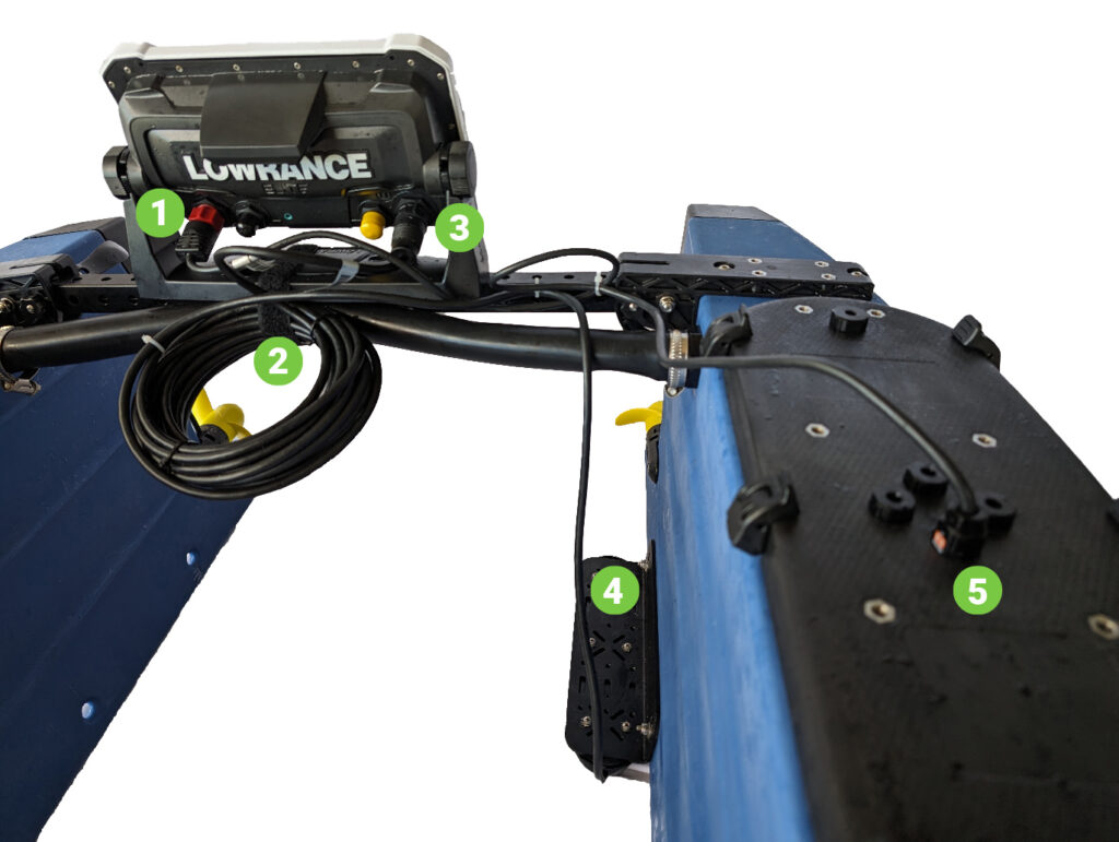
| # | Component |
|---|---|
| 1 | Power Connector |
| 2 | Velcro Strap & Transducer cable |
| 3 | Transducer Connector |
| 4 | Transducer |
| 5 | WLP for Power Connection |
Connecting to power
Required Materials- #2 Phillips head screwdriver
- Lowrance 3-in-1 Transducer mounted to 90 degree bracket
- Penetrator wrench
- Zip ties for cable management
- MicroSD Card
The Lowrance system operates completely independently of both BlueBoat & its telemetry system. Therefore, you only need to connect power from BlueBoat to the Lowrance. While both hulls have available power connection points at the fuse board, we recommend using the port hull to connect the system. This is because the starboard side hosts Navigator and its sensitive IMU electronics.
Remove a blanking penetrator bolt on the port hull and replace it with the WetLink penetrator with power cable installed. Tighten securely with Penetrator wrench.
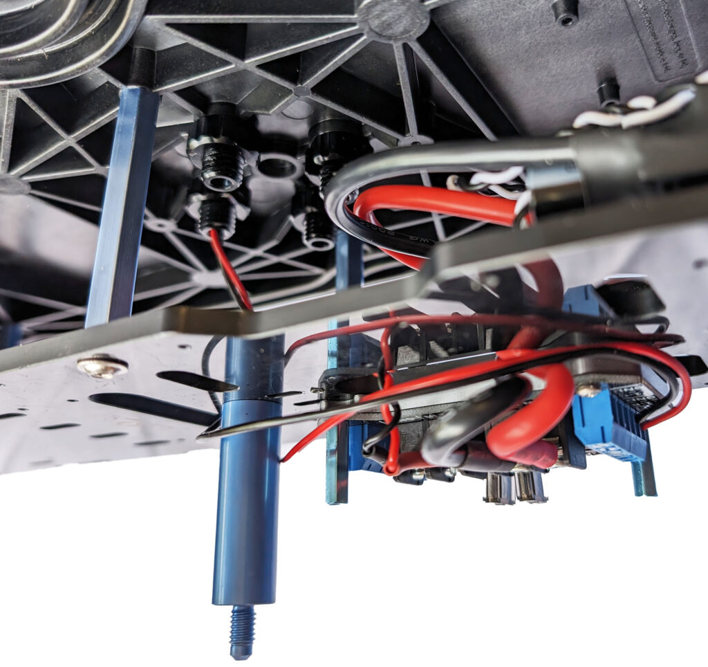
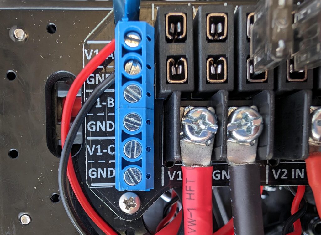
Connect the red and black wires at the fuse board using the included 2A fuse. The terminals labeled V1 supply battery voltage, the terminals labeled V2 supply 5v DC. Once connected, route cable and constrain the wires within the lid before attaching the hatch lid clamshell and closing up the hull. Finish by plugging the power cable into the red connector on the left side of the back of Display.
Testing the Lowrance
Once you’ve finished connecting the power and transducer to the Display, it’s time to power up the BlueBoat. Once you’ve turned on the Boat main power switch, Hold the Display power button in the lower right until the screen lights up and the unit boots. For complete setup details, refer to your Lowrance user manual.
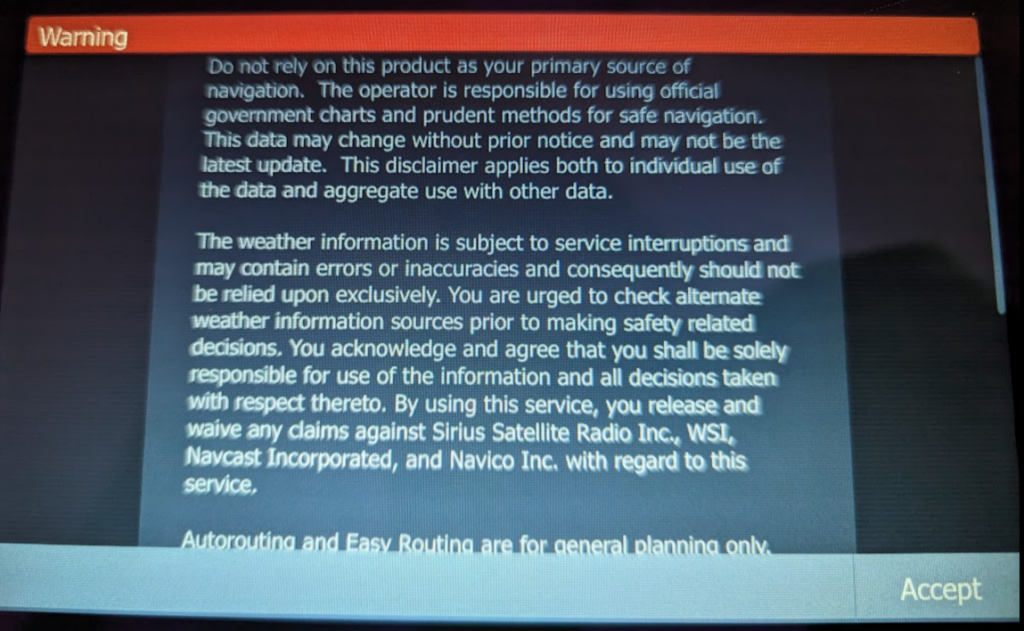
Install the SD card to ensure you have enough storage for large sonar datasets—about 2–4 GB per hour. You must acknowledge the usage terms for the unit every time you power it up.
Field Use
When you’re ready to deploy in the field, follow the normal setup and connection process—refer to the BlueBoat Operator’s Guide. Before you navigate the vehicle away, you must manually power on the Lowrance and activate each sonar—the steps are detailed below.
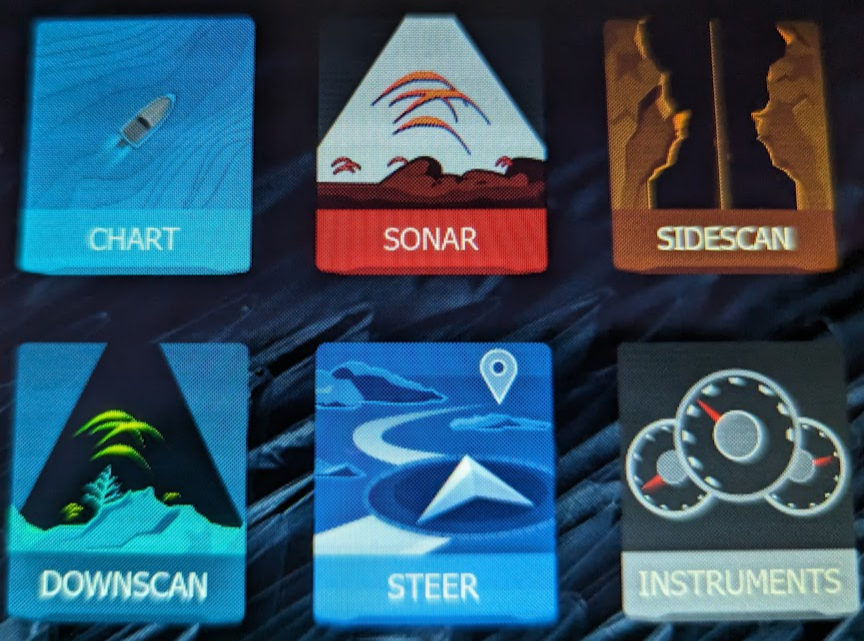
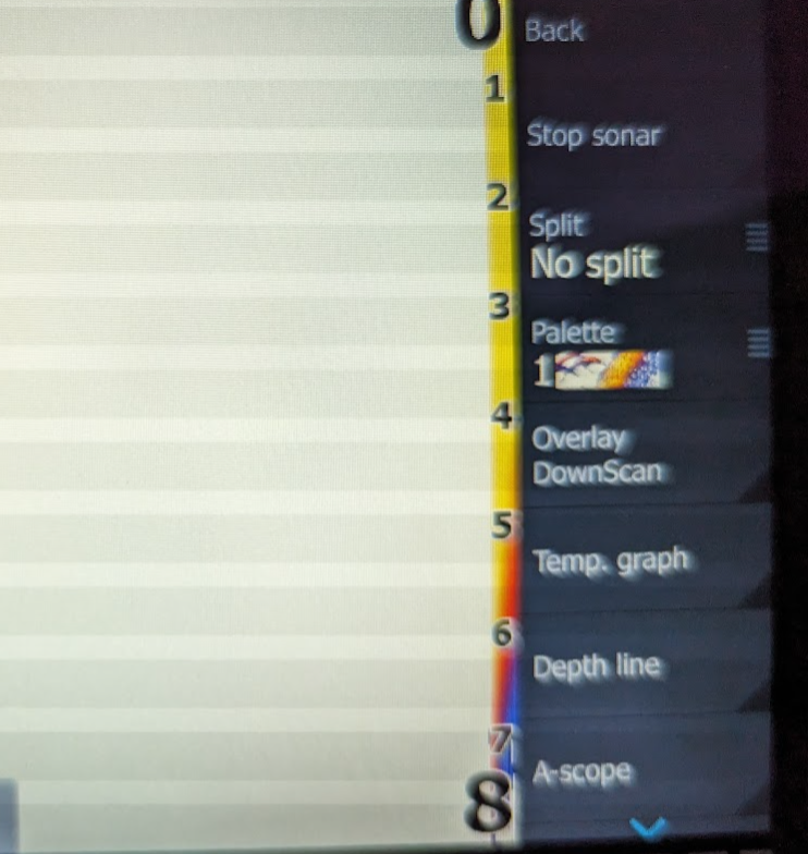
- After accepting the start-up warning, push the pages button in the upper right, and select sonar, sidescan or downscan . The order is not important, just that is each is checked and turned on if not already active.
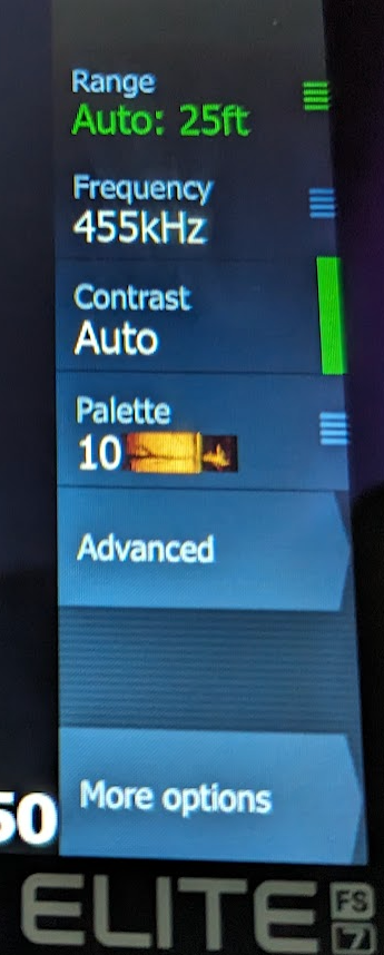
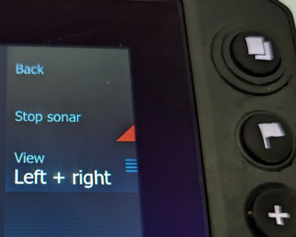
- On the right, select More options and touch the Stop sonar button so the red triangle disappears. At this point, some data may start to show on the waterfall graph.
- This process is repeated for each of the sonars accessed on the main page, but since the Sonar and DownScan turn on & off together, you will only need to toggle one. It is good to check both are collecting data before continuing!
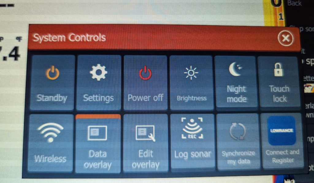
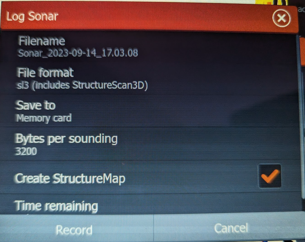
- Now that the sonar is active, push the power button to access the System Controls menu. Select Log Sonar there, and then choose Record to start collecting data.
- Press the power button briefly and repeatedly to lower the display’s brightness to the minimum, then place the cover over the display. This helps save power for the important aspects of operation, and can help prevent overheating the display.
You can now navigate the BlueBoat away from the launch point and conduct the planned survey. For more information on survey planning operations, refer to the Mission planning section of the BlueBoat Operator’s Guide. The Lowrance FS7 consumes about 10 watts of power with all sonars active, so it shouldn’t have a dramatic impact on your battery life.
Stopping data collection
When you’re done with the mission, navigate the vehicle to the best recovery location.
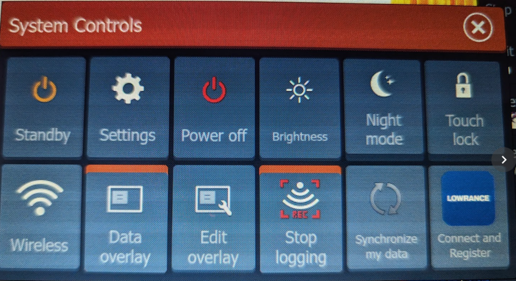
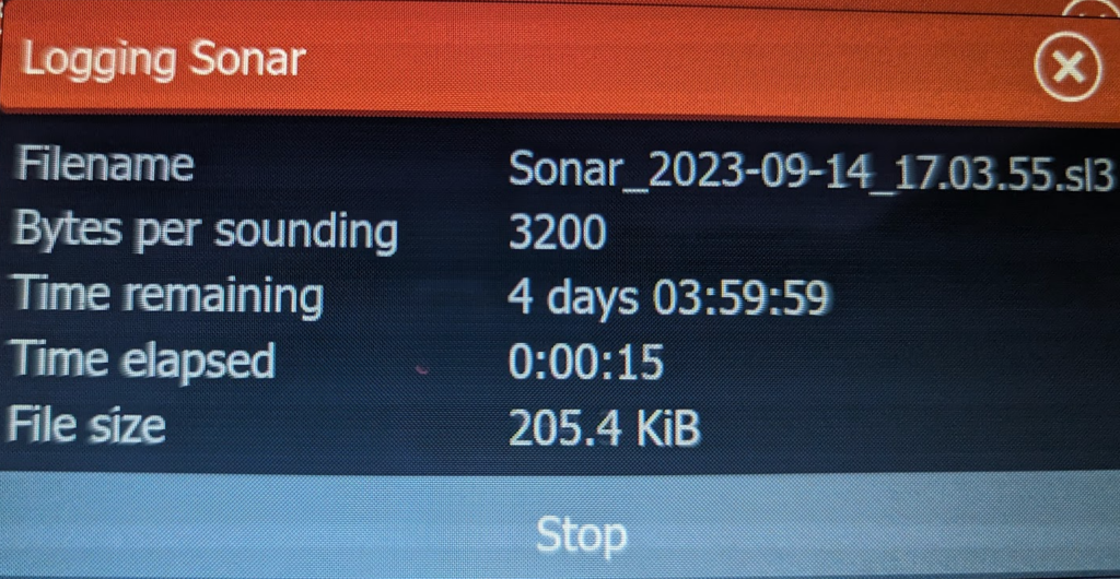
Recover the vehicle and push the Lowrance power button once to bring up the System Controls menu. You can then stop the sonar recording by selecting the Stop logging icon, then selecting Stop. The Blue Boat can then be powered off with the main power switch. Don’t forget to rinse the system with fresh water!
Using the data
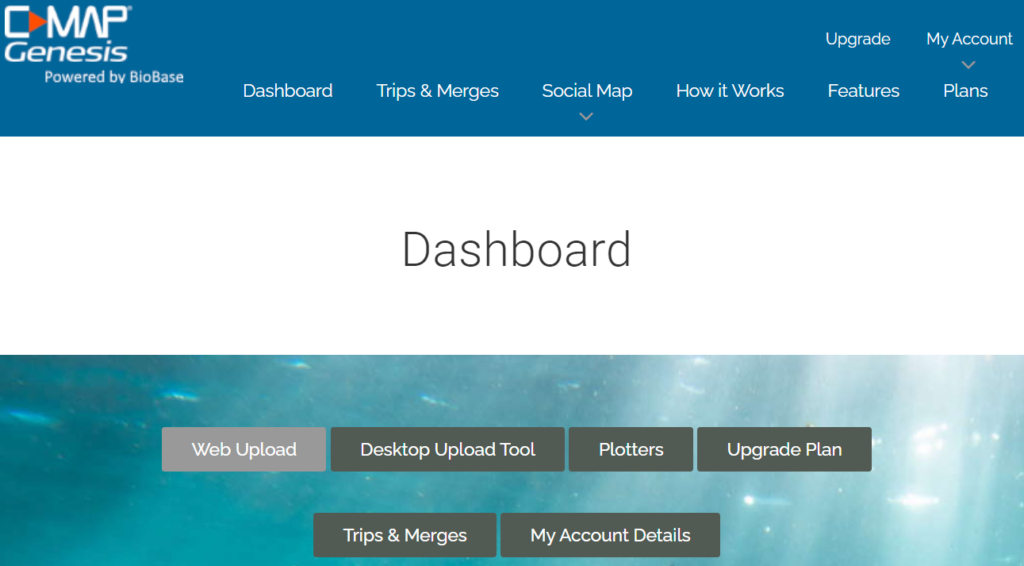
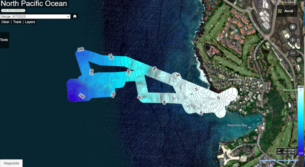
For easiest access to the sonar log data, take out the SD card and copy the files directly to your computer. You could access the Lowrance over its WiFi connection, but this method tends to be finicky, requires Internet Explorer, and is slower, so we won’t detail it here. After you have the data, upload the .sl3 file to C-Map Genesis.

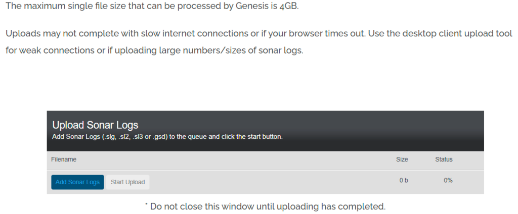
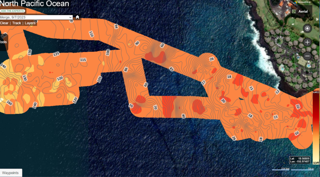
This service offers a free option that makes your data public. However, if you want to keep your data private and generate vegetation and bottom hardness map layers, you can opt for a Premium account, which costs $100/year or $25/month. After creating an account, choose the Web Upload option and upload your .sl3 file.
The Trips & Merges page is where your data ‘surfaces’ after its deep dive into processing! Until it comes up for air, the only indication your data is processing is given in yellow at the upper right of this page.

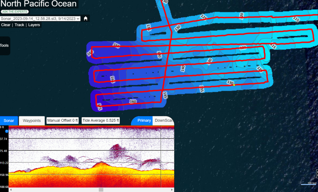
Multiple survey log files across overlapping areas can be combined via “Genesis Merge”, after the data has been processed into standalone maps. When viewing individual trips, the complete primary and down-scan sonar wave forms are available to review, with relative position shown on the map!
Conclusion
This guide covers the basics of using the BlueBoat for survey with common hardware, but there’s lots of room for improvement! Deploying a Ping2 alongside the Lowrance would provides real-time data that guides an operator’s survey. Using a custom tow-fish to haul the sonar transducer behind the boat could broaden the acceptable range of environmental conditions for collecting quality data. Other Sonar systems might offer superior export or additional features, this guide should prove useful for installing any similar solution from a mechanical and electrical standpoint. If you undertake any sort of comparable project, make sure to share your results on our forums!
We’re always working to make our documentation, instructions, software, and user experience even better. If you have any ideas on how we can improve this guide, feel free to let us know here.
Authors

Tony White
Tony White earned his Mechanical Engineering degree from Georgia Tech in 2012 and began his career with large autonomous hydrographic survey vessels with C&C Technologies (Louisiana) and ASV Ltd. (England). He later moved to Los Angeles to join Ocean Lab, where he helped design and deploy a swarm of 50 marine surface drones—the “Data Diver”—his first major project using Blue Robotics components. After some aquaculture experience in Los Angeles, he went on to Forever Oceans in Hawaii (and Panama), where he developed innovative camera monitoring systems and resident BlueROV2 platforms for remote fish mortality extraction. Since 2023, Tony works in Blue Robotics’ Product Experience and R&D departments, where he assists customers with applications and tests both in-house and third-party products, the latter evaluated for potential resale on the Blue Robotics “Reef.”