
A Smooth Operator’s Guide to Underwater Sonars and Acoustic Devices
By Rusty, Nicolette, and Megan
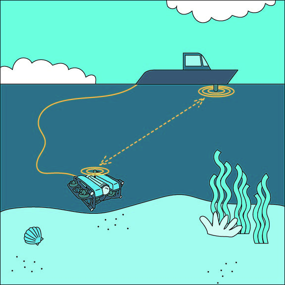
Sonar is one of the most important technologies for the exploration and understanding of the ocean and marine environments. It’s not just one thing though – it’s an entire category of devices used for different applications. This article is the perfect place for beginners and sensitive hearts, and provides an overview of some of the most common types of sonar used in marine robotics, especially on ROVs, UUVs, and USVs.
We’ll hit on some of the most common categories of sonar devices, including echosounder sonars, imaging sonars, and acoustic positioning/velocity sonars.
Let’s dive in to learn more!
Echosounders
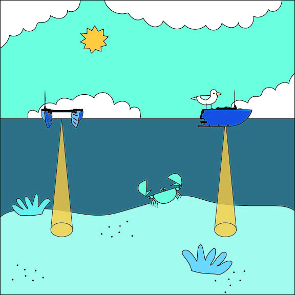
Echosounders are used for “bathymetry,” which is the measurement of water depth in oceans, seas, or lakes. Bathymetric surveys are done by hydrographers, working to understand the physical properties of the ocean and other bodies of water. To do that they use echosounder sonars and there are two common types: single beam echosounders and multibeam echosounders.
Single Beam Echosounder
A single beam echosounder (SBES) uses sound waves to measure distance in water. It is one of the most fundamental types of sonar and is used on nearly every boat in the world to measure water depth to avoid running aground. It’s also the type of sonar used in a “fish finder” sonar. In the hydrographic world, it’s one of the most common and cost-effective tools for bathymetric surveys. In ROV and UUV applications, echosounders are used for measuring the altitude over the seafloor and for obstacle avoidance.
In a single beam echosounder, an acoustic transducer emits a sound wave, which travels through the water and then bounces back when it encounters the seafloor or other objects in the water column. The transducer then receives the reflected sound wave, and measures the time it took for the sound wave to return. Using a known speed-of-sound in water, it can then calculate the distance to the seafloor. It’s important to note that the accuracy of all sonars, including echosounders, can be affected by factors such as water temperature, salinity, and sound velocity variations.
Ping Viewer interface being used to view and record Ping2 Sonar Altimeter and Echosounder data
Echosounders are often offered in a “dual frequency” configuration, which allows the sonar to operate at two different frequencies. Low frequencies tend to have longer range, wider beamwidth, and lower resolution, while high frequencies tend to have shorter range, narrower beamwidth, and higher resolution. A dual frequency sonar will be capable in a broader range of operating conditions.
Single beam echosounder beam shape
Single beam echosounders provide a single depth measurement point directly below the transducer, creating a depth profile along the path of the vessel when doing a survey. That provides enough detail to create a rough map of the depth, but not enough to show fine details like seafloor topography, bathymetric features, or underwater objects.
Despite these limitations, single beam echosounders are still widely used in many applications where their simplicity, cost-effectiveness, and ease of use are advantageous. However, if you’re looking for more detail and resolution in your mapping, then you may need a multibeam echosounder.
Single Beam Echosounder Highlights
| Pros | Cons |
|---|---|
| Cost effective (starting at a few hundred dollars) | Low detail when mapping |
| Compact size | |
| Simple operation and data |
Multibeam Echosounder
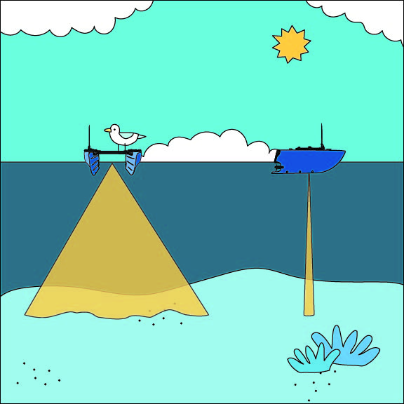
Multibeam echosounders (MBES) also measure water depth, but at many points at once, providing much more detail and the ability to see the shape of the seafloor and detect objects. When you hear stats about how much of the ocean has been mapped, like, “less than 30% of the ocean has been mapped,” they’re talking about detailed maps made with multibeam echosounders. Multibeam echosounders are the gold standard for bathymetry in most applications, but that comes at a much higher cost and level of complexity.
Multibeam echosounder beam shape
A multibeam echosounder works by emitting a single sound wave from a transducer that’s mounted to the hull of the vessel and then listening back for returns on many smaller transducers. By doing some math, it’s able to determine exactly what direction each part of the returned sound wave came from, letting you see “multiple beams” instead of just a single beam. With that, you can create a detailed bathymetric map quickly and efficiently.
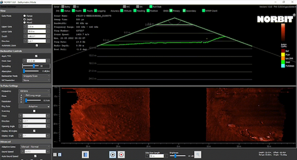
Interface for Norbit multibeam sonar
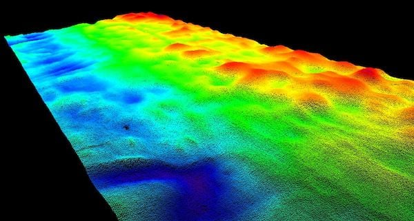
Processed data for Norbit multibeam echosounder
Multibeam echosounders are an important tool for understanding and mapping the world’s oceans and underwater environments. The high-resolution bathymetric data provided by a multibeam echosounder shows details such as trenches, ridges, valleys, and seamounts. They are often used in hydrographic surveying, oceanographic research, marine resource exploration, underwater mapping, and navigation for ships and submarines.
They do come with some drawbacks including that they are usually expensive, bulky, and heavy. The large amount of data generated by multibeam echosounders can also be complex to process and interpret – advanced data processing skills and software are often required to extract meaningful information from the raw data. Multibeam echosounders can also be susceptible to interference from objects or organisms in the water column, such as fish, bubbles, or suspended particles, which can result in noisy or distorted data that may require additional processing or filtering to obtain accurate results.
Multibeam Echosounder Highlights
| Pros | Cons |
|---|---|
| Capable of high resolution seafloor mapping | Can be expensive (starting at $5,000+, but most $30,000+) |
| Measures a large area at once | Often large and heavy |
| Complex data processing required | |
Imaging Sonars
Another category of sonar is imaging sonar, which allows you to collect sonar images of the seafloor and underwater features to find objects and aid in underwater vehicle navigation. The most common types of imaging sonars are scanning imaging sonars, multibeam imaging sonars, and side scan sonars.
Scanning imaging and multibeam imaging sonars are the most common types used on ROVs. They are used in low visibility water conditions as a navigational aid, giving the pilot a sense of their location by showing nearby objects, structures, and seafloor details. They can also be used for object detection, such as finding a shipwreck on the seafloor from a distance.
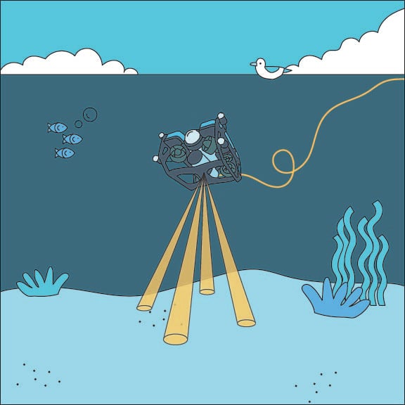
Scanning Imaging Sonar
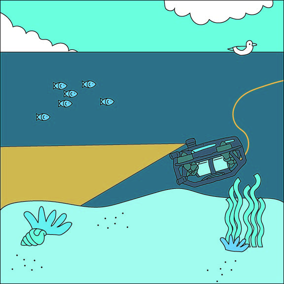
A scanning sonar is similar to a single beam echosounder, but it’s constructed with a specialized fan-shaped acoustic beam and a motor that rotates the sonar transducer for 360 degree coverage. You can imagine the beam like a flashlight shining in a dark area, revealing a thin slice of the environment at a time. As the sonar transducer is rotated, it collects data and builds up a complete 360 degree image.
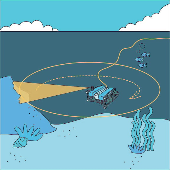
Scanning imaging sonar beam shape
Scanning sonars are well suited for applications that require detailed, high-resolution imaging of specific areas or objects underwater like underwater inspection and maintenance, underwater mapping and surveying, and fisheries and marine biology.
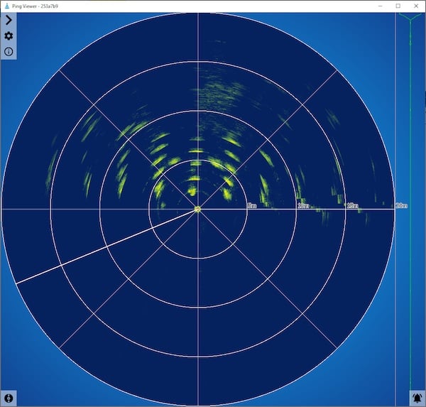
PingViewer displaying dock pilings straight ahead of BlueROV2 using Ping360 Scanning Imaging Sonar
However, the scanning speed of a scanning sonar is relatively low, taking 5-20 seconds to complete a 360 degree scan, which can make it difficult to use in dynamic environments with lots of movement. In ROV applications, it’s common to set the sonar to scan just one limited sector of interest to increase the scanning speed.
Side view of scanning sonar beam
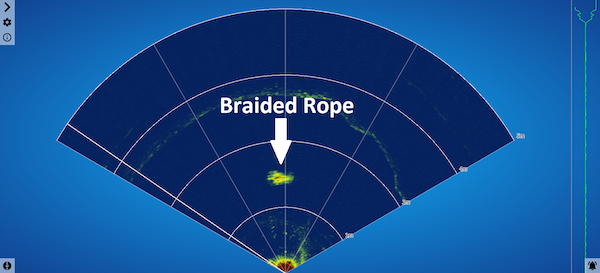
A 120 degree sector scan showing a rope in front of the Ping360 Scanning Imaging Sonar
Scanning Imaging Sonar Highlights
| Pros | Cons |
|---|---|
| Cost effective (starting around $2,500) | Slow scanning speed (5-20 seconds for 360 degrees depending on range) |
| High resolution and detail | |
| 360 degree coverage |
Multibeam Imaging Sonar
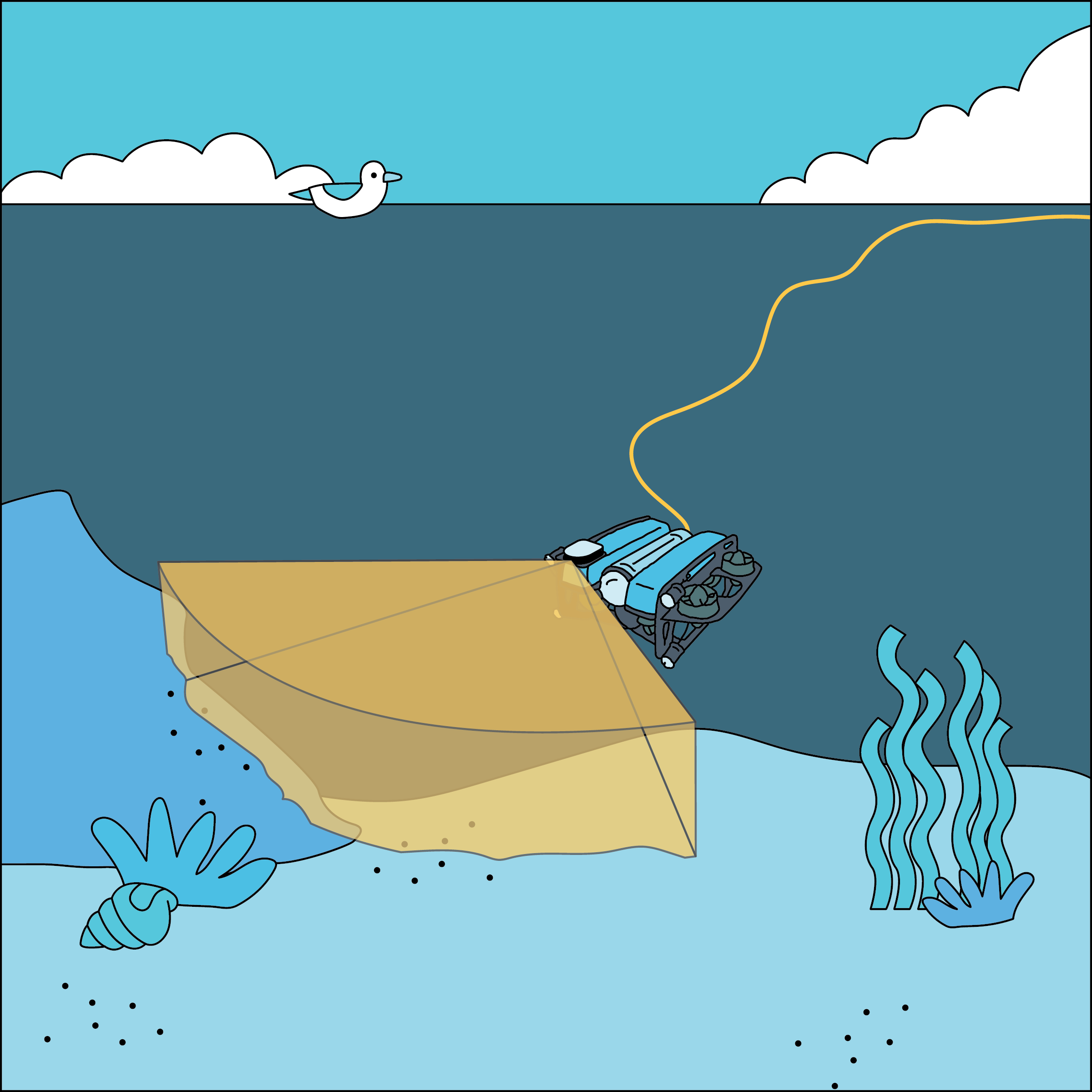
Multibeam imaging sonars are used for similar applications as scanning sonars, but are technologically very different. These sonars are sometimes referred to as “forward looking sonars” because they have an overall view that’s only about 90 degrees wide and typically pointed forwards from the vehicle. The biggest advantage of multibeam imaging versus scanning imaging is that a multibeam sonar has a much faster update rate. It’s able to update the image multiple times per second.
Like a scanning sonar, the multibeam imaging sonar gives you a view of structures, objects, and the seafloor around you, making it a good navigational aid. Since the image updates quickly, it’s easier to identify particular objects, making multibeam sonars popular for search and rescue applications. They’re also well-suited to underwater inspection and can provide accurate dimensional information on structures or other objects.
Multibeam imaging sonar beam shape
Multibeam imaging sonars operate with the same principle as a multibeam echosounder: a single transducer emits a sound pulse and the returning echoes are received by an array of smaller transducers. The size of this array is correlated with the angular resolution of the device and most sonars have 64 to 256 individual receive transducers. The received data is processed to calculate the strength of the response for each beam, producing an entire image every time it collects data.
Note, an underwater multibeam imaging sonar is very similar to a medical ultrasound machine used to image growing babies and medical conditions! They’re optimized for performance in a different operating environment, but the concept is the same.
The difference between a multibeam imaging sonar and multibeam echosounder is the beam shape. Imaging sonars have a wedge shaped beam that allows you to see the seafloor when pointed straight forward. In contrast, echosounders have a narrow line-shaped beam that is better for detailed measurements of the seafloor.
The resulting image from a multibeam imaging sonar is shaped like a pie slice and shows everything in front of the vehicle, with the furthest objects being at the wide end of the pie slice. The image is updated in real time as the vehicle moves around or as objects, like fish, move in the view.
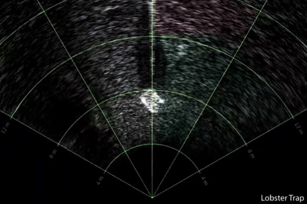
Lobster trap being viewed on Sonoptix Echo, a low-cost, forward-looking, multibeam sonar system
Multibeam imaging sonar is typically the preferred option for ROV pilots, but it does have some drawbacks including high cost, limited distance range, and a narrow view angle. Multibeam imaging sonars are typically several times more expensive than mechanical scanning imaging sonars. Their range is generally effective at ranges up to 200 meters, but beyond that, the quality and resolution of the images can degrade.
Multibeam Imaging Sonar Highlights
| Pros | Cons |
|---|---|
| Fast scan speed (5+ times per second) | Expensive (starting at $9,000) |
| High resolution and detail | Smaller coverage angle around 90 degrees |
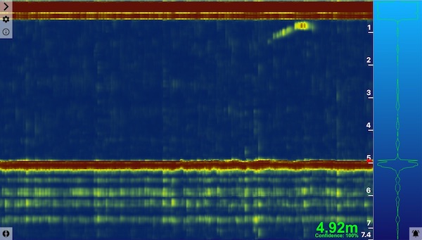
Side Scan Sonar
Side scan sonar is commonly used to survey large areas of the seafloor. It emits fan-shaped pulses and then listens for the echo response through a transducer that is either mounted to a boat’s hull or towed behind a boat (called a “towfish”). Those pulses are recorded to create slices of an image that are then stitched together. Side scan sonar offers a wide beam, so it allows you to cover large areas in a short period of time. It is a go-to for object detection and is used on boats, towfish, and UUVs more than ROVs as it tends to need to travel in long straight lines.
Side scan sonar beam shape
Side scan sonar is used when you want to image large areas of the seafloor quickly, making it popular for mapping, search and recovery, underwater archaeology, shipwreck hunting, and environmental monitoring. It can provide detailed information about the shape and texture of the seafloor, and can be used to identify submerged objects such as sunken ships, debris, or geological features. Side scan sonar data is typically displayed in grayscale or color images, known as side scan sonograms, which provide a visual representation of the underwater environment.
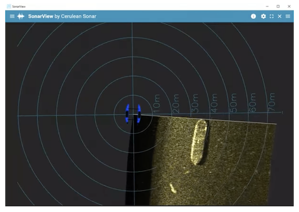
SonarView interface showing conventional side scan view using Cerulean Omniscan 450 Side Scan Sonar
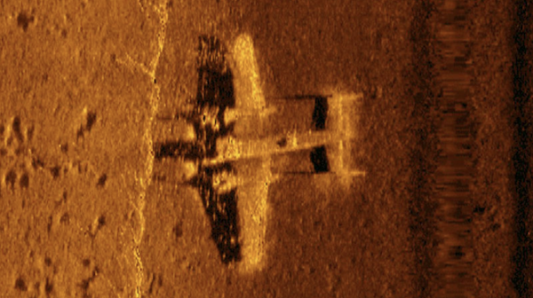
Example of processed data from a side scan sonar of a WWII B-25 discovered in 2017 in Papua New Guinea (image courtesy of Project Recover, NOAA)
The effective range and coverage of side scan sonar can be influenced by factors such as water depth, sonar frequency, and bottom conditions. It’s particularly limited in very shallow water, where the coverage area is quite small, and deep water, where the range is insufficient to see the bottom or have much coverage area. For this reason, side scan sonars are often operated from UUVs that can maintain an optimal depth from the seafloor.
Interpreting side scan sonar data can also be challenging, as the images generated are not always intuitive or easy to interpret, especially for those who are not experienced in interpreting sonar data. Distinguishing between different types of seafloor features, such as rocks, wrecks, or biological structures, can require specialized knowledge and expertise.
Despite these limitations, side scan sonar is a versatile technology with many applications. Its ability to create detailed images of the seafloor and underwater objects has made it an essential tool for researchers, surveyors, and other professionals working in the field.
Side Scan Sonar Highlights
| Pros | Cons |
|---|---|
| Cost effective (starting at a few thousand dollars) | Limited effectiveness in very shallow or deep water |
| Large scanning area | Unintuitive imagery |
| High resolution imaging | |
| Imagery can be georeferenced easily |
Positioning and Navigation Sonar
Another category of sonar is designed to help track the position of subsea vehicles, enabling accurate underwater navigation. For position, there are several types of acoustic positioning systems, all using some form of triangulation to track a transponder. And for velocity, there is a doppler velocity logger, or DVL, which allows a vehicle to track its motion relative to the seafloor.
Acoustic Positioning System
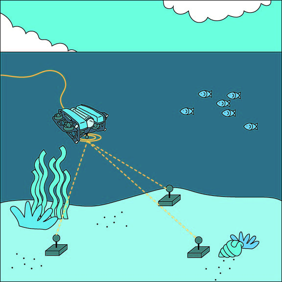
Acoustic positioning systems consist of a transponder that emits a sound pulse, usually attached to a vehicle or other underwater asset, and multiple receivers. The receivers hear the sound pulse at slightly different times, allowing them to triangulate the position of the transponder. There are three flavors of acoustic positioning systems: long baseline (LBL), short baseline (SBL), and ultra short baseline (USBL).
A long baseline system (LBL) is most common in large installations such as underwater construction, pipeline installation, subsea asset inspection, and scientific research sites. It uses a network of transponders on the seafloor, typically mounted in the corners of the operation site, as reference points for navigation. The LBL yields high positioning accuracy and position stability. Their range is typically a few kilometers, but this can vary depending on the system and environmental conditions.
LBL
The second class is a short baseline system (SBL). An SBL system does not require transponders to be mounted to the seafloor, but instead uses a baseline consisting of three or more individual transducers that are connected by wire to a central control box, oftentimes lowered over the side of a surface vessel. The accuracy of an SBL depends on the spacing and mounting method of the transducers, with typical accuracy around 1-3 meters. SBL systems are typically used in applications where longer range positioning is required, such as underwater tracking of large structures like underwater buoys, moorings, or platforms, and for underwater communication systems.
SBL
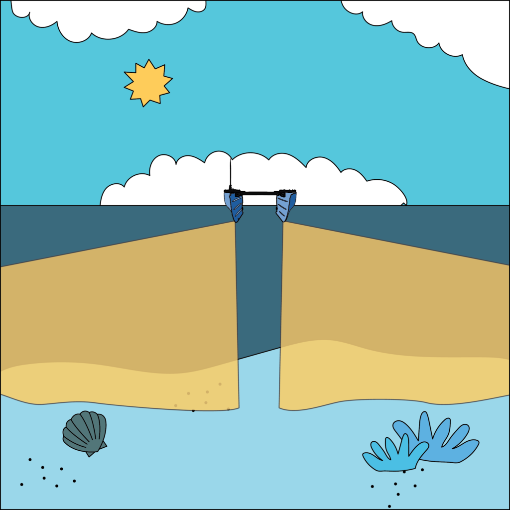
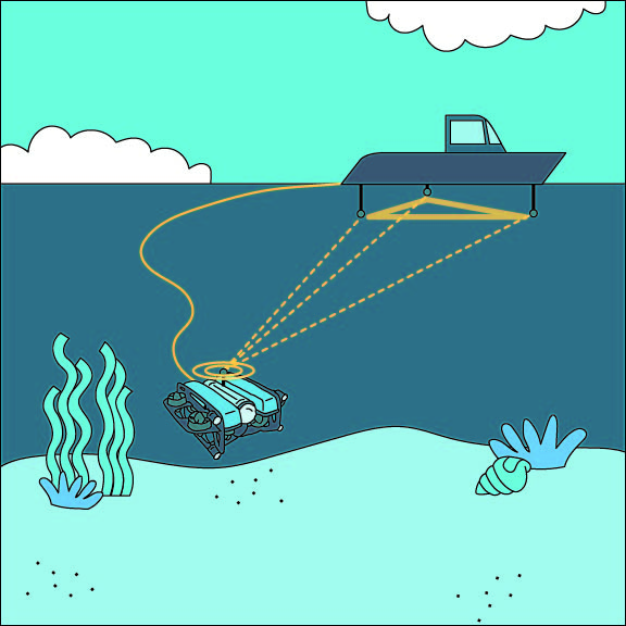
An ultra-short baseline system (USBL) is the third type of underwater acoustic positioning system and consists of two parts – a transceiver, which is mounted on a pole under a ship, and a transponder, which can be on the seafloor, towfish, or ROV. Rather than time-of-flight based measurement, a USBL uses phase shift to determine the angle to the transponder.
USBL systems can provide high-precision positioning with accuracies in the range of a few meters, depending on the system and environmental conditions. The range of USBL systems is typically limited to less than 1,000 meters, and they provide high-precision positioning in real-time.
USBL systems are the most commonly used type of acoustic positioning for ROVs due to the compact size and ease of use.
USBL
Doppler Velocity Logger
A Doppler Velocity Logger, or DVL, is used to measure the velocity of an underwater vehicle relative to the seafloor. The velocity measurements from a DVL are so accurate that they can be integrated over time to provide a precise position estimate as well. A DVL can detect small changes in movement much better than any of the acoustic positioning systems above, with the caveat that it can’t directly measure absolute position, so it needs input from a GPS or acoustic positioning system occasionally to maintain an accurate position estimate.
DVLs leverage the Doppler effect in a clever way to measure velocity. The DVL consists of 3-4 acoustic transducers pointed downwards and angled about 15 degrees. Each transducer emits a pulse, which hits the seafloor and returns to the device. If the vehicle is moving, the frequency of the returned pulse will be slightly different than the frequency that was emitted. By measuring the difference between those frequencies, the velocity can be calculated. With 3-4 transducers each doing this, it’s possible to calculate velocity in three dimensions.
DVL
Relative to a starting point, a DVL can typically track position accurately to +/- 0.1% of the distance traveled. This makes it one of the most important sensors to enable autonomous navigation underwater. DVLs are often used on ROVs and UUVs to provide position information and to enable capabilities such as position holding and waypoint navigation.
There are a few downsides to DVLs. First, as mentioned earlier, they cannot provide a long-term accurate position estimate without the help of a GPS or acoustic positioning system. Additionally, since they track motion relative to the seafloor, they need a clear view of the seafloor and have limited range. For example, on a vehicle with a DVL with 50 meter range, the vehicle must be 50 meters or closer to the seafloor to provide a velocity measurement.
For more info, check out this post on our forums discussing the limitations of DVLs.
There is a community-sourced comparison table of some common DVLs available here.
Other Types of Underwater Sonar and Acoustic Devices
We’ve covered many of the common types of sonar devices here, but don’t worry, there’s more! For the sake of completeness, here’s a list of all the types of devices we know about and a quick description of them.
Acoustic Modems
Since radio waves don’t travel far underwater, acoustic modems are used for most underwater wireless communications. They work on the same principles as wireless radios, but using sound waves rather than radio waves.
Because of the lower frequency of sound waves, acoustic modems are limited in communication speed (think dial-up modem speeds, at best). They typically communicate over distances of 200m to several kilometers.
Acoustic Pingers/Beacons
Sometimes it is only necessary for a device to broadcast an acoustic signal, without receiving responses. Acoustic pingers can be used as locating and identification beacons for a vehicle or important piece of infrastructure, as alarms to indicate some kind of status, or to transmit specific frequencies that deter marine mammals from a hazardous area.
Acoustic Reflectors
As a complement to echosounders, there are passive acoustic devices which strongly reflect sonar pulses. In simplest form these can be flat plates with a significant density difference from the surrounding water, with their size, shape, and orientation tuned to the expected incoming pulses and the desired outgoing ones.
There are also acoustic retro-reflectors, which reflect incoming pulses back towards the transmitter, like cat’s eyes and traffic signs reflecting headlights. These can be useful as locating features in applications where an acoustic pinger is impractical due to power or wildlife disturbance concerns, but require that the searching vessel have an echosounder that can transmit at the appropriate frequency (instead of only needing a receiver for nearby pingers).
As a passive device a reflector’s signal is limited to presence detection, compared to the ID and location signals a pinger could send, or the bi-directional communication that is possible between acoustic modems.
Acoustic Releases
An acoustic release is a device that listens for a specific signal, and then actuates a mechanism to release hardware anchored to the seafloor or deploy a lift bag. They’re common enough that a few companies make them and they may be an important part of future ropeless fishing efforts.
Acoustic Tags
These small transponders are primarily used by marine biologists to tag animals and track their movement. Receivers installed in specific places listen in for pings from the transponders and generate data on location, migration, and behavior.
Hydrophones
The term hydrophone is a very general term, referring to any underwater listening device, but typically refers to an acoustic transducer designed to listen to audible frequency ranges from all directions. They’re used by scientists to listen to marine mammals.
Sound Velocity Probes
In some applications, such as high-end multibeam imaging sonar, an accurate knowledge of the speed of sound is essential. A sound velocity probe (SVP) allows that to be measured directly. An SVP is essentially a tiny echosounder with a fixed reflecting plate and the time-of-flight of the response is used to determine the speed of sound.
Thickness Gauges
An ultrasonic thickness gauge is a common tool both above and below water. It emits an acoustic pulse into an underwater structure, like a beam or boat hull, and uses the response to determine the thickness of that object. That information is used to evaluate corrosion and structural health.
What are we missing?!
If you are aware of a type of underwater acoustic device that we didn’t mention, let us know!
Where to go from here
By now, you should have a basic understanding of the types of underwater sonar and what they are used for. This is no place to be ending but somewhere to start. If you’re interested in learning more, we invite you to dive into our Wave of Sonars & DVLs comparison spreadsheet for a more detailed breakdown of the sonars and DVLs on the market! We also have our own sonar products you can check out:
And don’t miss the The Reef, a curated collection of products from some of the most innovative companies in the industry that will take your marine robotics efforts to the next level!
If you are in the US, looking for funding, and are associated with a non-profit or educational program check out The Sonar Equipment Fund. The Sonar Equipment Fund is helping institutions, researchers, and community partners gain access to professional-grade sonar systems that have traditionally been out of reach.
We encourage you to explore the depths of the internet for more, including this playlist if you are left feeling inspired! If you have any questions, please start a discussion on our community forums, where we and some of the best subsea experts around the globe are eager to chat!
Authors

Rusty
Rusty is the founder and CEO of Blue Robotics. His background is in engineering but he likes to be involved in everything at Blue Robotics!

Nicolette
Nicolette is the Web Content and Systems Manager at Blue Robotics AKA she keeps the website funky fresh.

Megan
Megan is the Creative Collaborator + Graphic Designer human at Blue Robotics, but she does like to dabble in other areas as well :)