
Integrating a Water Linked DVL on the BlueROV2
Introduction
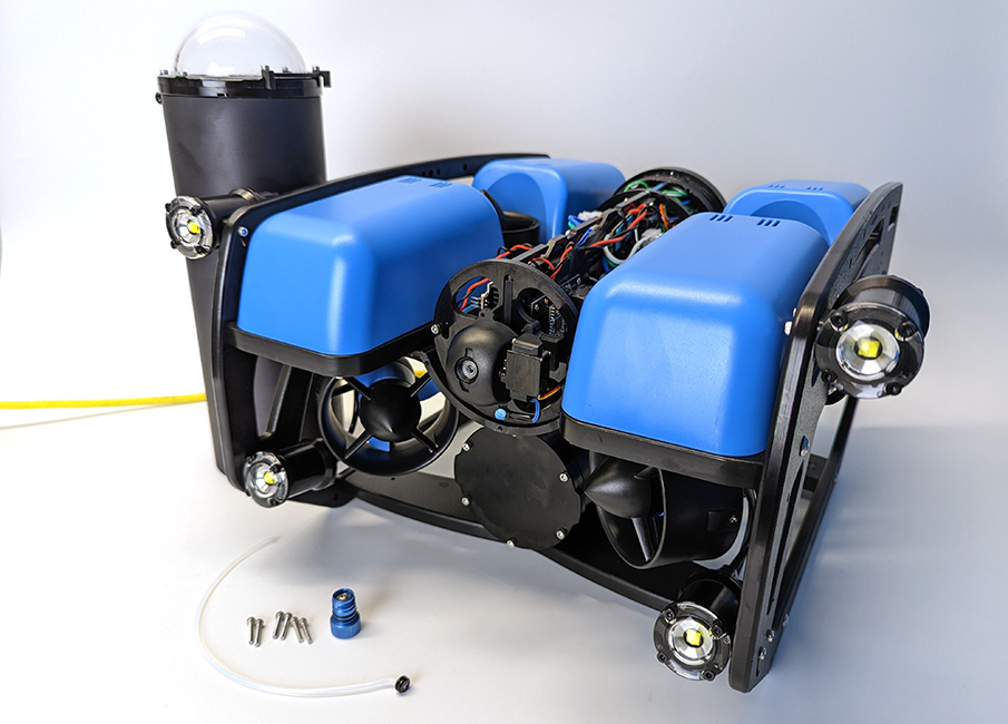
The Water Linked DVL A50 and A125 are the world’s smallest Doppler velocity logs. Together with Water Linked DVL BlueOS extension, they enable position holding and autonomous navigation capabilities on the BlueROV2. When purchased from The Reef by Blue Robotics, The DVLs come preconfigured for easy installation and plug-and-play operation with the BlueROV2. This guide will show you how to install and operate the DVL A50 and A125 with a BlueROV2.
You can also check out Water Link’s complete DVL documentation on their documentation site here.
Hardware Installation
Parts and Tools
You will need:

You will also need:
- 1 x M10 Bulkhead Wrench
- 1 x 2 mm hex driver (for DVL A50 only)
- 1 x 2.5 mm hex driver
- 1 x 3 mm hex driver
- 1 x #2 Phillips screwdriver
- 1 x Power drill and a 5.50 mm (or 7/32″) drill bit (for DVL A50 only)
- Sharpie or other type of marker (for DVL A50 only)
- Silicone grease (Molykote 111)
- Cable ties for cable management
Preparing the BlueROV2
You will have to open up the BlueROV2 Electronics Enclosure and remove one of the penetrators to install the DVL. To do this you will need:
- 1 x 2.5 mm hex driver
- 1 x M10 Bulkhead Wrench
If you are not sure how to perform any of the steps in this section, more detailed instructions for each operation are available in the ‘Servicing the BlueROV2’ section of the BlueROV2 Operation guide.
1. Make sure your BlueROV2 is completely powered off by disconnecting the battery.
2. Use the 2.5 mm hex to remove the M3x16 mounting screws that secure the enclosure mounting clips to the cradles, remove the PRV or vent plug, and remove the Electronics Enclosure tube from the Electronics Enclosure assembly.
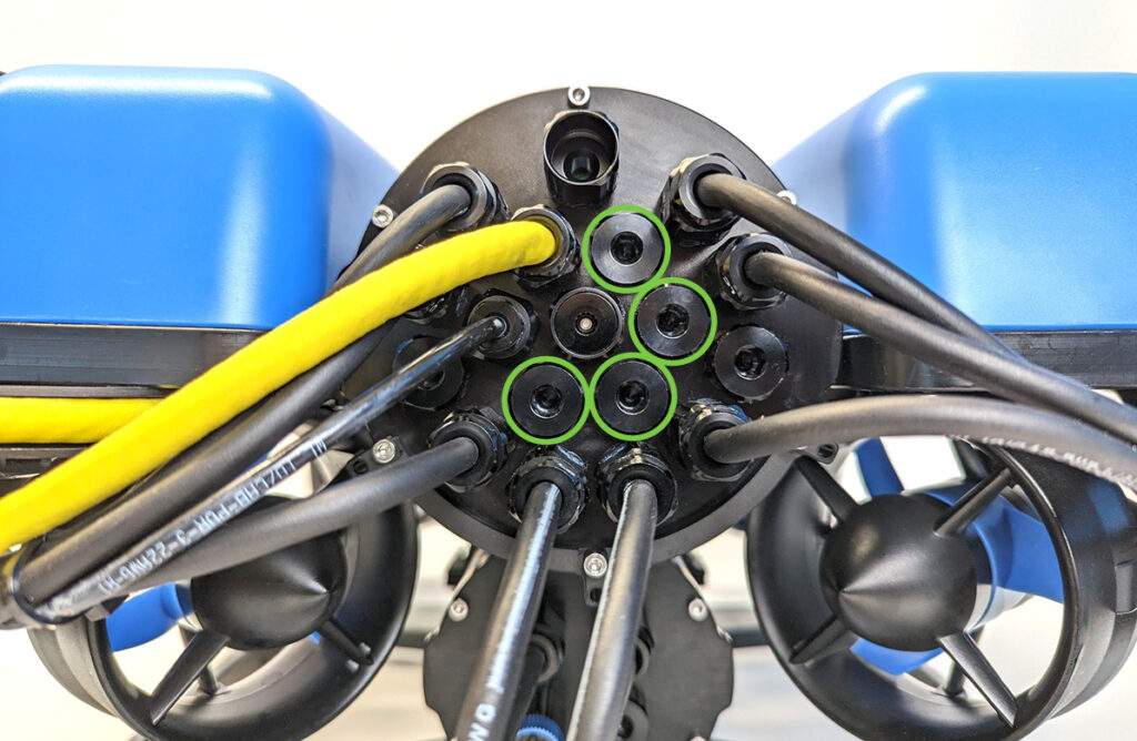
3. Choose one of the blank penetrators in the middle of the end cap and use the M10 Bulkhead Wrench to remove it.
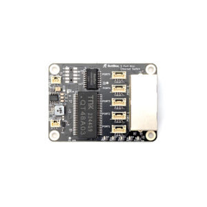
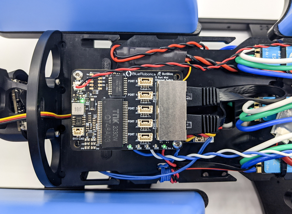
4. Install the Blue Robotics Ethernet Switch if you have not done so already. Follow the Ethernet Switch installation guide to install the Ethernet Switch in your ROV. Come back to this guide when you are done.
Installing the Penetrator
To install DVL’s penetrator into the end cap, you will need the following parts and tools:
- 1 x DVL
- 1 x Penetrator Nut (included with the DVL)
- 1 x Penetrator O-ring (included with the DVL)
- 1 x Silicone Grease (Molykote 111)
- 1 x M10 Bulkhead Wrench
1. Wipe the exterior surface of the end cap around the penetrator hole you previously removed the blank penetrator from. Ensure the area around the hole where the O-ring will sit is free of dust or debris.
2. Inspect the penetrator O-ring to make sure it is not dirty or damaged.
3. Lubricate the O-ring with a thin layer of silicone grease and install it in the groove on the underside of the penetrator.
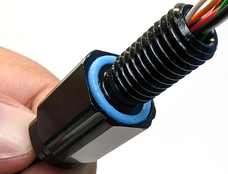
4. Install the penetrator in the hole and fasten the penetrator nut on the other side. Tighten the nut and bulkhead by hand until finger-tight. Use the Bulkhead Wrench to fully tighten the penetrator. The penetrator should no longer rotate in the hole and you should not be able to loosen it using your fingers when installed properly.
Wire Connections and Reassembly
To connect the wires inside the ROV you will need:
- 1 x #2 Phillips head screwdriver
- 1 x 2.5 mm hex driver
- The M3 mounting screws you removed previously
- Silicone grease (Molykote 111)
1. Use the #2 Phillips head screwdriver to connect the spade connectors at the end of the power wires to available screw terminals on the power terminal blocks. Connect the black power wire to the terminal block with the other black wires and connect the red power wire to the terminal block with the other red wires.
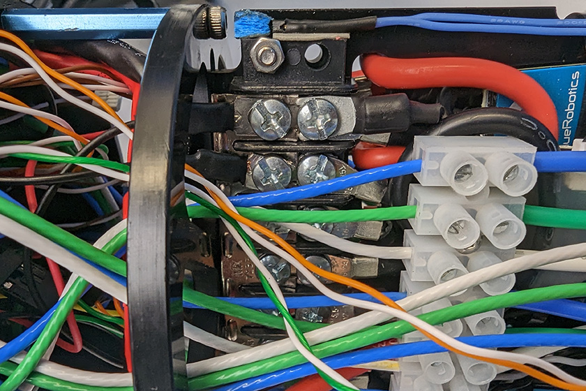
All the black power wires.
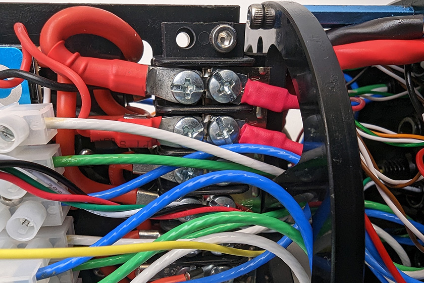
All the red power wires.
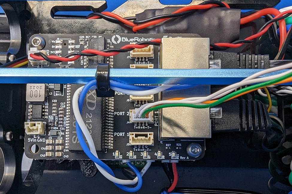
2. Connect the 4-position JST GH connector at the end of the DVL cable to an open port on the Ethernet Switch. Do not use ports 1 or 5 as these are already in use. The other 6-position JST GH connector is for the DVL’s serial interface and is not used for this integration. It can be tucked out of the way.
3. Apply a thin coat of silicone grease to the two radial O-rings on the O-ring flange and the inner end of the tube.
4. Reinstall the tube and dome assembly onto the flange. If the ROV has a locking-style enclosure, ensure the rotation locking tab sits inside the slot in the tube.
5. Insert the locking cord through the slot. Older ROVs may not have a locking cord.
6. Reinstall the PRV or vent plug back in the bulkhead. Turn the plug clockwise until it stops to seal it.
7. Place the Electronics Enclosure on the enclosure cradles and line up the mounting clips with the screw holes on the cradles. Use the 2.5 mm hex to install the screws through the mounting clips and into the front and rear enclosure cradles
Mounting the DVL to the BlueROV2 Frame
The DVL A50 and A125 have different mounting procedures. If you are installing a DVL A50, use the instructions in the following Mounting the DVL A50 section. If you are installing a DVL A125 skip to the Mounting the DVL A125 section.
Mounting the DVL A50
To mount the DVL to the BlueROV2 frame, you will need:
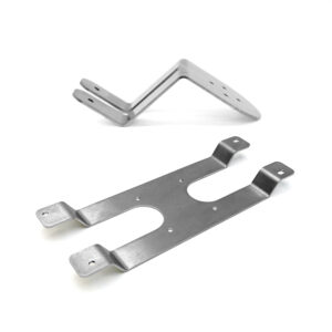
- 1 x DVL A50 Mounting Bracket
- 1 x 2 mm hex driver
- 1 x 3 mm hex driver
- 4 x M3x5 button head cap screws (included with mounting bracket)
- 2 x M5x16 button head cap screws (included with mounting bracket)
- 1 x Power drill and a 5.50 mm, or 7/32″, drill bit
- 1 x Marking pen
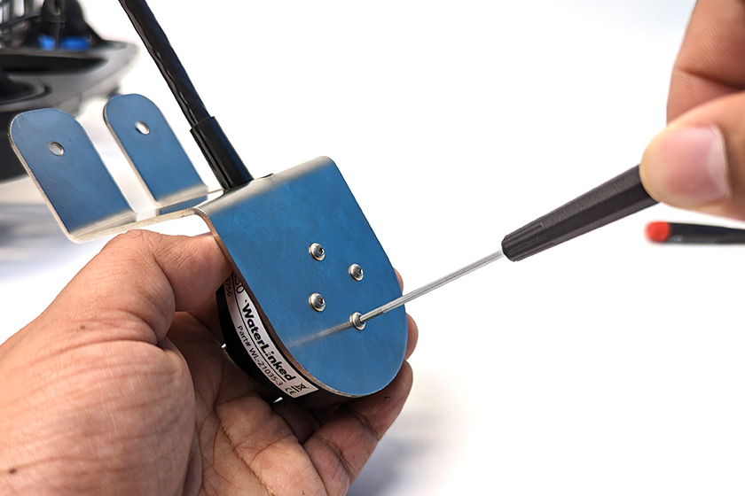
1. Use the four M3x5 button head cap screws and the 2 mm hex driver to secure the DVL to the mounting bracket. Orient the DVL on the bracket so that the cable is routed through the middle cutout.
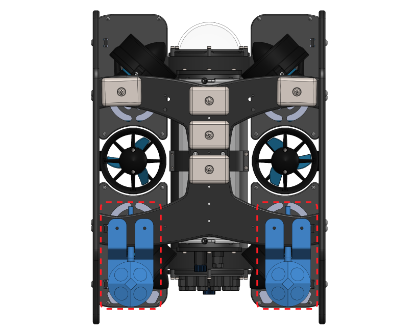
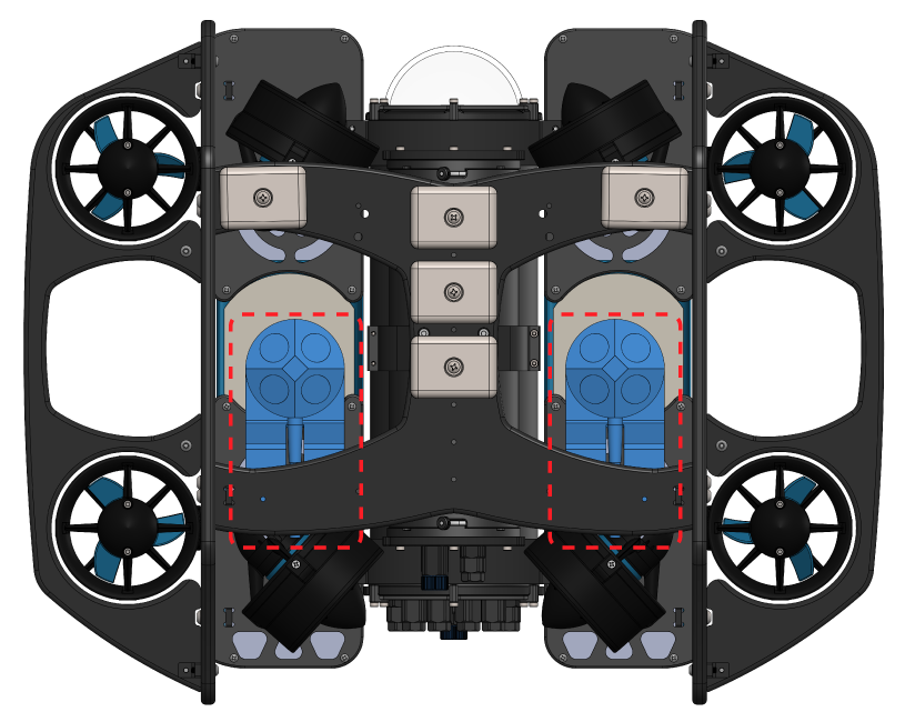
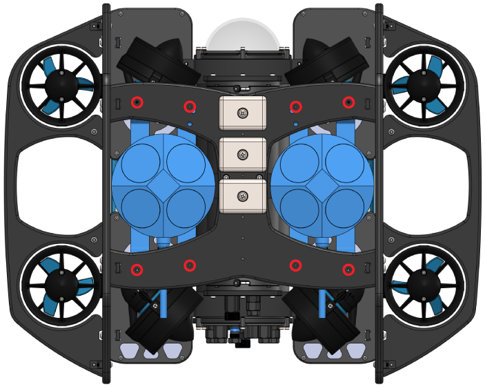
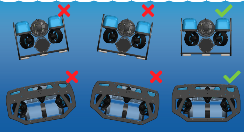
2. The suggested mounting locations for the DVL A50 are shown below. Take note that the mounting location is different for the standard BlueROV2 and a BlueROV2 Heavy Configuration.
Standard BlueROV2
BlueROV2 Heavy Configuration
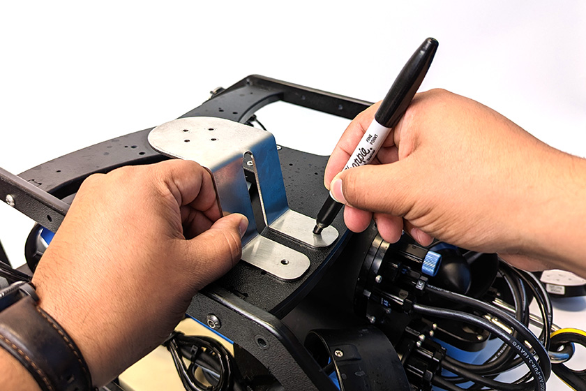
3. After you have decided on a location to mount the DVL, flip the ROV upside down and use the mounting bracket as a template to mark the placement of the two M5 holes using the marker.
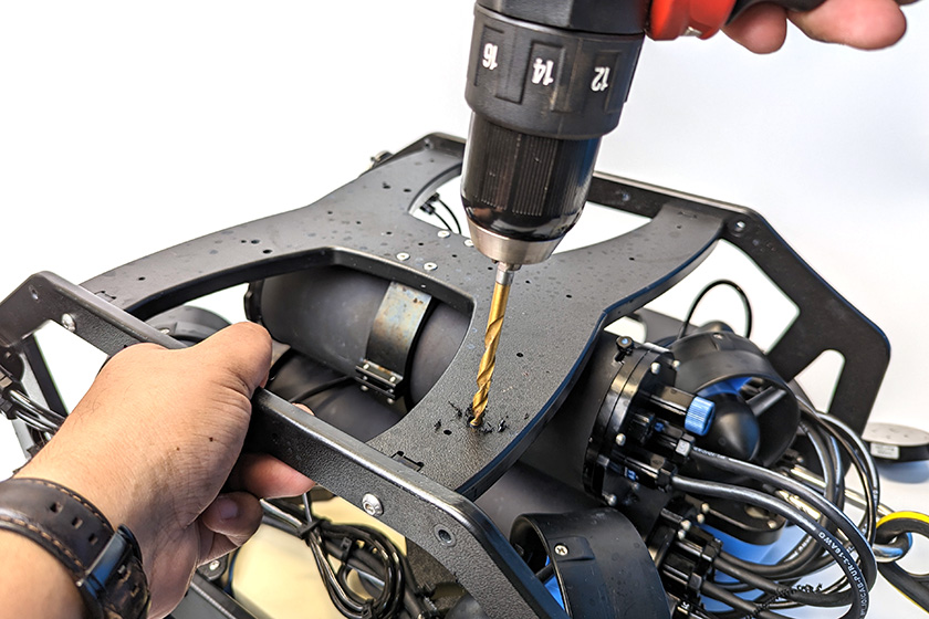
4. Use the power drill to drill mounting holes straight through the bottom frame panel.
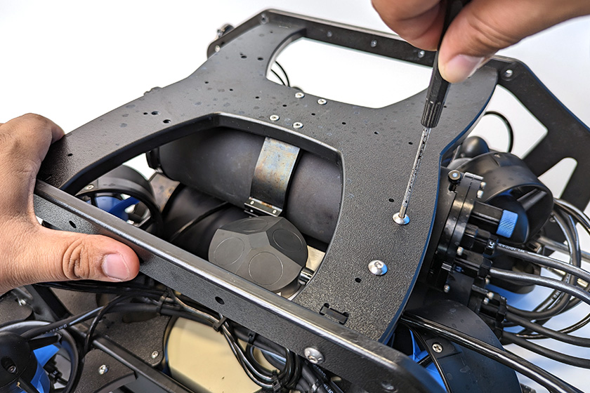
5. Use the 3 mm hex driver and the M5x16 screws to secure the mounting bracket to the frame. The screws should go through the bottom panel and screw into the mounting bracket on the other side. Keep in mind the appropriate mounting position for your ROV. The BlueROV2 Heavy Configuration mounting location is shown in the picture below.
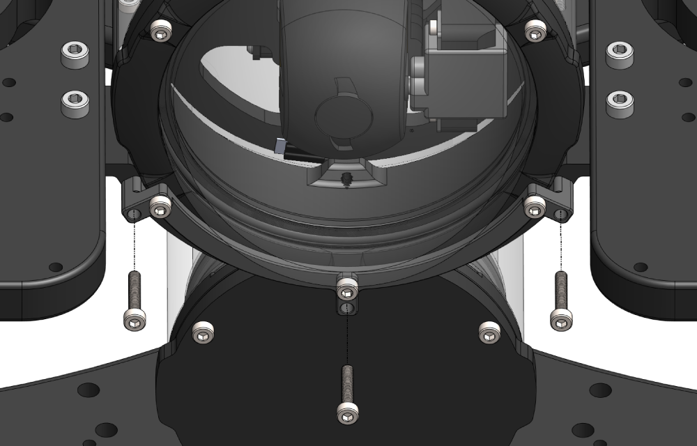
Mounting the DVL A125
To mount the DVL to the BlueROV2 frame, you will need:
- 1 x DVL A125 Mounting Bracket
- 1 x 2.5 mm hex driver
- 1 x 3 mm hex driver
- 1 x #2 Phillips head screwdriver
- 4 x M4x6 button head cap screws (included with mounting bracket)
- 4 x #8-18×3/4″ thread-forming screw (included with mounting bracket)
1. The mounting bracket is mounted using the existing ballast mounting holes shown below.
Decide which side of the ROV to install the DVL then remove any ballast weights from the bottom panel that are secured using those mounting holes.
2. The BlueROV2 bottom frame panel must be temporarily removed to install the DVL. Use a 3 mm hex driver to remove the four screws securing the bottom frame panel. Watch out for the slot nuts as they like to fall out and get lost!
3. The mounting bracket will only align with all four mounting holes in one direction. Align the mounting bracket to the mounting holes to determine the correct orientation of the bracket.
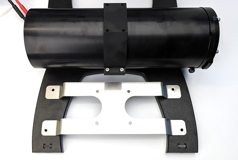
Once you’ve determined the correct orientation for the bracket, use the 2.5 mm hex driver and four M4x6 screws to secure the DVL to the bracket. The DVL must be oriented so the cable exits towards the rear of the ROV.
4. Place the bracket on top of the bottom panel with the DVL facing down. Use a #2 Phillips driver and the thread forming screws to secure the bracket to the bottom panel. Start with the circular mounting holes. The screws will go through the bracket and thread into the bottom panel plastic.
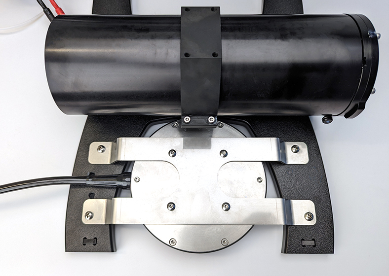
5. Reattach the ROV bottom panel.
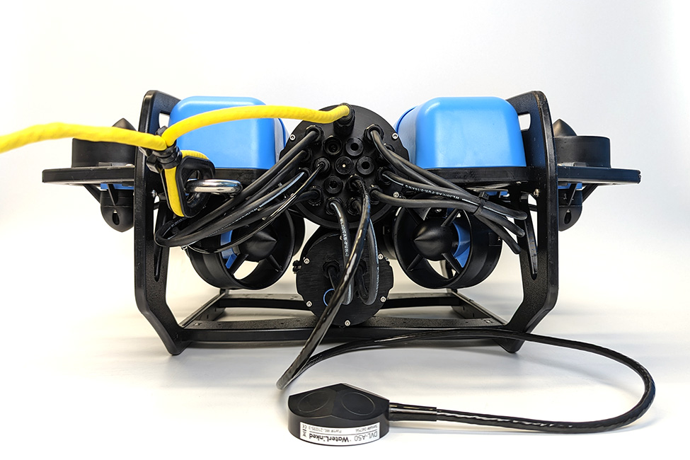
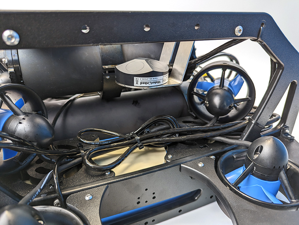
Cable Management
The goal of good cable management is to neatly secure all loose cables to the ROV frame, ensuring they are protected from potential damage by the thruster propellers or entanglement during operation. Use cable ties to attach the cables firmly to the frame, ensuring no cable is left loose. After securing the cables, verify that none can come into contact with any thruster propellers.
Adjusting the Ballast on the Frame
The DVL and bracket add some weight to the BlueROV2 frame so the ROV ballast will need to adjusted to keep it neutrally buoyant and balanced in the water. Remove or relocate the ballast weights on the bottom of the frame to adjust the ballast. You can view complete instructions for adjusting the ballast in the ‘Servicing the BlueROV2’ section of the BlueROV2 Operation guide.
Software Setup
To continue with the software setup, power on your BlueROV2 and connect it to your computer.
Updating BlueOS
The DVL requires BlueOS stable version 1.1.1 or later. The BlueROV2 will need access to Wi-Fi in order to perform a software update, make sure you are in an area with a strong and accessible Wi-Fi network before continuing with the update process. To update BlueOS:
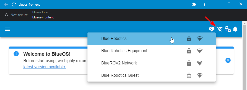
1. Access the BlueOS web interface by typing the IP address 192.168.2.2 or https://blueos.local into the browser address bar.
2. Connect to a wireless network by clicking on an available network from the wireless network menu and entering the password.
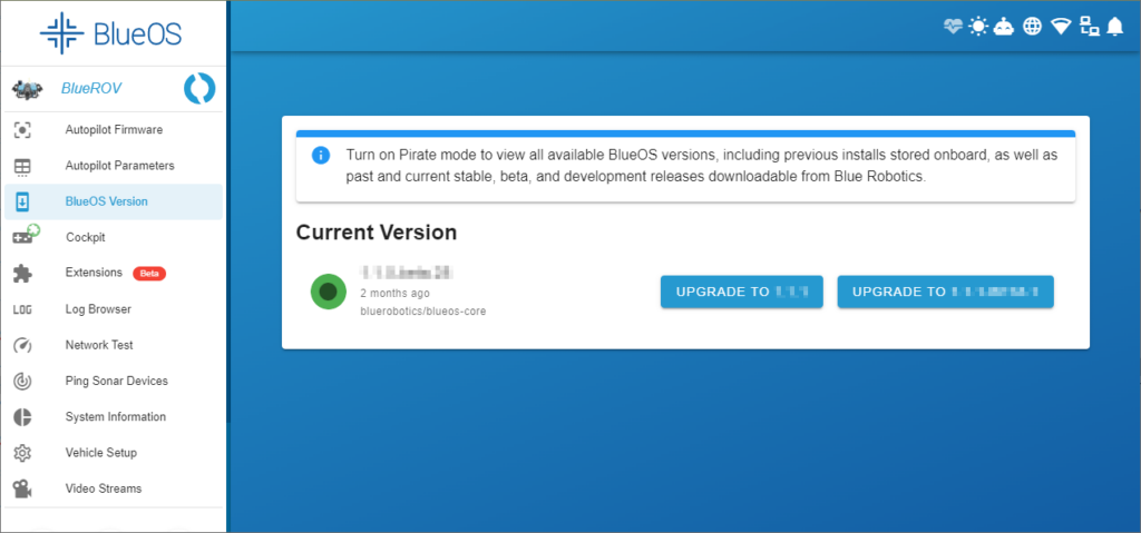
3. Expand the Tools submenu, and select Version Chooser (this may be called BlueOS Version if you a using a newer beta version). You will see an UPGRADE TO button If there is a newer stable version available. You must also be connected to the internet to check for updates. Click on UPGRADE TO to install the update.
Updating ArduSub
The DVL requires ArduSub 4.1.0 or later. To update ArduSub:
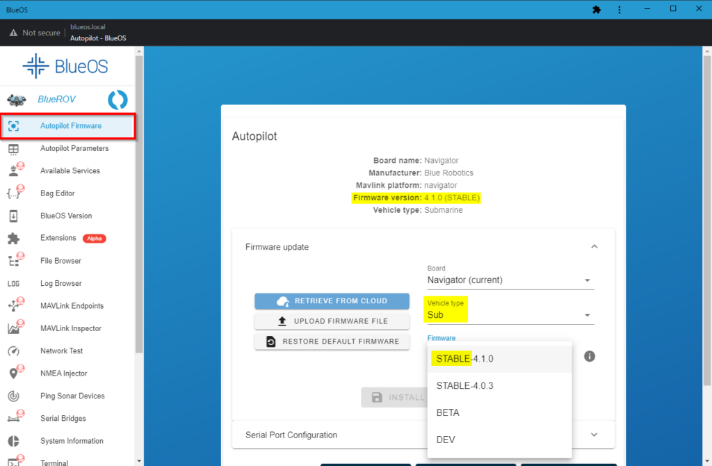
1. Select Autopilot Firmware from the sidebar. The currently installed firmware version (ArduSub version) is displayed at the top of the page. To update the firmware, expand Firmware update, select “Sub” from the Vehicle type dropdown menu and select the latest “STABLE” version from the Firmware dropdown menu. Select INSTALL FIRMWARE to install it. You can skip this if the latest STABLE matches the currently installed firmware version.
Installing the Water Linked DVL Extension
1. Select Extensions from the BlueOS sidebar. Find the Water Linked DVL extension, select it and click INSTALL.
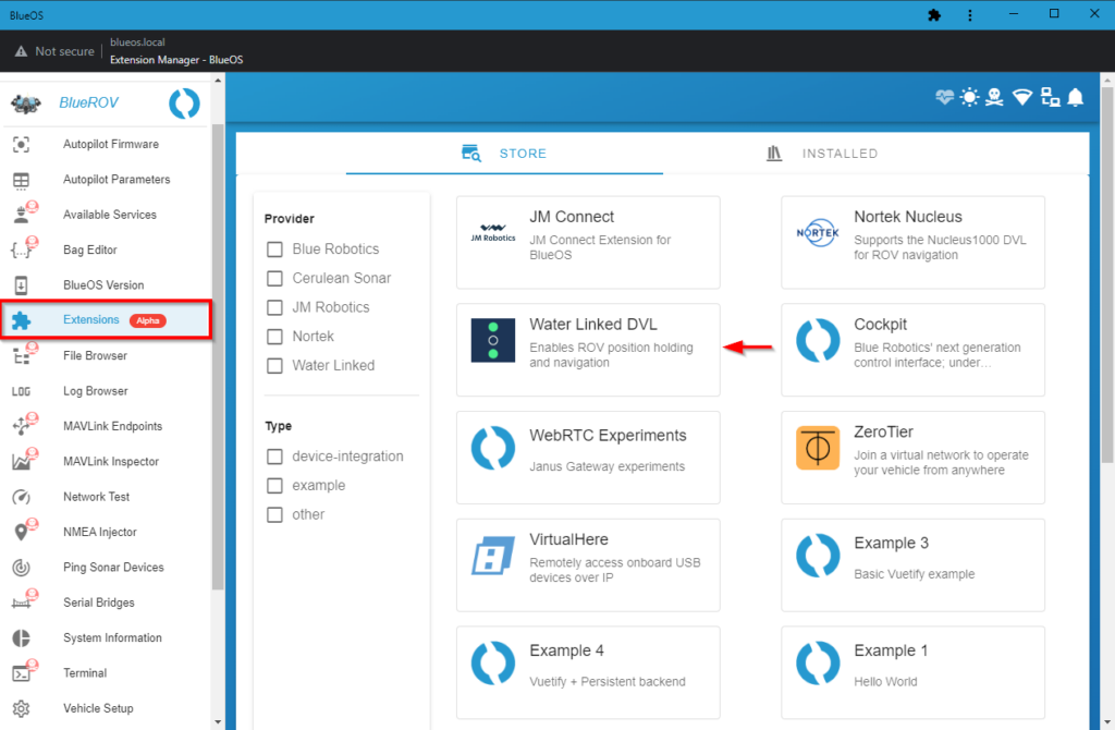
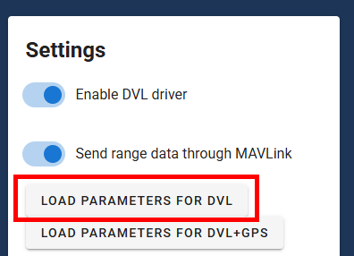
2. After the extension is installed, launch it from the left sidebar. Select LOAD PARAMETERS FOR DVL to set the required vehicle parameters.
- If you are using the DVL together with the Water Linked UGPS, choose LOAD PARAMETERS FOR DVL+GPS instead.
The changed parameters are listed below for reference:
| Parameter | Value |
|---|---|
| EK3_ENABLE | Enabled |
| AHRS_EKF_TYPE | Enable EKF3 |
| EK2_ENABLE | Disabled |
| VISO_TYPE | MAVLink |
| EK3_SRC1_POSXY | ExternalNav |
| EK3_SRC1_VELXY | ExternalNav |
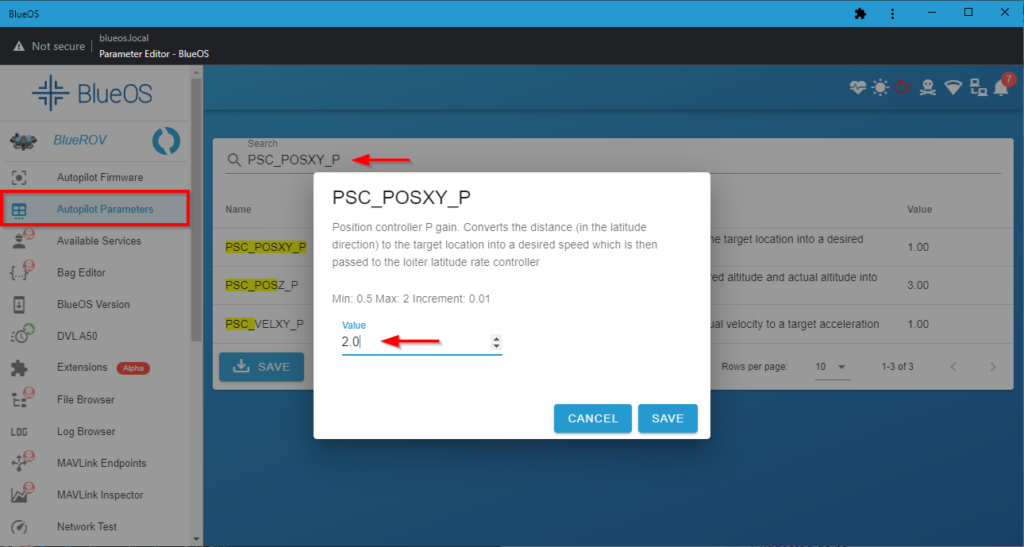
3. The following table lists the suggested PID values for use with the DVL. If you have tuned and set custom PIDs for your ROV, you are free to continue using your own PID values if you choose to do so. Otherwise, if you don’t know what any of that means, go ahead and set the PIDs as follows:
| Parameter | Value |
|---|---|
| PSC_POSXY_P | 2.0 |
| PSC_POSZ_P | 1.0 |
| PSC_VELXY_D | 0.8 |
| PSC_VELXY_I | 0.5 |
| PSC_VELXY_P | 5.0 |
| PSC_VELZ_P | 5.0 |
Select Autopilot Parameters from the BlueOS sidebar. On the parameters page, enter the parameter name from the table into the Search bar. Select the correct parameter and enter the corresponding value into the Value field. Click SAVE to save it.
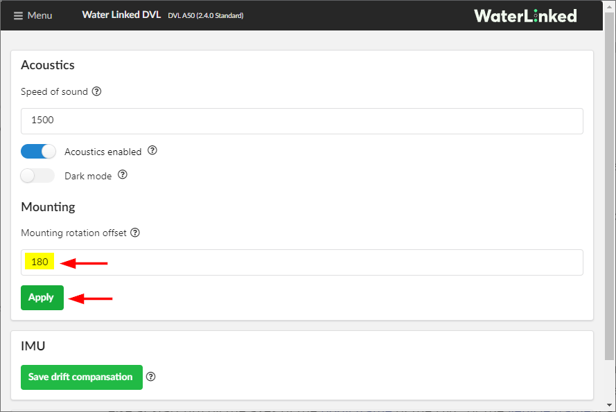
Set Mounting Rotation Offset
If you are using the suggested mounting position for the standard BlueROV2 (shown below), the DVL is facing backwards and the mounting rotation offset needs to be corrected in the DVL settings. If your DVL is facing forward, like on a BlueROV2 Heavy Configuration, skip this step.
1. Access the Water Linked DVL web GUI by typing the IP address 192.168.2.95 into a browser address bar.
2. In the Water Linked DVL web GUI, open the menu on the left side and select Configuration.
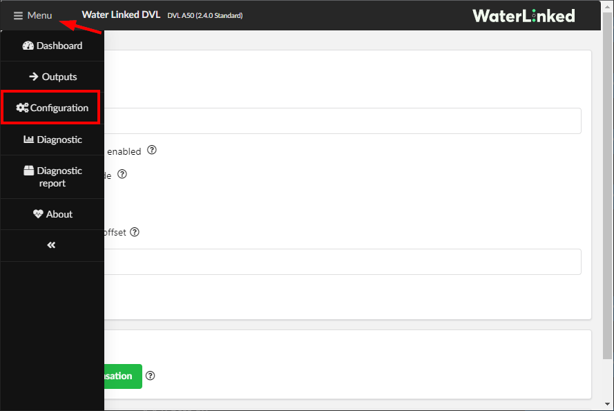
3. On the configuration page, enter “180” for the Mounting rotation Offset setting and click Apply to save it.
Using the DVL A50 and A125
The DVL enables three position-enabled flight modes for the BlueROV2:
- Position Hold Mode: The ROV will hold its heading, depth, and location when not commanded to move.
- Auto Mode: The ROV will follow a planned mission path consisting of waypoints.
- Guided Mode: The user clicks on a location on the map and the ROV will autonomously travel to it.
It also enables a live view of the ROV’s location in the QGroundControl Map View. The following sections explain how to use each flight mode in more detail.
Position Hold Mode
Position Hold flight mode is enabled by pressing a button on the controller just like the standard Depth hold and Stabilized flight modes. The picture below shows an example layout with the middle Xbox button set to enable Position Hold mode, however, you can customize the button layout to your preference.
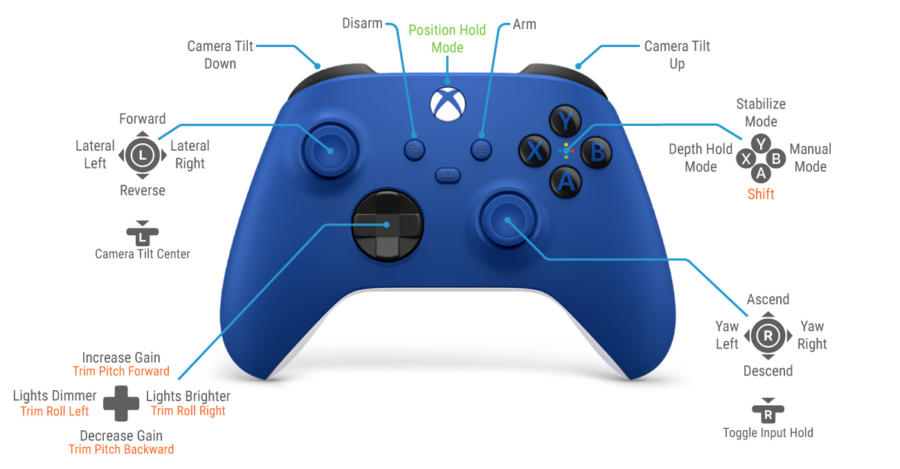
Choose the button that you would like to use to enable Position hold and set its button function to mode_poshold in QGroundControl by following the ‘Changing the Button Setup’ instructions.
During operation, press the Position Hold button to switch to Position Hold flight mode. With Position Hold enabled, the BlueROV2 will hold depth, maintain heading, and hold its position when not commanded to move by pilot controller input.
Relative vs. Global Position
The DVLs use a dead reckoning algorithm to estimate orientation and position. They do not use an external source like GPS to determine global position. Instead, they track velocity and movements to estimate the current position relative to an initial starting position. For Auto and Guided flight modes, the ROV’s starting position coordinates can be manually set by clicking the location on the map in the WaterLinked DVL BlueOS extension.
The ROV will use this starting position for subsequent waypoint navigation in Auto and Guided modes. The ROV will dutifully follow a planned waypoint mission, but keep in mind it will do so relative to its actual starting position, which may not precisely align with the selected position on the map. To obtain accurate global positioning of the ROV on the map, a global positioning system such as GPS or USBL is necessary.
Setting the ROV's Starting Position
The ROV’s initial starting position must be set before it is displayed the QGroundControl Map View. Setting the starting position is also required before Auto and Guided flight modes can be used. To set the starting position:
1. Launch the ROV and navigate to the location that you would like to set as the starting position. Set the ROV to Position Hold mode.
2. Open the Water Linked DVL extension in BlueOS. Zoom into your location on the displayed map. Click on a location on the map to use as the ROV’s starting position. Try to be as accurate as possible as the ROV will use this starting position for all autonomous navigation. Click Set Vehicle Position to set the position.
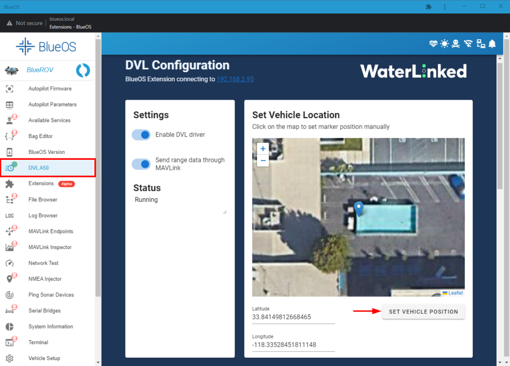
3. After setting the starting position, the ROV’s location will be displayed on the QGroundControl Map View.

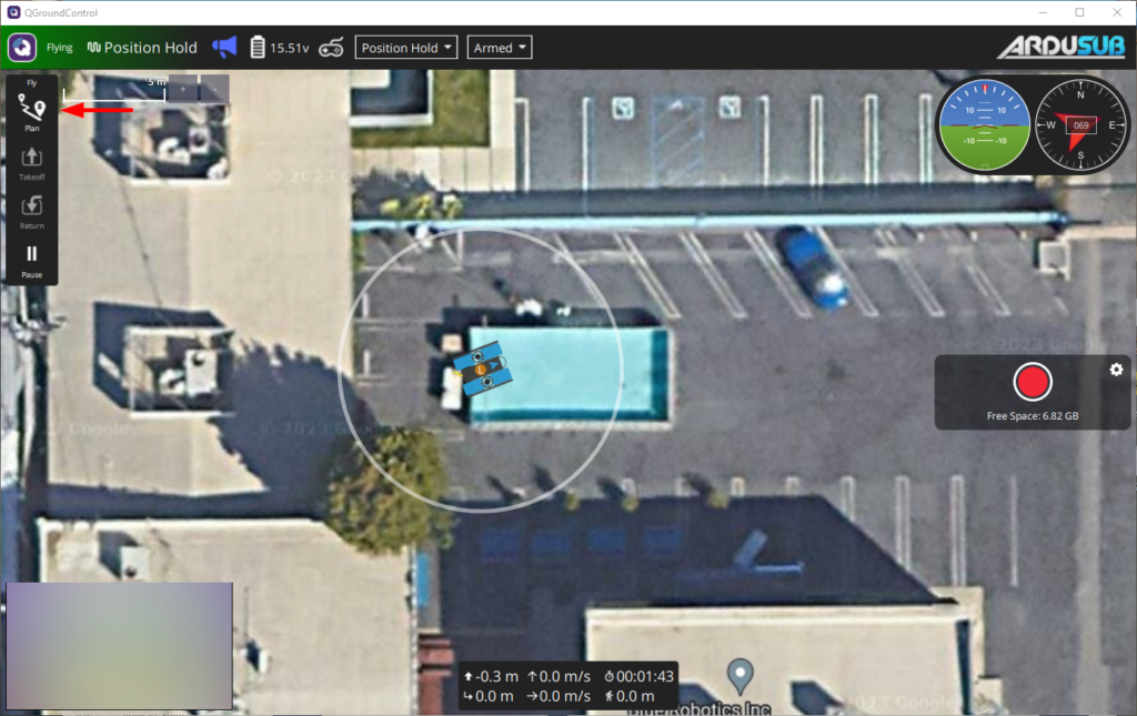
Auto Mode
Auto Mode allows you to execute a planned mission defined in the QGroundControl Plan View. This section will show you how to plan and execute your first simple mission.
1. Set the ROV’s starting position according to the instructions in the ‘Setting the ROV’s Starting Position’ section.
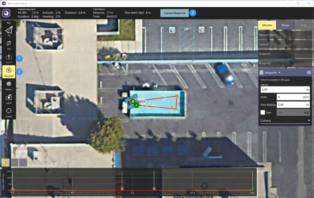
2. While the ROV is still in position hold mode, go to Plan View and select the basic mission option.
3. In the Mission Start panel on the right side, change the starting altitude to 0. Click on the Takeoff tool from the Plan Tools on the left side, this sets the takeoff point at the ROV’s current starting position.
4. After setting the takeoff point, select the Waypoint tool to activate it. While active, clicking on the map will add a new mission waypoint at the clicked location. Click on a couple of locations to add a waypoint there. As you add waypoints, they are added to the Mission Command List on the right side. From the Mission Command List, you can set the depth for each waypoint in the Altitude text field (use negative values for depth). Add the last waypoint in the location you want the ROV to end the mission.
5. Click Upload Required when you are done planning the mission to upload it to the ROV.
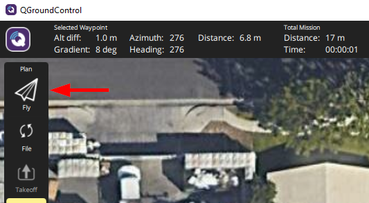
6. Click on Fly View to exit Plan View. Move the slider on the bottom of the screen when you are ready to execute the mission.
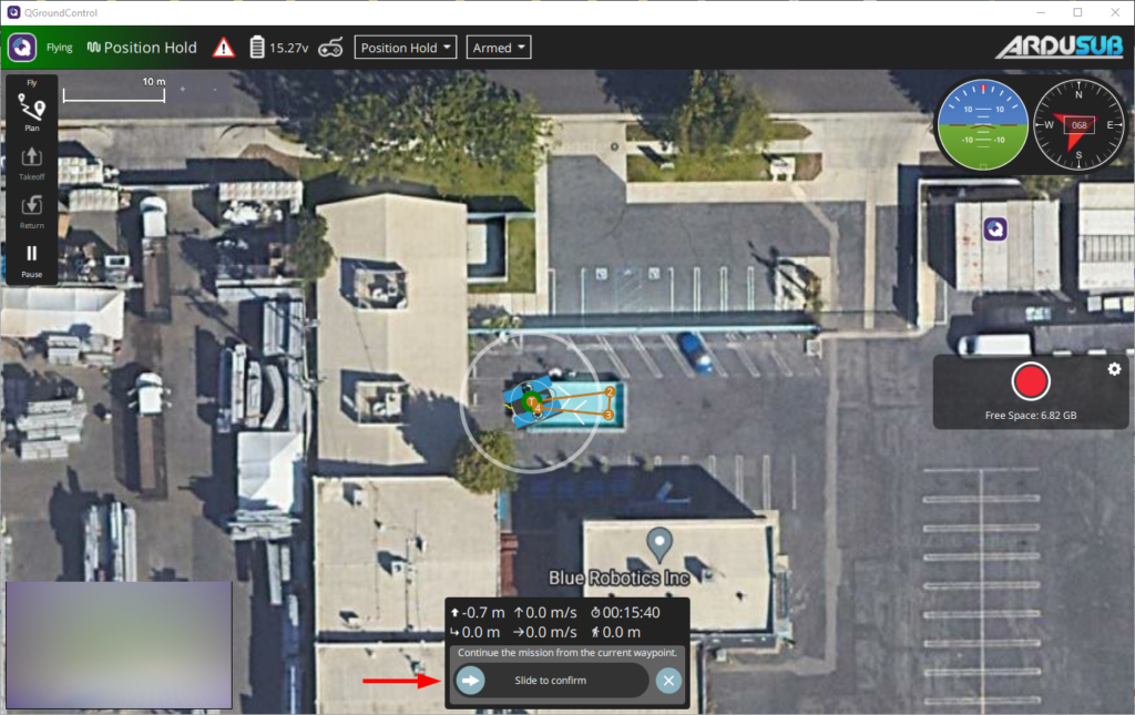
7. Congratulations! The ROV should now be autonomously navigating to each waypoint. When the ROV reaches the final waypoint, disarm the ROV to end the mission. The ROV can be disarmed in the middle of a running mission to immediately stop the mission. You can also regain manual control of the ROV during a mission by changing the flight mode.
Downloading Offline Maps
You may sometimes need to operate in a location that does not have internet access or reliable mobile service. In this situation, the map data for a location can be downloaded beforehand for later use. To download an offline map in QGroundControl:
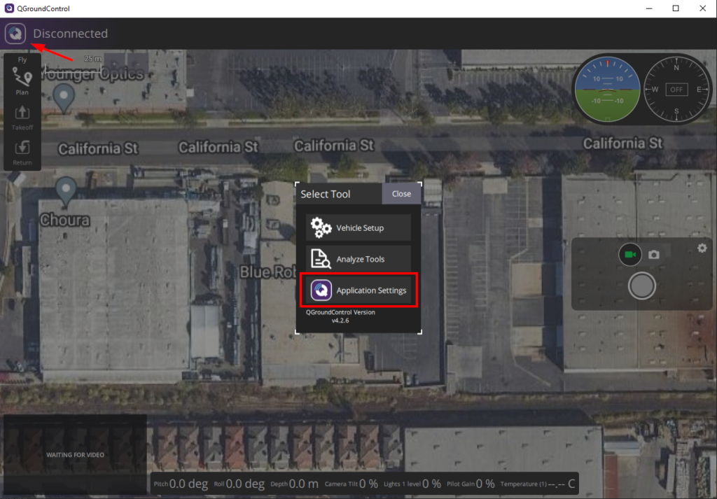
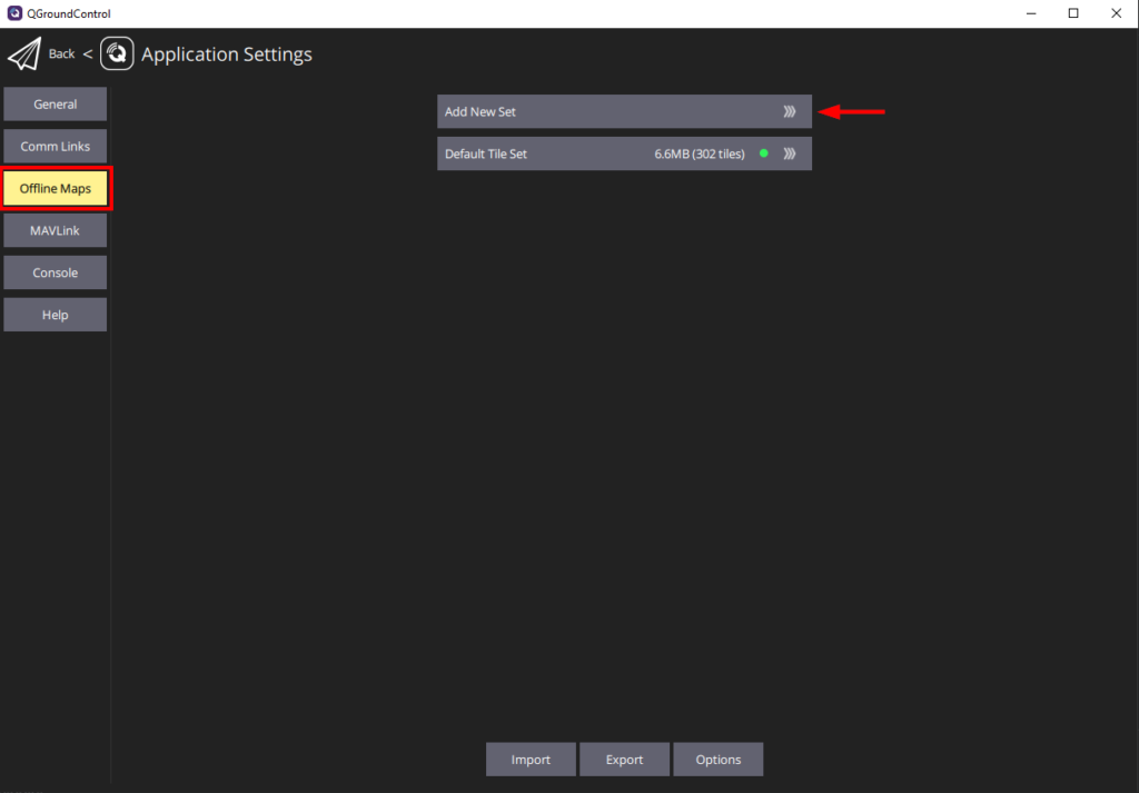
1. In the QGroundControl, position the Map View in the general area of the map you would like to download. Click on the “Q” icon in the top left corner and select Application Settings.
2. Select Offline Maps from the sidebar and click on Add New Set.
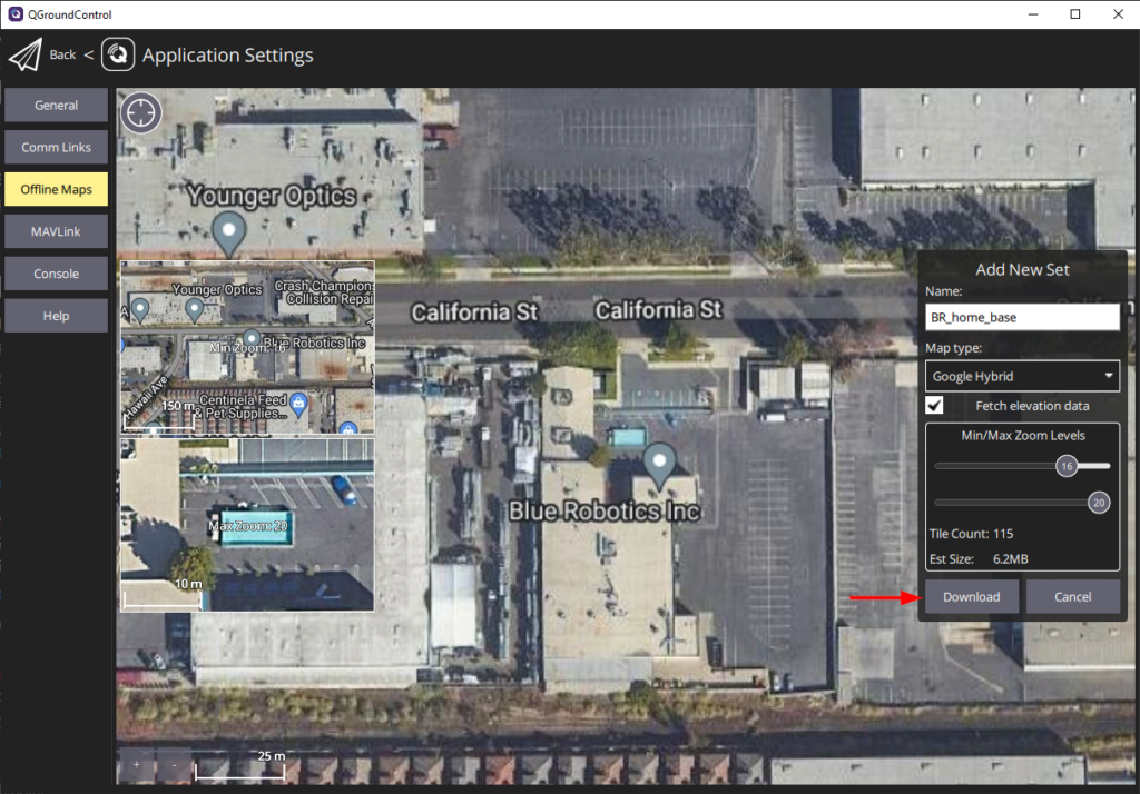
3. The next screen allows you to edit the options for the new offline map. You can edit the name for the new map, change the map type, and set the minimum and maximum zoom levels for the map. You can drag the map to reposition it, a preview of the minimum and maximum zoom levels are also displayed. Click Download when you are done to download the offline map.
Feedback
We’re always trying to improve our documentation, instructions, software, and user experience. If you’d like to leave feedback about how we can make this guide better, let us know here.