
Ethernet Switch Installation Guide for the BlueBoat
Introduction
The Ethernet Switch is a compact network switch that integrates perfectly with the BlueBoat, enabling you to connect Ethernet devices to the BlueBoat network easily.
This guide will show you how to install it in the BlueBoat.
Parts and Tools
You Will Need
You will also need:
- 1 x 2A or 5A mini blade fuse (from BlueBoat kit spares)
- 2 mm hex driver
- Small (~2 mm) flathead (slotted) screwdriver
BlueBoat Installation
Removing the Starboard Hatch Lid Assembly
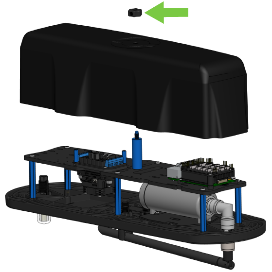
Removing the Starboard hatch lid assembly from the BlueBoat is optional but it makes installing the switch much easier. To remove the hatch lid assembly:
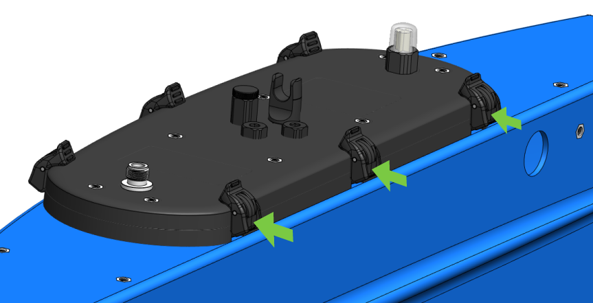
1. Open the starboard side hatch lid by pressing in the latch clips to release the latches.
2. Disconnect all the cables that are connected to it (STBD PWR cable, motor cable, ESC signal cable) and remove it from the BlueBoat.
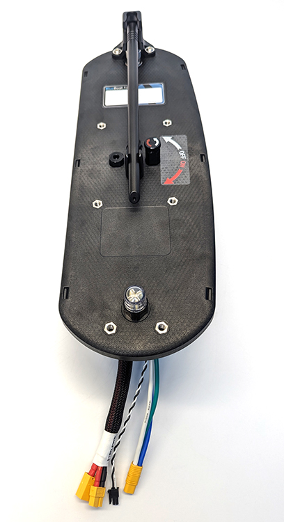
3. Remove the hatch lid clamshell (cover) by unscrewing the thumb nut. This gives you access to the electronics on the electronics tray.
Installing the Ethernet Switch
To install the Ethernet Switch in the BlueBoat you will need:
- 1 x 2A or 5A mini blade fuse (from BlueBoat kit spares)
- 1 x 150 mm Ethernet cable (from Ethernet Switch kit)
- 1 x 2-position JST GH to ferrule power cable (from Ethernet Switch kit)
- 2 x M3x5 button head mounting screws (from Ethernet Switch kit)
- 2 mm hex driver
- Small (~2 mm) flathead screwdriver
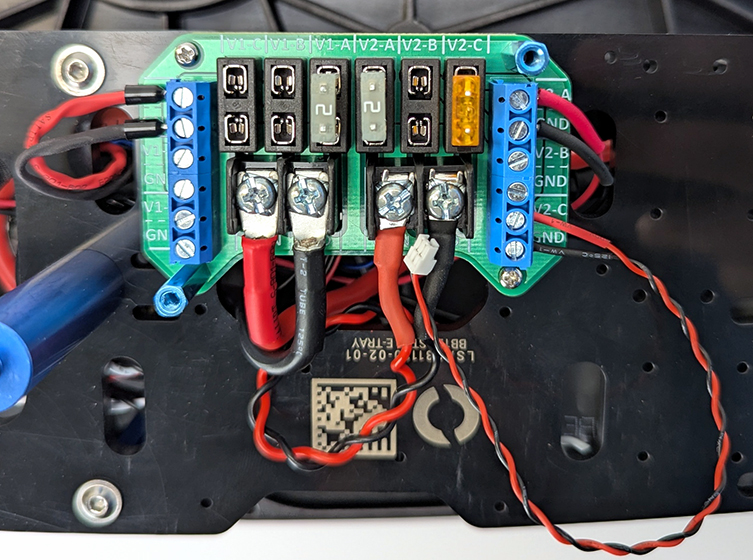
1. Connect the Ethernet Switch power cable ferrules to an available output on the fuse board. It can be connected to either the full voltage side (V1) or the 5-volt side (V2). Since many BlueBoat payloads use the V1 side, using V2 may help save space for other devices. Connect the black wire to an output labeled “GND” and the red wire to a voltage output. Use the small flathead screwdriver to loosen and tighten the connectors as needed.
2. Install the fuse in the corresponding slot at the top of the fuse board. For example, in the picture below, the power cable is connected to the “V2-C” output, so the fuse is installed in the “V2-C” slot.
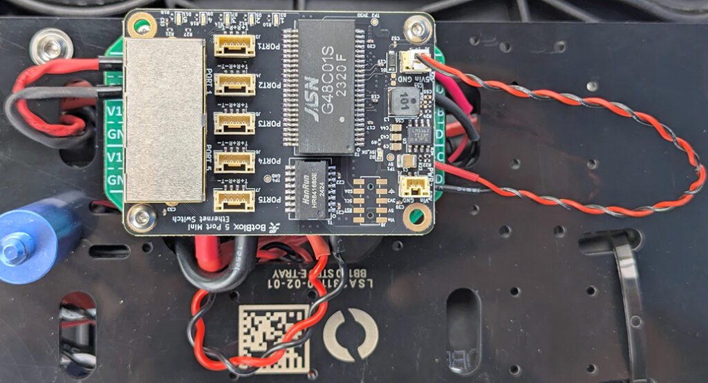
3. Use two M3x5 button head screws and the 2 mm hex driver to mount the Ethernet Switch on the fuse board standoffs. Mount the switch so the RJ45 (Ethernet) ports are facing the Raspberry Pi.
4. Connect the power cable to the Ethernet Switch. If you connected the power cable to the V1 side, connect it to the input labeled “PWR 7-52V”. If you connected the power cable to the V2 side, use the input labeled “5Vin GND”. Do not connect the power cable to the wrong power input. In the example below, the power cable is connected to the “5Vin GND” input.
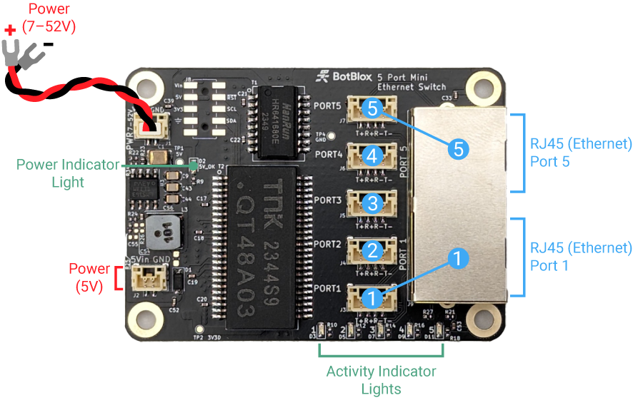
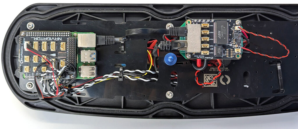
5. Disconnect the Ethernet cable from the Raspberry Pi and connect it to port 5 on the Ethernet Switch. Take the short Ethernet cable and connect the Raspberry Pi to port 1 on the Ethernet Switch.
6. Now is a good time to test your connection before adding any additional devices.
Connect the hatch lid assembly power cables to the BlueBoat, plug in a battery, and power on the BlueBoat. The “5V_OK” LED on the Ethernet Switch should illuminate and the activity LEDs for ports 1 and 5 should begin blinkinb after a few seconds.
Next, connect the BlueBoat to your BaseStation and computer and verify that you can establish a connection. If everything is working normally, you’re ready to connect additional devices to the Ethernet Switch! If you’re having trouble establishing a connection, continue to the Troubleshooting section below.
Connecting Devices
The Ethernet Switch is an unmanaged switch so no additional configuration is required. Just connect a device and the switch will automatically begin forwarding packets.
There are a total of 5 ports on the Ethernet Switch. When installed in a BlueBoat, the Wi-Fi router and Raspberry Pi occupy ports 1 and 5. This leaves ports 2, 3, and 4 open to connect other Ethernet devices.
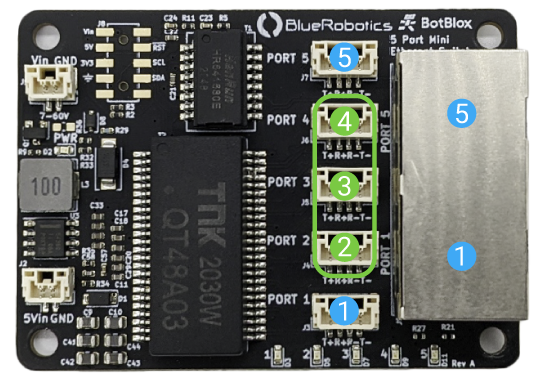
JST GH Connector Pinout
The JST GH connectors for ports 1–5 follow the Blue Robotics Connector Standard for Ethernet connections:
| Recommended Connector | Pin # | Signal | Recommended Wire Colors |
|---|---|---|---|
| JST GH (4 position) Part #: BM04B-GHS-TBT(LF)(SN)(N) SM04B-GHS-TB(LF)(SN) | 1 | TX+ | White/orange |
| 2 | RX+ | White/green | |
| 3 | RX- | Green | |
| 4 | TX- | Orange |
Cable Connections
An RJ45 to JST GH adapter board is included in the Ethernet Switch kit.
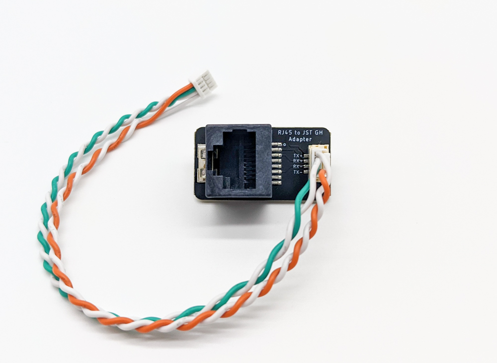
RJ45 to JST GH adapter
This adapter makes it easy to connect Ethernet devices that use a standard RJ45 connector to the switch. Additional RJ45 to JST GH Adapter Boards can be purchased separately here.
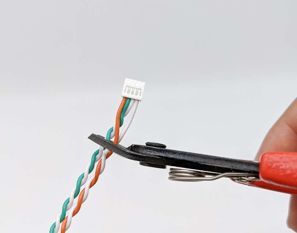
The Ethernet Switch kit also includes multiple JST GH to JST GH twisted pair cables that can be used to connect devices. Clip one end of a JST GH to JST GH twisted pair cable and solder splice it to the device cable following the Blue Robotics Connector Standard for Ethernet connections, then plug it directly into a port on the switch.
Troubleshooting
Cannot connect to BlueBoat
- Check the “5V_OK” power indicator light on the Ethernet Switch. If it is off:
- Check if the power connector is fully seated and the ferrule connectors are connected correctly to the fuse board.
- Check that a fuse is connected to the correct fuse slot on the fuse board.
- Check the activity indicator lights for ports 1 and 5. If they are not illuminated, check that the Ethernet cables are properly connected and the devices are powered on.
- If the Wi-Fi router and the Raspberry Pi are connected to the RJ45 jacks on ports 1 and 5, make sure no other devices are connected to the JST GH connectors on the same ports.
Cannot connect to a device
- Check the activity indicator light for the port the device is connected to. If it is not illuminated, check the cable connections and make sure the device is powered on.
- Make sure multiple devices are not connected to both the JST GH connector and the RJ45 jack on ports 1 and 5.
- Check your device’s IP or network configuration.
If you are still having issues with the Ethernet Switch, get in touch with our support team at [email protected].
Feedback
We’re always working to make our documentation, instructions, software, and user experience even better. If you have any ideas on how we can improve this guide, feel free to let us know here.