
Connecting Your Device with Navigator and BlueOS
Introduction
Many payloads, such as CTD Sondes and Sonars, use a serial protocol for communication. Common types include RS232, RS485, and RS422. Other payloads use different interfaces, such as USB or Ethernet, to allow for more data bandwidth. Many small sensors intended to interface directly with a microcontroller use the I2C communication protocol. Once your device is connected, you may want to do something with the data! If writing code to talk with your payload seems daunting, often Node-RED can come to the rescue!
These protocols transmit data streams in different formats, like NMEA or the Ping Protocol. In this guide, we detail methods to receive these data streams and connect them to computers using the Blue Robotics BlueROV2, BlueBoat, or any Navigator / BlueOS-based vehicle. Let’s dive in!
You will need
To complete the setup for your system, you will need the following components:
- Your vehicle with Navigator installed
- Connection to vehicle (via FXTI, BaseStation, or any TCP/IP link)
- Your computer
- Appropriate hardware for your device (see table)
Common ways things talk:
| Device Communication Method | Requirement | Pin Names | Typical Data rates | Typical / Max cable length |
|---|---|---|---|---|
| Serial RS232 | MAX IC or USB Adapter | TX, RX, GND, V | 9.6/115.2/576 Kbit/s (dependent on cable length) | 9.1 m or 30 dt / 15.25 m or 50 ft |
| Serial RS485 / RS422 | MAX IC or 422 / 485 USB adapter | A, B, GND, V | 0.1 / 10 Mbit/s | 100 m / 1200 m or 4000 ft |
| I2C | No device address conflicts, sometimes level shifter | SCL, SDA, GND, V | 0.1/0.4/1 Mbit/s (very dependent on cable length) | 0.3 m or 1 ft/ 10-50 m or 30-165 ft with additional hardware |
| Ethernet | Ethernet Switch or USB Adapter | RX +, RX-, TX+, TX- | 10/100 Mbit/s 1 Gbit/s (compatible tether adapter and devices only) | 50 m or 165 ft / 100 m or 328 ft |
| USB | None (Hub if more ports required.) | D+, D-, 5V, GND | 480 Mbit/s USB2.0 5 Gbit/s USB3.0 | 2 m or 6.5 ft / 5 m or 16 ft USB 2.0 1 m or 3.3 ft / 3 m or 9.8' USB 3.0 |
Serial devices
This guide focuses on how to connect payloads, but if you want to learn everything about serial signals, check out this great resource. Understanding the differences between all the recommended standards, is quite complex!
USB serial adapter
A USB adapter often provides the easiest connection for RS422 signals. For RS485 and RS232, you could use the BLUART, but it does not support the higher voltages used in many serial payloads, so you’ll still need to convert the signal as detailed in the section below. The labels TX (transmission), RX (receive), and GND (ground) represent the signals. You’ll need to connect your payload device’s TX signal line to the appropriate RX signal line of the USB adapter, and similarly the device RX to the adapter TX. When troubleshooting a connection, swapping these two wires is often the best first step! You’ll also need to connect the GND of the adapter and the payload, so the signals are referenced to a common level. You must make your payload power (and ground) connections separate from this referencing link.
A great way to test your wiring before installation in the vehicle is to connect the adapter to your computer and verify any vendor software functions as expected, such as receiving the data in a serial terminal program. With that verified, you can move on to BlueOS Configuration!
Navigator hardware serial ports
The Navigator has labeled ports of Serial 1, 3, 4 & 5. Ports 3 & 4 are generally the best to use when connecting your payload, to keep Serial 1 free for potential RC Radio use. Serial 5 is commonly used by a vehicle’s GPS, as with the BlueBoat.
Converting serial protocol to TTL levels with MAX
The signal protocols typically used for standard serial connections are designed to travel long distances along cables. The standard for RS232 shows that signals sent with the protocol are ±15V – yes that’s negative 15 volts! Connecting this signal directly to either USB or serial ports of the Navigator/Raspberry Pi combo would damage the system. It’s often easiest to use a USB to RS232 adapter, as linked in the table above.
To convert the signals from higher & negative voltages to TTL levels, a MAX series chip is typically used. These will convert the signals to the TTL voltage level they are powered with. You will need to connect the TX and RX from the Navigator to the converter circuit, along with the GND and 3.3V. The diagram below details a typical arrangement for RS232, and the adapter to Navigator connection is identical for RS422 and RS485.
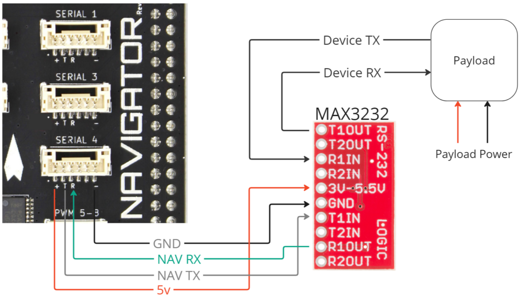
Navigator to MAX series Serial Connection
BlueOS configuration: serial bridges
With the device wired up, it’s time to configure BlueOS! In these instructions, we explain how to use the BlueOS Serial Bridges menu to set up a bidirectional serial to UDP link powered by Bridget. This means your receiving computer will need to access the data at the specified port, via UDP packets. If you are using a USB adapter, you can skip to step 1 & 2 below.
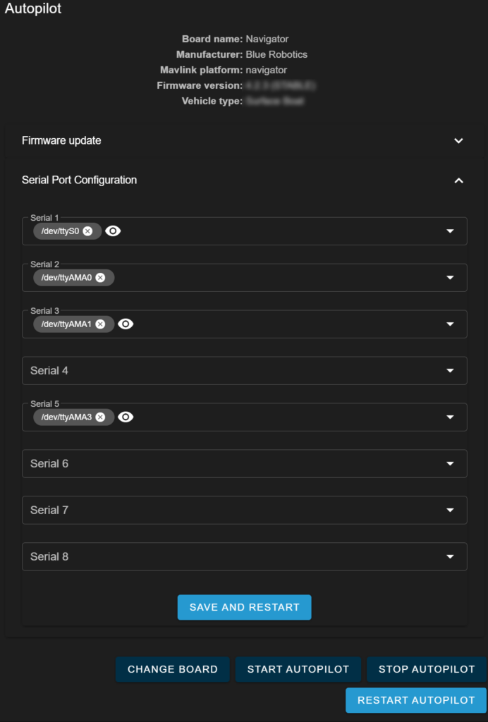
- We’ll first need to make sure the Autopilot is not trying to use the serial port. Select Autopilot Firmware from the top of the menu, and then Select Serial Port Configuration. Click the small X next to the serial Port you intend to bridge. In the screenshot, we’ve removed the configuration for Serial Port 4.
- Click SAVE AND RESTART.
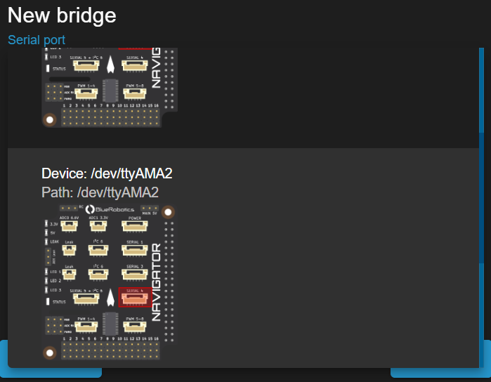
- Next, select Serial Bridges from the menu- you’ll need to be in Pirate mode for this option to appear. Click the “+” button in the lower right to create a new connection.
- Select the Serial Port, which is helpfully illustrated in the drop-down. If you are using a USB Adapter, this will likely appear as /dev/tty/USB0 or similar.
- Now, input the appropriate serial baud rate for the device you’ll be connecting to. Common values are 9600 and 115200, but it is device specific.
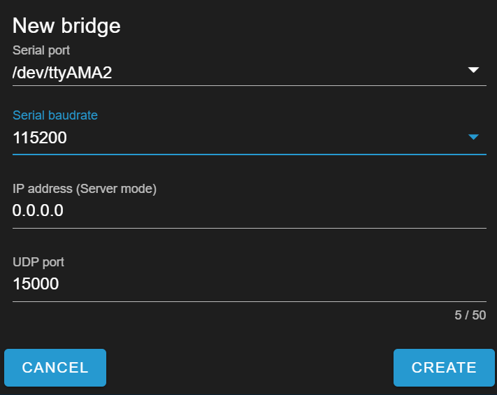
- If you intend to access the serial data stream via UDP Client, leave the IP Address at 0.0.0.0. If you intend for the software on your computer to run as a UDP server when receiving the datastream, input its IP address instead. The advantage to running the bridge as a server is that multiple clients will be able to connect to the serial port simultaneously.
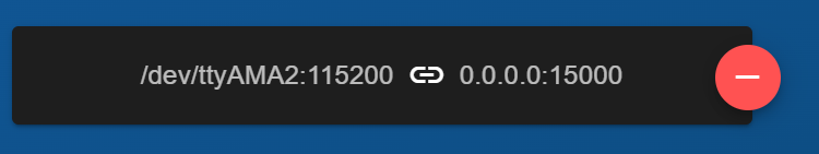
- Finally, select the UDP port you would like to use for the connection. Click Create and your Serial Bridge will be configured!
Testing the serial connection
You can use the NetCat tool to check if data is available on a configured port. It’s installed by default on MacOS and most Linux distributions, as well as Windows via WSL. From your connected computer, run the following command in the terminal application to see the data in real-time.
nc -u blueos.local 15000
You could replace the blueos.local with your system IP if different, and the port # should match what you configured your bridge to use.
Accessing serial stream via UDP with Python
To convert a python script that accesses local serial ports to one that can receive serial data via UDP, check out the socket library. Once you’ve opened the connection, you need to send data to it periodically, every 10 seconds minimum, so the connection is not automatically closed. Here’s an example of how you might modify your script from using a serial device to using a remote serial device accessed via UDP thanks to BlueOS:
import socket

# Set up UDP connection
udp_ip = "192.168.2.2"  # Replace with your UDP server IP
udp_port = 15000       # Replace with your UDP server port

# Create a UDP socket
sock = socket.socket(socket.AF_INET, socket.SOCK_DGRAM)
sock.bind((udp_ip, udp_port))

while True:
    # Receive data from UDP
    data, addr = sock.recvfrom(1024)  # buffer size is 1024 bytes

    # Process data
    # ... Your data processing logic here ...

    # Optionally send data back
    # sock.sendto(bytes_to_send, (udp_ip, udp_port))
I2C devices
The I2C or “I squared C” communications bus functions on circuit boards, transmitting data to and from multiple devices. Long wires, especially in electrically noisy environments, can greatly affect the performance of I2C due to its sensitivity to wire capacitance. This video When connecting multiple devices of the same type to an I2C communications bus, you must follow instructions to change each device’s default address. A multiplexer can assist if you are connecting multiple devices without configurable addresses. You can learn more about I2C here, or with this video. The Raspberry Pi 4 has several different I2C busses – Bus 6 is broken out for external devices. Bus 4 is used with the PWM signal generator that outputs signals to the 16 channels of PWM pins. Bus 1 is used with internal sensors on the Navigator, including the motion sensors and barometer. Bus 6 is the best for user projects, as it is not used by BlueOS or the autopilot firmware.
Supported devices
ArduSub, which the BlueROV2 uses, supports the Bar30 or Bar100 pressure sensors, as well as the Celsius temperature sensor. More sensors could be added, with updates to the Ardusub code. By default, ArduRover, which the BlueBoat uses, does not support any I2C devices. You can access I2C devices using your own Python code with existing libraries. The Linux kernel in BlueOS manages the I2C bus access, ensuring no interference with existing sensor communications.
Extending I2C connection distance
You can use various methods to extend I2C communication range for long wires, sometimes reducing connection bandwidth. The differential signaling and the active terminator method can both extend I2C communication range.
Connecting an I2C device
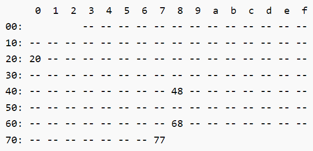
You need to attach Ground, 3.3 Volts, SCL (clock), and SDA (data) lines to any I2C device. The Navigator provides this connection with 2x 4 pin jst-gh connectors and also includes it on the Serial 5 connector. After plugging in, navigate to the BlueOS terminal (in Pirate Mode) and take the red-pill (type red-pill and press enter to gain full root access.) Then you can run:
sudo apt update && sudo apt install -y i2c-tools
i2cdetect -y 6If you consult your sensor’s documentation, you should find its default address listed. For example, 4 discrete devices are connected in this output:
Ethernet devices
BlueOS allows access and use via a TCP/IP Ethernet connection. Using an ethernet switch with BlueOS enables multiple devices to communicate at high data rates. Our Blue Robotics Ethernet switch, which is easy to integrate in the BlueROV2, has a small form factor. However, any ethernet switch will allow communication between connected peripherals. This switch, and most low-cost network switches are “unmanaged” meaning the device is transparent to the user and any devices connected to it. It does not have an IP address, and is simply shuttling packets between plugged in devices.
It is important that systems trying to communicate with each other are using IP addresses of the same subnet – 192.168.2.X, with 255.255.255.0 as the subnet mask is the default configuration for Blue Robotics systems. The control station, or “topside” computer uses an address of 192.168.2.1 in the default Blue Robotics software configuration. As the standard configuration of BlueOS does not include a DHCP server, devices must use a self-/manually-assigned static IP address to communicate.
USB devices
USB/IP extension
This extension is another application of the USBIP project. It supports client machines running Linux or Windows OS. Instructions are available from the Extension installation page. To use this extension, you’ll need to use the terminal on your computer to list remote devices and virtually attach it to your local machine. Install the extension and check the description for more information.
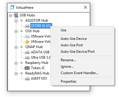
VirtualHere extension
VirtualHere, a commercial program offering a free client with some restrictions, uses the USBIP project. It is compatible with MacOS, Windows, and Linux, and provides a nice GUI tool for configuration. Once the extension is installed, you use the client software on your computer so any USB device plugged into the vehicle Raspberry Pi can be selected for virtual attachment to your computer.
USB cameras
BlueOS supports USB cameras capable of streaming H264 containerized video and adhering to the USB Video Class (UVC) standard. This standard allows for these cameras to be compatible with a wide range of operating systems and software without the need for proprietary drivers or software. You can dip your toes into all things camera gently, or dive in and level up with the advanced usage documentation!
Outputting servo and relay signals
The Navigator has 16 channels of PWM output, managed by a PCA9685PW chip controlled via I2C. These outputs can be controlled directly via the Navigator web assistant extension, but typically users want to control payloads alongside ArduPilot – specifically ArduSub on the Blue ROV2 and ArduRover on the BlueBoat. There are some specific features Blue Robotics has incorporated into ArduSub to make controlling payloads via servo-style PWM easy, these are not yet present in ArduRover.
Servo Devices
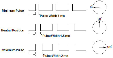
The Navigator sends a 1 to 2 millisecond pulse 200 times a second (200 Hz PWM frequency.) This controls devices that accept servo-style PWM signals like the Newton gripper or camera tilt servo. The Basic ESC also uses this style signal to control the attached motor’s speed and direction. A 1.5 millisecond (1500 microseconds) pulse corresponds to 0 throttle, or the center position of a servo. Many devices accept a minimum of 50 Hz, and up to 400 Hz.
In ArduSub versions prior to 4.5.X, servo channels 9, 10, and 11 are hardcoded to correspond to commands that appear as servo 1, 2, and 3 in QGround Control and Cockpit joystick setup. Note that the ServoFunction for ServoFunction 9,10 and 11 with the older firmware is set to Disabled for things to function properly. Using a device on these three channels is as simple as connecting it (matching the signal wire to the row with the S symbol and white wires coming from the ESCs) and mapping the corresponding servo # channel in your ground control station software to the desired joystick button. For newer versions of ArduSub, >4.5, the ServoFunction parameter for any output channel can be set to Actuator#. This Actuator number can then be mapped in Cockpit to the desired functions! Actions include min and max momentary and toggle (setting the output to 1100/1900 or whatever servo_min and servo_max are mapped to), center (sets output to 1.5 ms, 0 throttle position), and increase and decrease changes the output signal in increments of 50 microseconds (8 steps from 1500 to 1900.) For a full listing of the default servo channel mappings, go here.
Relay Devices
Any available channel output channel can be configured as a relay in both ArduSub and ArduRover. This will send 0V or 3.3V (at <15mA), which can be used to drive external switches or low-power LEDs.
To setup a Relay channel:
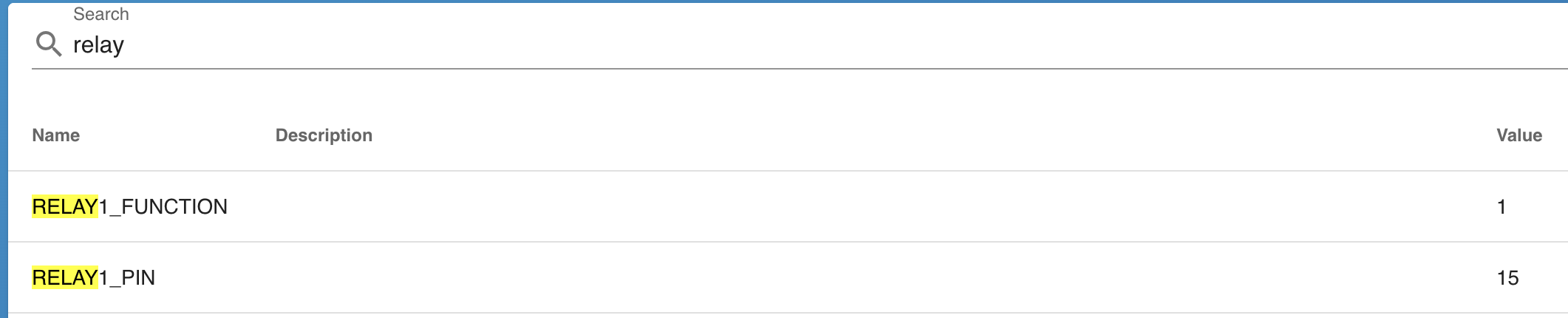
- Navigate to Autopilot Parameters in BlueOS.
- Search for relay in the top bar, and change the desired relay # function to 1 (relay).
- Click the power button icon in the lower left, and restart the Autopilot.
- When the parameters list repopulates, the relay # will have pin and default parameters available.
- The default parameter sets whether the signal output will be high or low on startup, and the pin # corresponds to the output channel of the Navigator. Check the “custom” box to manually input this output channel number, and ignore options in the drop-down.
- You can then map the relay# in Cockpit or QGroundControl to the desired joystick button and action. Actions include momentary (changes state during button press only), toggle (press to change state, latching), and off and on.
Get help
If you’re stuck trying to get a device to communicate, please reach out to our forums! Your experience can benefit others, and we’re eager to help with your application.
What did you think of this guide? Can we improve it? Let us know here!