From: $320.00

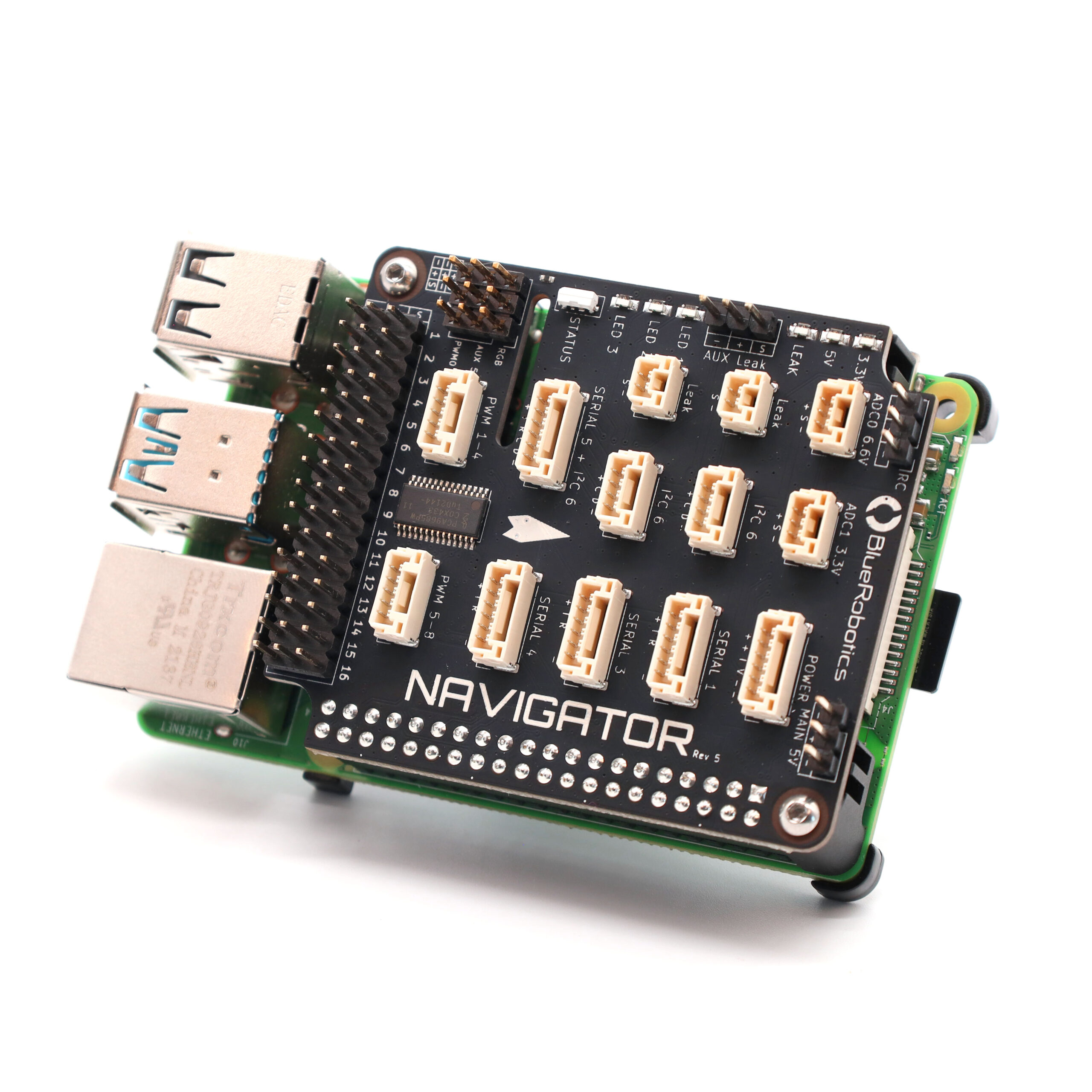
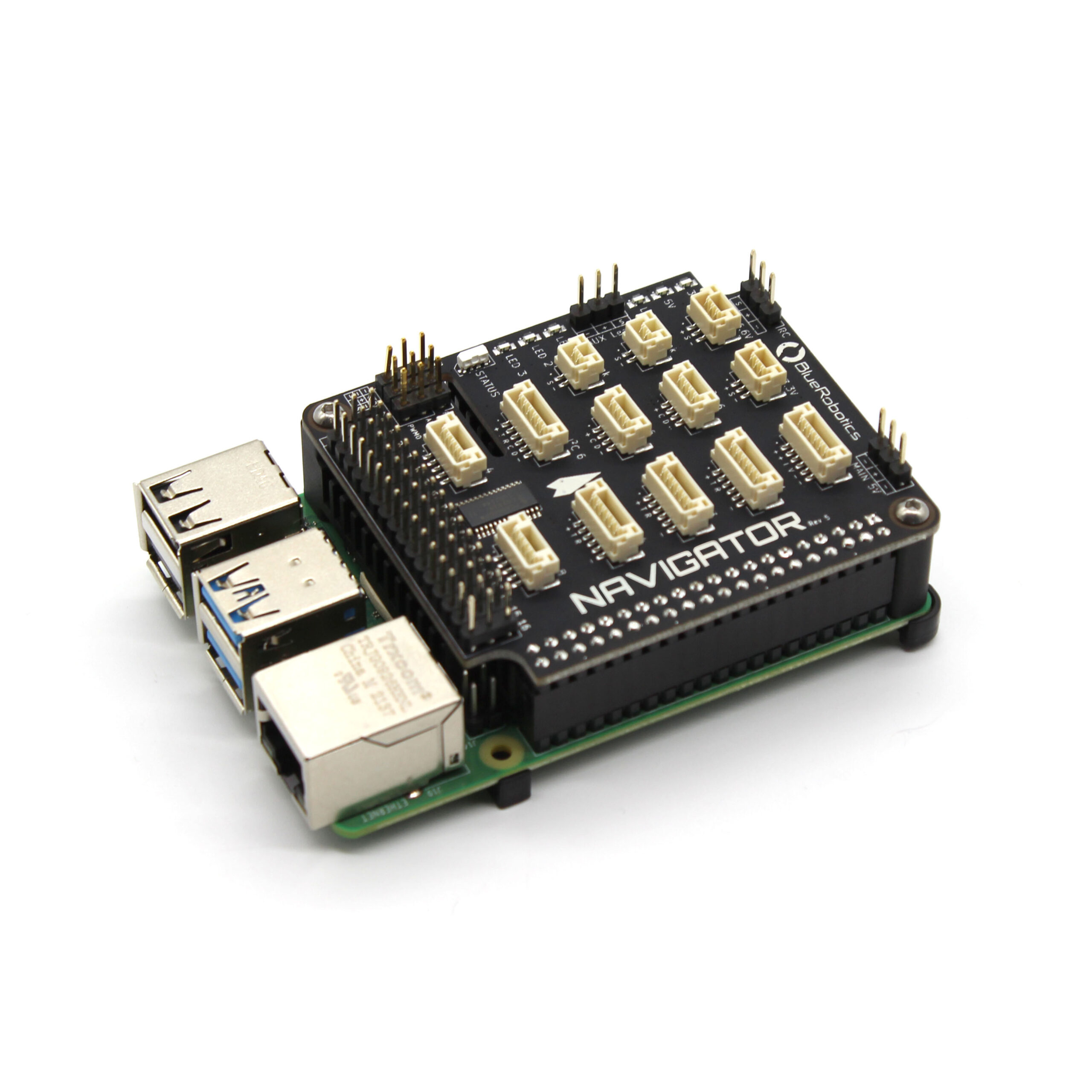
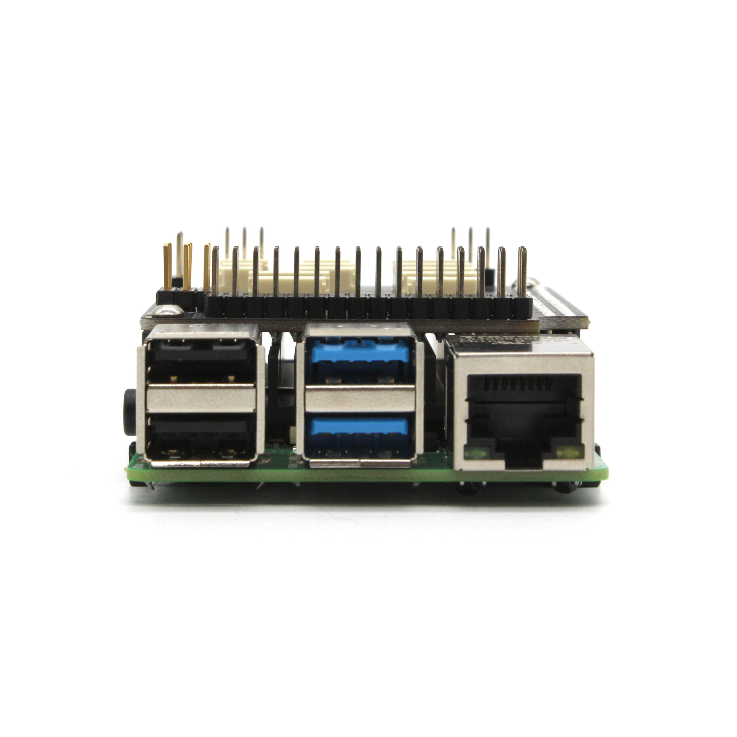
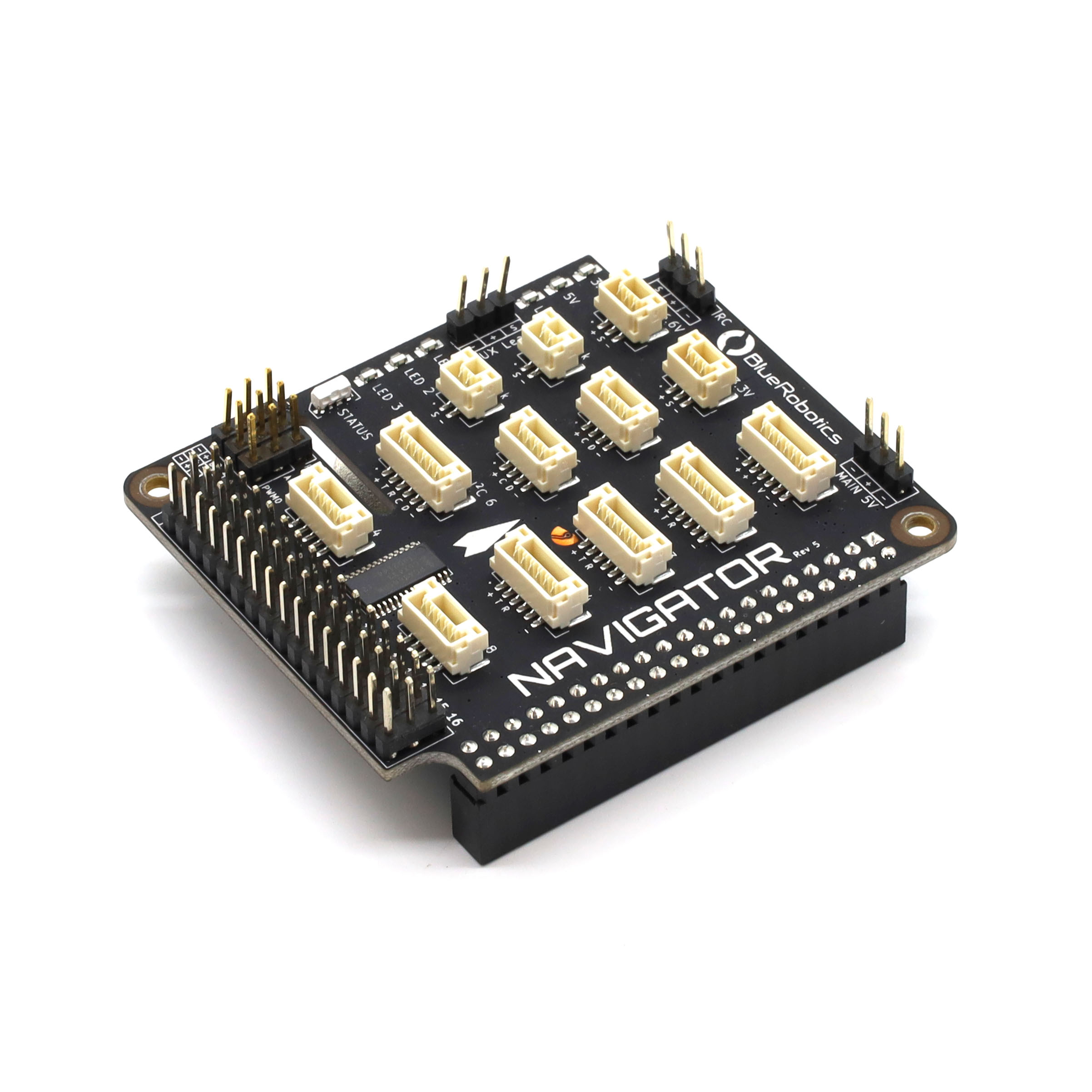
The Navigator is an ROV and robotics flight controller for the Raspberry Pi 4. It has an onboard IMU, compass, barometer, and ADC sensors as well as 16 PWM outputs and numerous serial and I2C expansion ports. The Navigator is used on the BlueROV2 and BlueBoat in conjunction with the BlueOS software, but can also be used for a wide range of robotics applications!

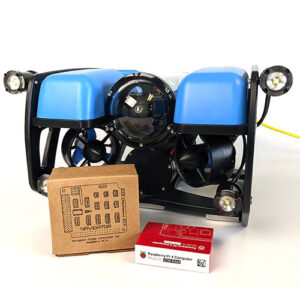
If you would like to upgrade your BlueROV2 with a Navigator Flight Controller, check out our Navigator Retrofit Guide.

SKU: BR-100367
HS Code: 8471.49.0000

Product Description

The Navigator is an expansion board that plugs into the Raspberry Pi 4 and turns it into a fully-featured flight controller, ready to power ROVs, USVs, drones, ground vehicles, and just about anything that moves!

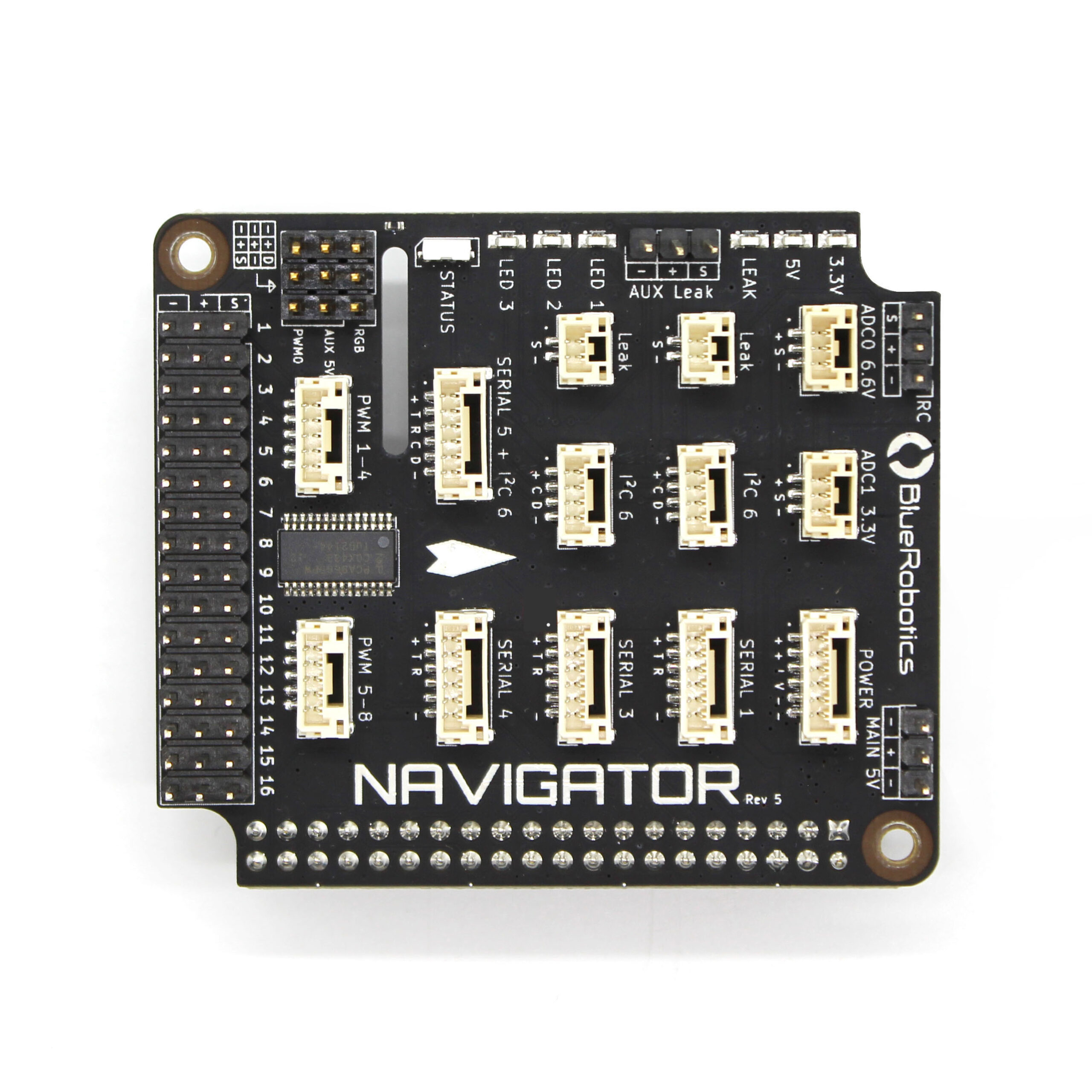
At its core, the Navigator is a collection of inputs and outputs. It has inputs from onboard sensors, outputs to servos or speed controllers, and expansions ports that can be connected to external devices.

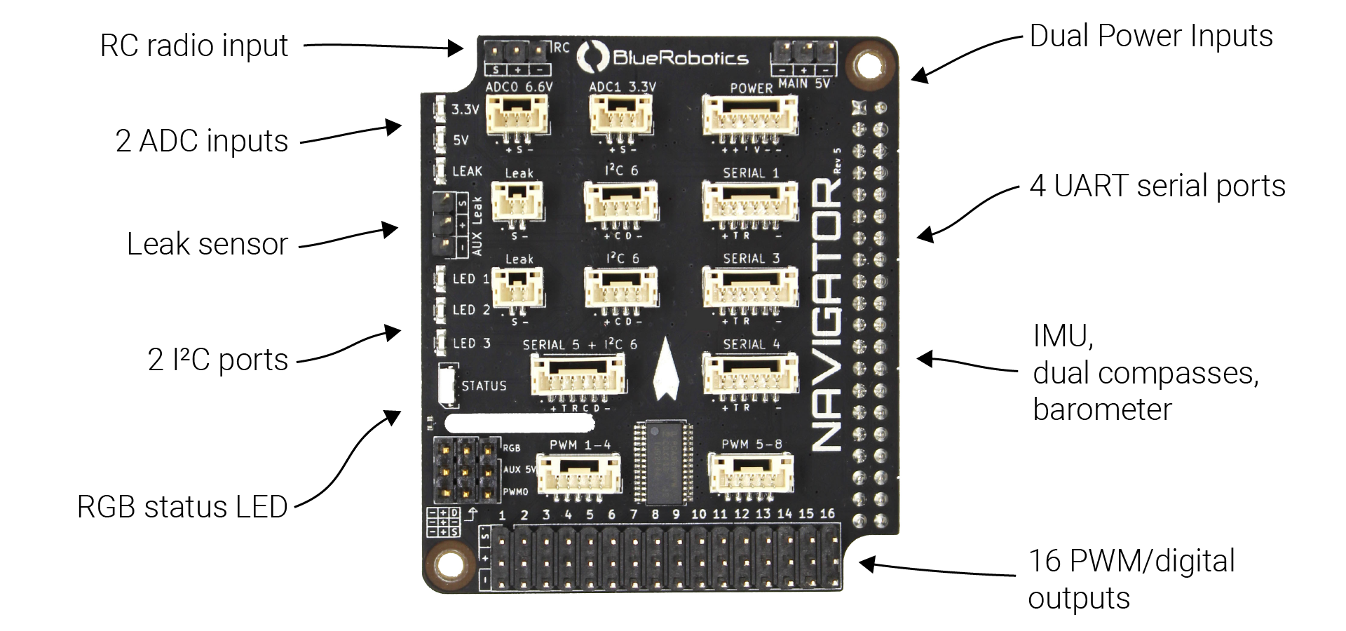
Onboard, the Navigator has:

  • 6-axis IMU with accelerometers and gyroscopes for orientation
  • Dual three-axis magnetometers for compass heading
  • Barometer for altitude in air
  • 16 servo PWM channel outputs
  • Current and voltage ADC inputs
  • Built-in leak detection for 2 probes
  • RC receiver input (SBUS)
  • RGB status LED
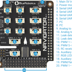
Navigator Flight Controller features.

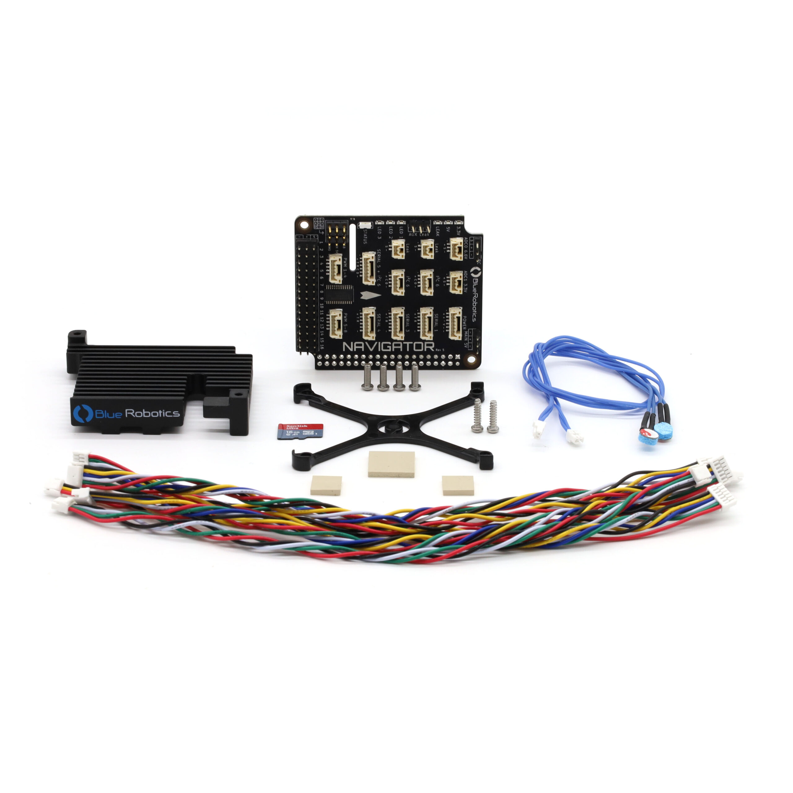
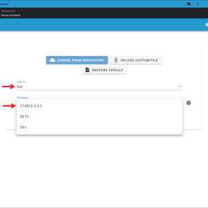
The Navigator kit ships with an SD card loaded with BlueOS, our new core operating software for ROVs, USVs, and other robotics. Built on top of Raspbian Linux, it provides a host of features including autopilot software management, video streaming, software updates, and user-defined extensions. It allows you to get started quickly with the Navigator and ArduPilot firmwares.

The Navigator schematic design is open source and available to help you maximize your usage of the Navigator.

Additionally, the Navigator has expansion connectors available, all of which follow the Blue Robotics Connector Standard and are compatible with most industry autopilot accessories. It has the following expansion ports:

  • 4 serial ports
  • 2 I2C ports
  • 2 16-bit analog-to-digital converter (ADC) ports
  • External LED port compatible with Neopixel RGB LEDs

In addition, the Navigator has a number of important features that are worth highlighting:

  • Dual power inputs with automatic power switching for redundancy
  • 3.3V logic on all ports
  • 5V tolerance on serial ports

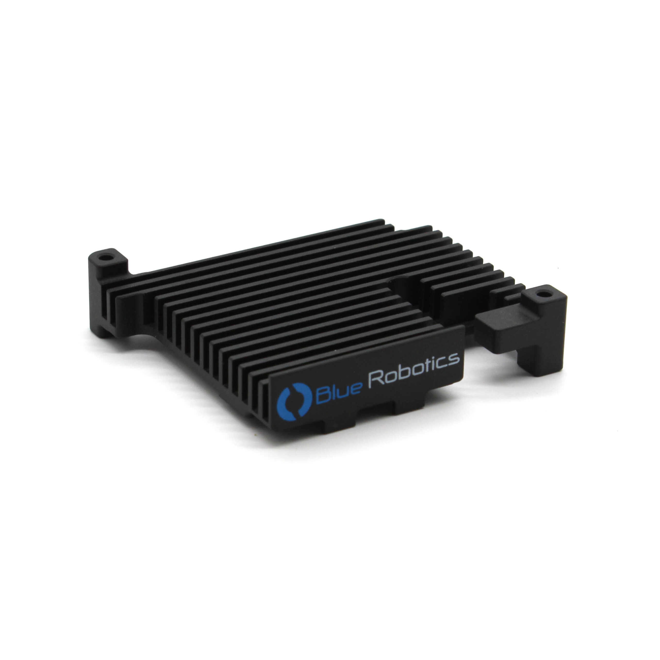
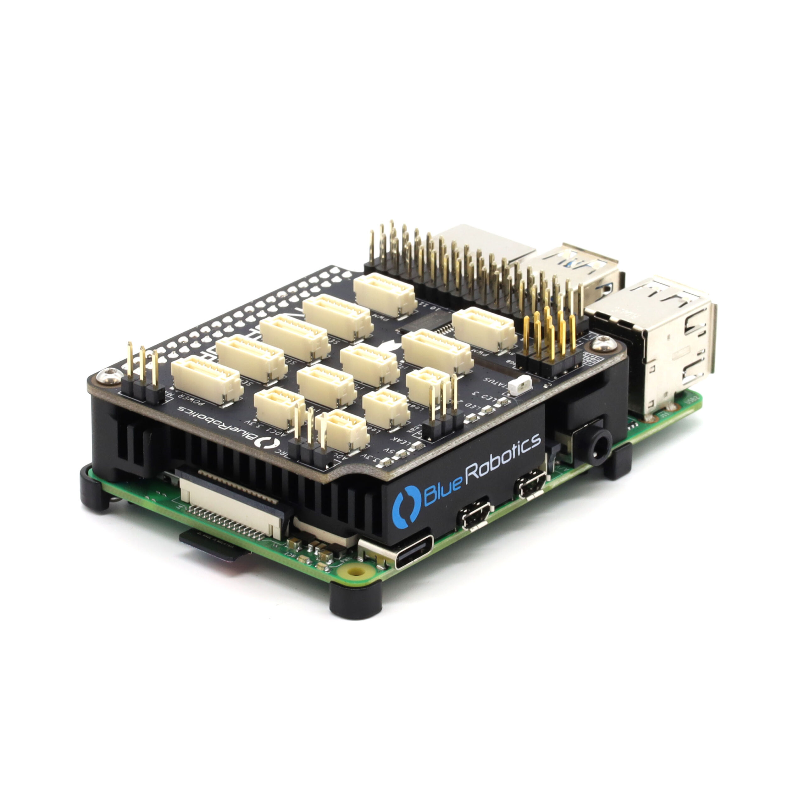
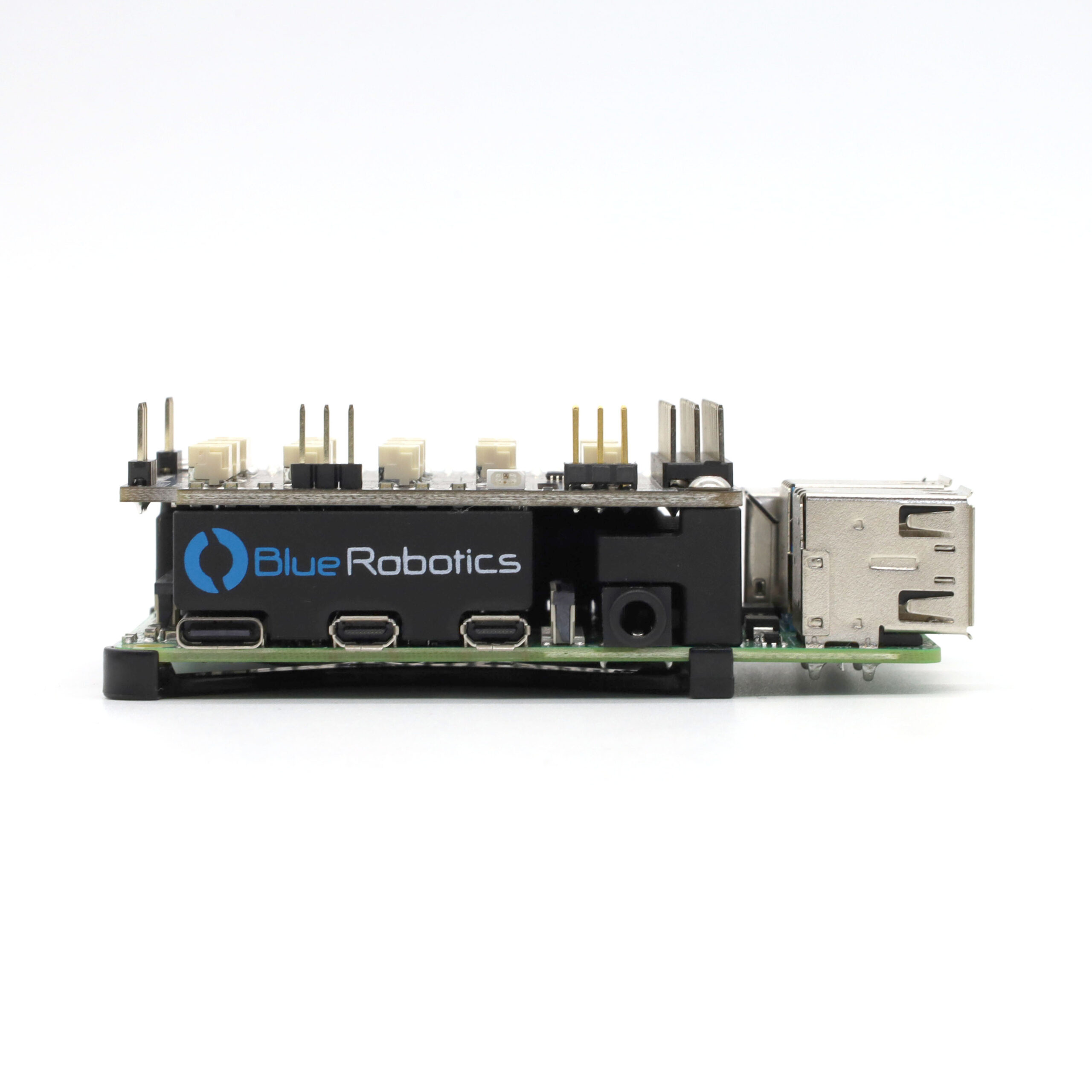
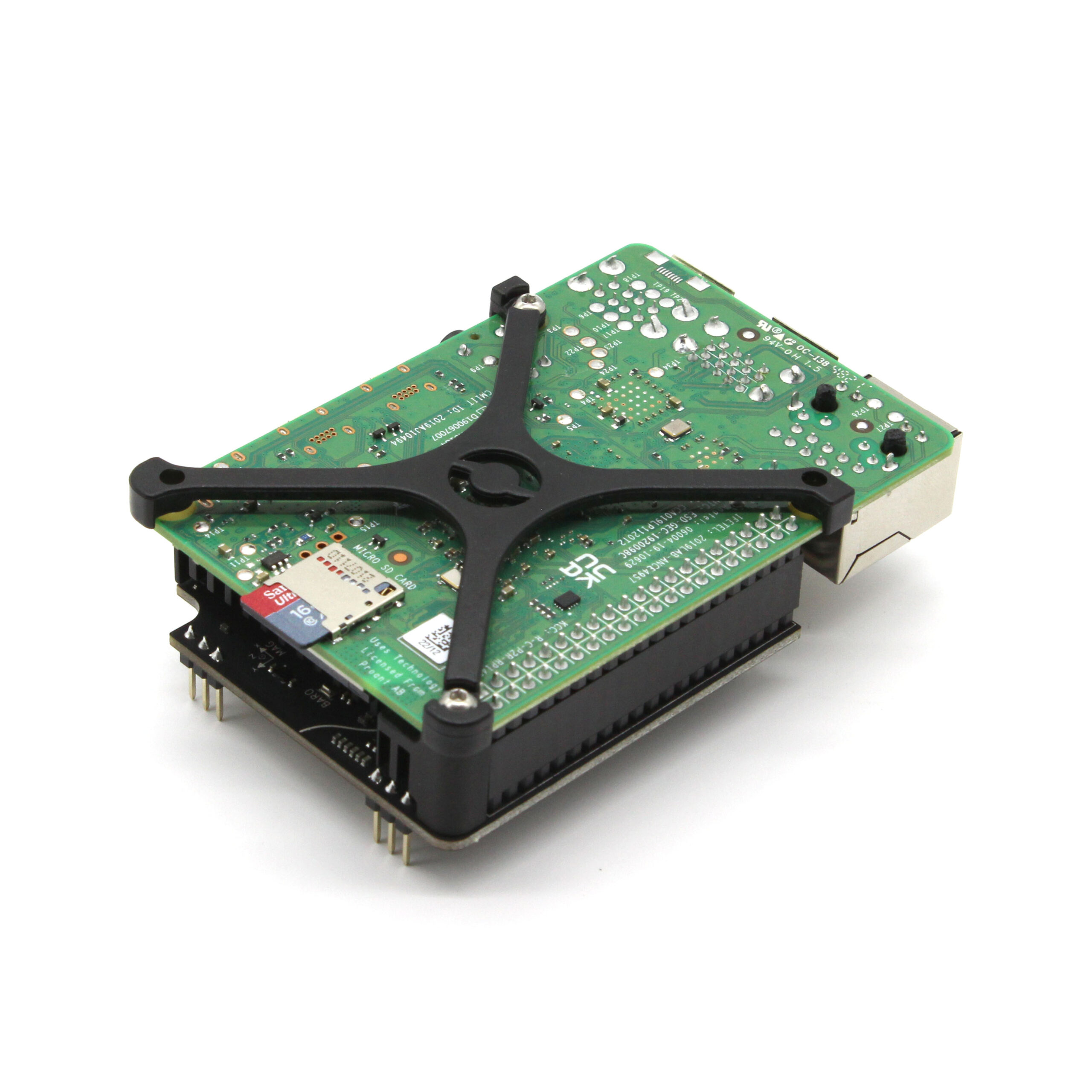
The Navigator comes with a custom designed aluminum heatsink that fits between the Navigator and Raspberry Pi and allows the Raspberry Pi to operate at high CPU usage in poorly cooled environments, like inside an enclosure. There’s a slot in the Navigator board that allows you to use the Raspberry Pi’s CSI camera connector.

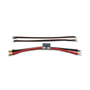
The Navigator kit also comes with a set of expansion cables for the serial, I2C, and ADC ports to allow you to connect your hardware quickly and easily.

The Navigator is technically not a Raspberry Pi “hat” because it does not meet all of the official requirements, however it works very similarly to a Raspberry Pi hat.
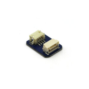
  • 1 x Navigator PCB
  • 1 x Navigator heatsink
  • 1 x Raspberry Pi mounting standoff
  • 1 x 128 GB microSD card with BlueOS
  • 3 x Thermal pads
  • 2 x 3-pin JST GH cable for accessories/expansion
  • 1 x 4-pin JST GH cable for accessories/expansion
  • 3 x 6-pin JST GH cable for accessories/expansion
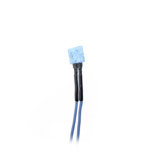
  • 2 x SOS leak probe, 12″ length
  • 4 x M2.5×8 button head cap screw
  • 2 x #3-28×3/8 mounting screw

Specifications

ParameterValue
Electrical
Supply Voltage5–5.35 V (Main input)
5–5.35 V (Power module connector)
5–5.35 V (Aux input)
Current Draw5 mA (Idle)
150 mA (Typical)
200 mA (Max)
Logic Level Voltage3.3 V (5 V input tolerant)
PWM Signal Voltage Level3.3 V
Maximum Power Delivery to Raspberry Pi and Peripherals4 A continuous, 4.5 A peak
Performance
Pressure Sensor Measurement Range300–1100 mbar-900–9000 m
Pressure Sensor Relative Accuracy0.12 mbar1 m
Pressure Sensor Absolute Accuracy1 mbar8 m
Pressure Sensor Resolution0.0016 mbar1.5 cm
PWM Accuracy±0.5 µs
(@ 50, 100, 200, 250, 400, 500 Hz)
PWM Resolution1 μs @ 250 Hz
ADC Resolution16 bits
(14.4 bits effective)
On-Board Sensors
6-Axis IMUICM-20602
3-Axis Digital MagnetometerMMC5983
3-Axis Electronic CompassAK09915
Digital Pressure Sensor (Barometer)BMP280
Analog to Digital Converter (ADC)ADS1115
On-Board ICs
16 Channel PWM Module with External OscillatorPCA9685
Logic Voltage TranslatorTXS0102
Power Mux & Ideal DiodeTPS2121
Additional ICsSerial inverter for RC receivers
3.3 V to 5 V translation for RGB neopixel LEDs
4KB EEPROM
Ports/Interfaces¹3 x Serial UART (no flow control)
2 x I2C
1 x UART + I2C
1 x ADC (3.3 V)
1 x ADC (6.6 V)
1 x RC receiver
1 x Power module connector
16 Channel PWM out
2 x SOS leak probe connectors
1 x Auxiliary SOS board connector
1 x PWM out (fan)
1 x RGB LED header
3 x User definable LEDs
RC Receiver CompatibilitySBUS, Crossfire, IBUS
(inverted/non-inverted serial receivers)
Software Development Libraries Navigator Python / C++
Navigator Rust
ComplianceRoHS (lead free)
Physical
Operating Temperature-40°C to 60°C-40°F to 140°F
Storage Temperature-40°C to 85°C-40°F to 185°F
Weight26 g
Dimensions65 x 56 mm
Screw Hole Spacing58 x 49 mm
Screw Hole Diameter2.75 mm
Heat Sink Weight30 g
Heat Sink Dimensions65 x 56 x 14 mm
Heat Sink MaterialAnodized 6061-T6 Aluminum
Heat Sink Mounting HolesM2.5x0.45
Thermal Pad MaterialSilicone
Accessory Cable Length200 mm
Accessory Cable Wire TypeUL1571 28AWG PVC Insulation
¹ All connectors follow the Blue Robotics Connector Standard.

Pinouts

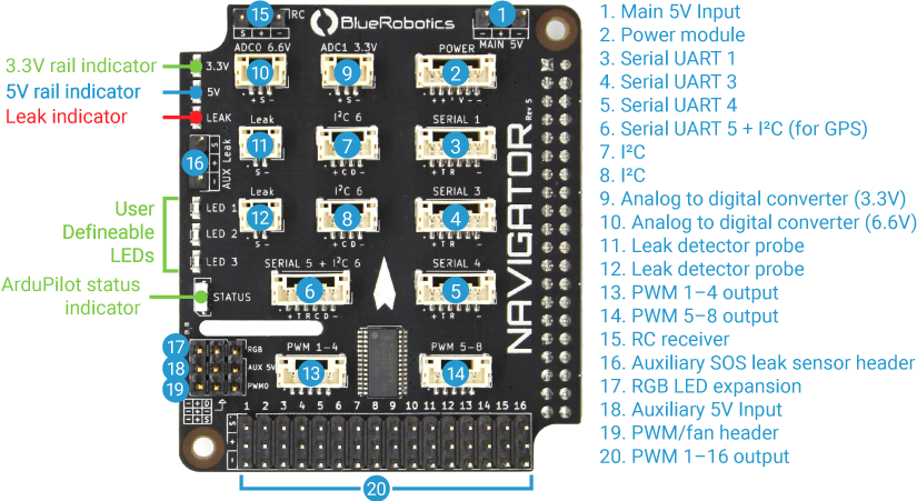
MAIN 5V
Connector Pinout1 - GND
2 - Vin
3 - GND
GND
5 V Supply
GND
Connector Type3 position 0.1″ pitch male header pins
Mating Connector3 position 0.1″ pitch female header
POWER
Connector Pinout1 - Vin
2 - Vin
3 - Current sense
4 - Voltage sense
5 - GND
6 - GND
5 V Supply
5 V Supply
3.3 V
3.3 V
GND
GND
JST GH Connector TypeBM06B-GHS-TBT(LF)(SN)(N)
Mating JST GH Plug and Crimp PinsGHR-06V-S (housing)
SSHL-002T-P0.2 (pin)
AUX 5V
Connector Pinout1 - GND
2 - Vin
3 - GND
GND
5 V Auxiliary supply
GND
Connector Type3 position 0.1″ pitch male header pins
Mating Connector3 position 0.1″ pitch female header
SERIAL 1, SERIAL 3, SERIAL 4
Blue Robotics Connector Standard Reference
Connector Pinout1 - VCC
2 - TX (out)
3 - RX (in)
4 - Empty
5 - Empty
6 - GND
5 V
3.3 V
3.3 V


GND
InterfaceUART
Serial 1 Path/dev/ttyS0
Serial 3 Path/dev/ttyAMA1
Serial 4 Path/dev/ttyAMA2
Serial 1 Baud Rate1200 Bd–2 MBd
Serial 3, Serial 4 Baud Rate1200 Bd–3 MBd
Maximum Power1 A
JST GH Connector TypeBM06B-GHS-TBT(LF)(SN)(N)
Mating JST GH Plug and Crimp PinsGHR-06V-S (housing)
SSHL-002T-P0.2 (pin)
I2C 6
Blue Robotics Connector Standard Reference
Connector Pinout1 - VCC
2 - SCL
3 - SDA
4 - GND
5 V
3.3 V
3.3 V
GND
InterfaceI2C
Path/dev/i2c-6
Baud Rate10 kHz–1 MHz
Maximum Power1 A
JST GH Connector TypeBM04B-GHS-TBT(LF)(SN)(N)
Mating JST GH Plug and Crimp PinsGHR-04V-S (housing)
SSHL-002T-P0.2 (pin)
SERIAL 5 + I2C 6
Connector Pinout1 - VCC
2 - TX (UART out)
3 - RX (UART in)
4 - SCL (I2C)
5 - SDA (I2C)
6 - GND
5 V
3.3 V
3.3 V
3.3 V
3.3 V
GND
InterfaceUART + I2C
UART Path/dev/ttyAMA3
I2C Path/dev/i2c-6
UART Baud Rate1200 Bd–3 MBd
I2C Baud Rate10 kHz–1 MHz
Maximum Power1 A
JST GH Connector TypeBM06B-GHS-TBT(LF)(SN)(N)
Mating JST GH Plug and Crimp PinsGHR-06V-S (housing)
SSHL-002T-P0.2 (pin)
PWM 1–4
Connector Pinout1 - PWM01
2 - PWM02
3 - PWM03
4 - PWM04
5 - GND
3.3 V
3.3 V
3.3 V
3.3 V
GND
Max Signal Current Draw15 mA
JST GH Connector TypeBM05B-GHS-TBT(LF)(SN)(N)
Mating JST GH Plug and Crimp PinsGHR-05V-S (housing)
SSHL-002T-P0.2 (pin)
PWM 5–8
Connector Pinout1 - PWM05
2 - PWM06
3 - PWM07
4 - PWM08
5 - GND
3.3 V
3.3 V
3.3 V
3.3 V
GND
Max Signal Current Draw15 mA
JST GH Connector TypeBM05B-GHS-TBT(LF)(SN)(N)
Mating JST GH Plug and Crimp PinsGHR-05V-S (housing)
SSHL-002T-P0.2 (pin)
PWM 1–16
Connector Pinout1 - PWM Signal
2 - V (Aux)
3 - GND
3.3 V
V (Aux)
GND
Max Signal Current Draw15 mA
Connector Type3 position 0.1″ pitch male header pins
Mating Connector3 position 0.1″ pitch female header
RC
Connector Pinout1 - Serial
2 - VCC
3 - GND
3.3 V
5 V
GND
Connector Type3 position 0.1″ pitch male header pins
Mating Connector3 position 0.1″ pitch female header
ADC0 6.6V
Connector Pinout1 - VCC
2 - Signal
3 - GND
5 V
0–6.6 V Analog input
GND
JST GH Connector TypeBM03B-GHS-TBT(LF)(SN)(N)
Mating JST GH Plug and Crimp PinsGHR-03V-S (housing)
SSHL-002T-P0.2 (pin)
ADC1 3.3V
Connector Pinout1 - VCC
2 - Signal
3 - GND
5 V
0–3.3 V Analog input
GND
JST GH Connector TypeBM03B-GHS-TBT(LF)(SN)(N)
Mating JST GH Plug and Crimp PinsGHR-03V-S (housing)
SSHL-002T-P0.2 (pin)
Leak
Connector Pinout1 - Signal
2 - GND
5 V Pull-up
GND
JST GH Connector TypeBM02B-GHS-TBT(LF)(SN)(N)
Mating JST GH Plug and Crimp PinsGHR-02V-S (housing)
SSHL-002T-P0.2 (pin)
AUX Leak
Connector Pinout1 - Signal
2 - VCC
3 - GND
5 V
5 V
GND
Connector Type3 position 0.1″ pitch male header pins
Mating Connector3 position 0.1″ pitch female header
RGB
Connector Pinout1 - Data
2 - V (Aux)
3 - GND
5 V
V (Aux)
GND
Connector Type3 position 0.1″ pitch male header pins
Mating Connector3 position 0.1″ pitch female header
PWM0
Connector Pinout1 - PWM0
2 - V (Aux)
3 - GND
3.3 V
V (Aux)
GND
Connector Type3 position 0.1″ pitch male header pins
Mating Connector3 position 0.1″ pitch female header

3D Models

NAVIGATOR-PCB-R1 (.zip)

NAVIGATOR-STACK (.zip)

Documents

NAVIGATOR-PCB-SCHEMATIC (.pdf)

All sensor and IC datasheets are linked in technical details.

Revision History

2 October 2024

  • SD card updated to BlueOS 1.3.1

15 May 2024

  • SD card upgraded from 16 GB to 128 GB

23 January 2024

  • SOS probe tips changed to square

25 April 2023

  • SKU changed from NAVIGATOR-KIT-R1 to BR-100367

1 June 2022

  • NAVIGATOR-KIT-R1 - Initial release

Quick Start

Guides

Navigator Hardware Setup
Learn how to assemble the Navigator kit and connect your vehicle hardware.
Navigator Software Setup
Learn how to install ArduPilot firmware using BlueOS and configure your vehicle using ground control station software.
Navigator Retrofit Guide
This guide will show you how to replace the Pixhawk autopilot with a new Navigator Flight Controller in your BlueROV2.
Connecting Your Device with Navigator and BlueOS
Get things connected to your BlueOS powered vehicle! Whether Serial, I2C, Ethernet or USB, collecting data for your application is possible!
Navigator Developer Guide
Access the Navigator hardware directly using the Navigator Library!

Relevant Forum Categories

Blue Robotics Forums - Flight Controllers

Featured Forum Posts