
Watertight Enclosure (WTE) User Guide
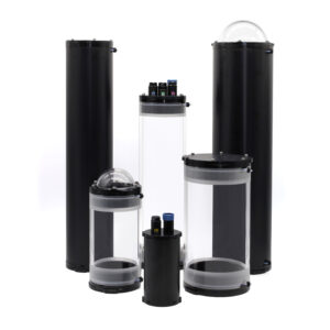
Our second-generation series of Watertight Enclosures are completely configurable with a variety of tube and end cap options making them a perfect fit for a wide range of applications. This guide will show you how to assemble and use your Watertight Enclosure.
General Information and Safety
Using a Pressure Relief Valve or Vent
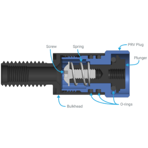
Every Watertight Enclosure should have a vent or Pressure Relief Valve (PRV) installed. This allows the enclosure to release pressure while being opened or closed. It is strongly recommended to use a Pressure Relief Valve for safety when using the enclosure with a locking cord. The locking cord is used to secure the flanges to the tube, preventing accidental detachment. However, this additional security means that if an excessive amount of pressure builds up inside the tube, it can create an unsafe situation. The Pressure Relief Valve is designed to automatically release any internal pressure in the enclosure in a safe manner.
Pressure Relief Valve Installation and Usage
WTE Vent Assembly Guide
Bulkhead Sizes
The Watertight Enclosure end caps are available in different hole configurations with M10-size holes, M14-size holes, or both. Be sure to select the correct end cap hole configuration and bulkhead sizes for your application.
M10 Holes
Most Blue Robotics products with preinstalled bulkhead penetrators use M10-size bulkheads and require an M10 end cap hole.
M10 bulkheads can be installed using the M10 size Bulkhead Wrench or a 16 mm wrench.
M14 Holes
M14 end cap holes support larger M14 size bulkhead penetrators. Currently, the T500 Thruster and the 9.5MM size WLP are the only Blue Robotics products that use an M14 size bulkhead.
M14 bulkheads can be installed using the M14 size Bulkhead Wrench or a 20 mm wrench.
Bulkhead Adapters
WetLink Bulkhead Adapters can be used to install a bulkhead into an end cap hole that is too large.
Long-term Submersion
For long-term submersion of greater than two weeks, we recommend using aluminum Watertight Enclosure components only. The depth ratings for cast acrylic components are applicable only for short-term submersions lasting less than two weeks.
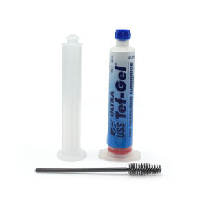
During long-term submersion in saltwater, the stainless steel hardware may start to corrode the aluminum enclosure material through galvanic corrosion. Galvanic corrosion can be prevented by using Tef-Gel or a sacrificial anode, you can find more information in our Fighting Galvanic Corrosion with Zinc and Tef-Gel guide.
Parts and Tools for Assembly
-
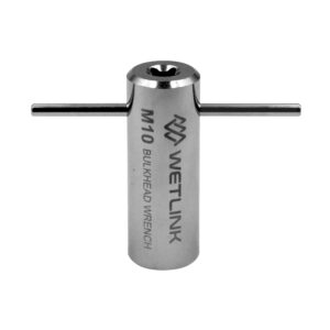
WetLink Bulkhead Wrench
For use with M06, M10 or M14 bulkheadsPrice range: $17.00 through $22.00 -
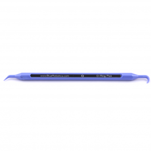
O-Ring Pick
Remove O-rings without damaging the O-ring gland$4.00 -
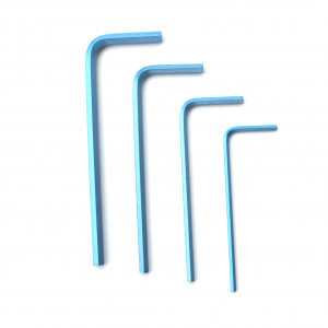
Hex Key Set
Commonly used on the BlueROV2 and other products$7.00 -
Molykote 111
For lubricating O-rings and other sealsPrice range: $4.00 through $32.00
Hex driver sizes:
- 1.5 mm hex for 2″ series enclosures
- 1.5 mm and 2.5 mm hex for 3″, 4″, 5″, 6″ and 8″ series enclosures
Assembling the Enclosure
1. Inspect the inner ends of the enclosure tube, the O-ring grooves on the flanges, and the end caps to make sure they are free of scratches, damage, or dust/debris.
- Some aluminum parts may have small discolored spots in the anodization, this is normal and won’t cause problems.
2. Apply an even layer of silicone grease (Molykote 111) to both inner ends of the tube.
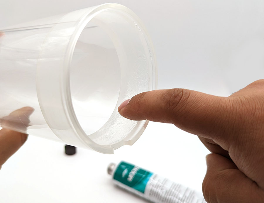
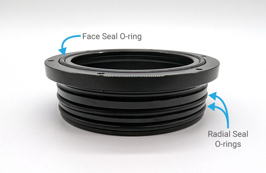
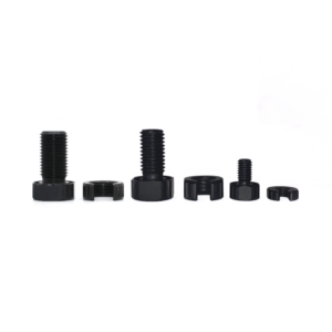
3. Apply a thin, even layer of silicone grease to the flange/flange cap O-rings and install them onto the flange or flange cap:
- Regular flanges use three O-rings: two radial seal O-rings and one face seal O-ring.
- 2″ series flange caps use only two radial seal O-rings.
The 2″, 3″, 5″, 6″, and 8″ series flanges use different O-ring sizes for the face and radial seals.
- Use the single smaller O-ring for the face seal.
- Use the two larger O-rings for the radial seals.
- For 4″ series flanges, all the O-rings are the same size.
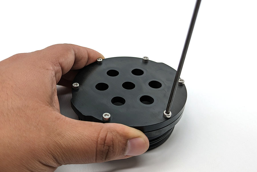
4. Install the end cap or dome onto the flange using the socket cap screws and a hex driver. Do not use thread locker on acrylic end caps or domes. Install all the screws loosely first then fully tighten the screws in a criss-cross (star) pattern. Skip this step if you have a 2″ series flange cap.
Proceed to the next sections.
Installing Optional RAILS
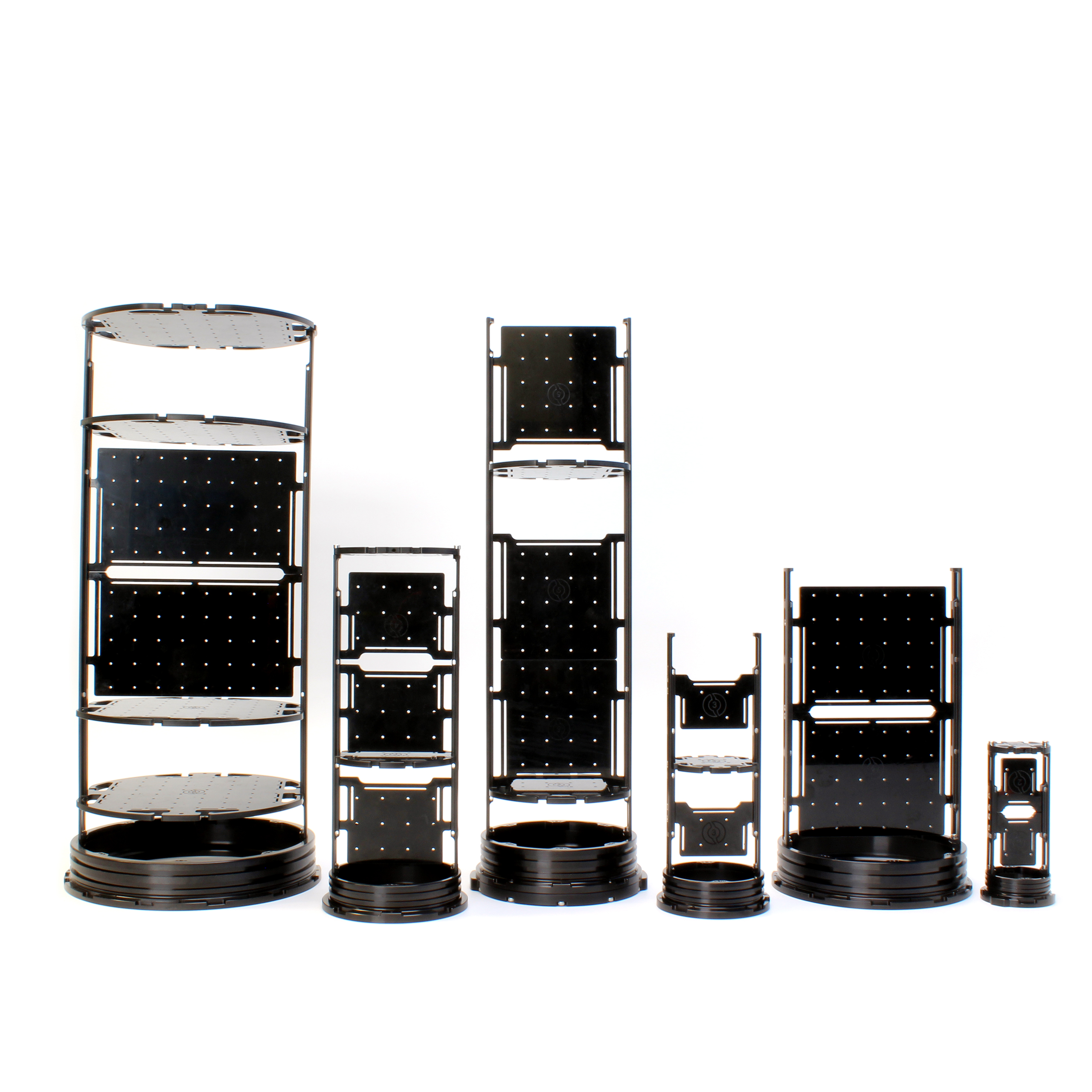
RAILS is a modular electronics tray system that makes it easy to mount hardware and electronics in a Watertight Enclosure.
If you have purchased RAILS for your enclosure, head over to the user guide for installation instructions. If you’re not using RAILS, go on to the ‘Installing a Bulkhead’ section.
Watertight Enclosure RAILS User Guide
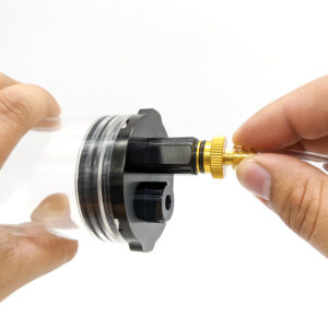
Installing a Bulkhead
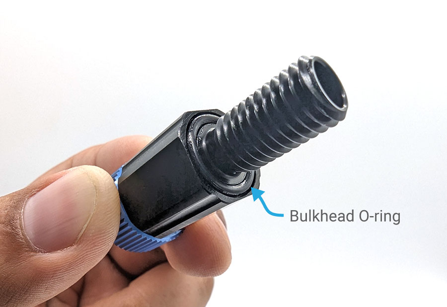
1. Inspect the bulkhead O-ring to make sure it is not dirty or damaged.
2. Lubricate the bulkhead O-ring with a thin layer of silicone grease and install it in the groove on the underside of the bulkhead.
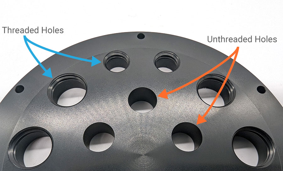
End cap holes can be either threaded or unthreaded.
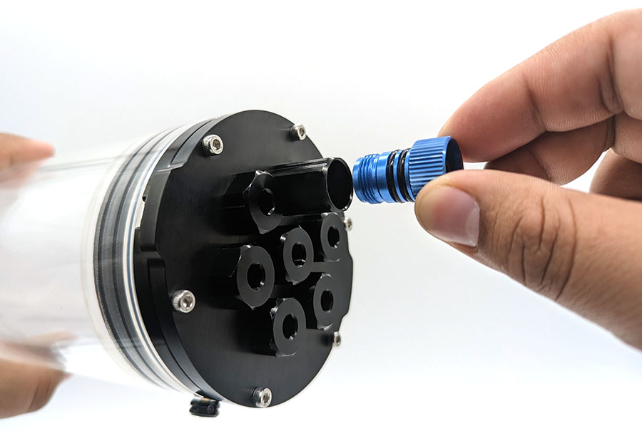
Installing in an Unthreaded Hole
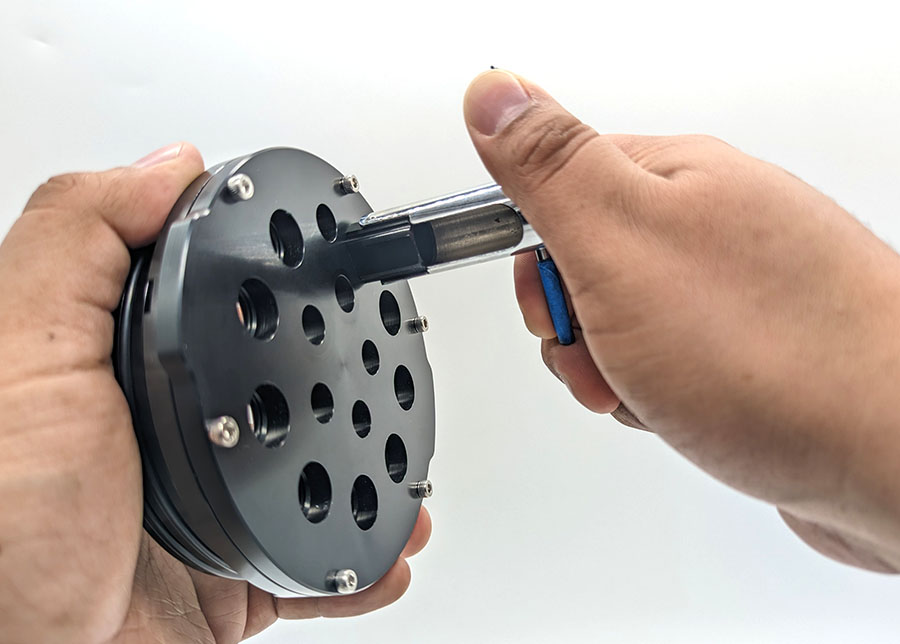
1. Insert the bulkhead through the hole and fasten a penetrator nut on the other side. Tighten the nut and bulkhead by hand until the bulkhead is held in place.
2. Use the Bulkhead Wrench to fully tighten the bulkhead. The Bulkhead Wrench can be used to tighten either the bulkhead or the nut. The bulkhead should no longer rotate in the hole when installed properly. If the bulkhead cannot be loosened using your fingers, it is tight enough.
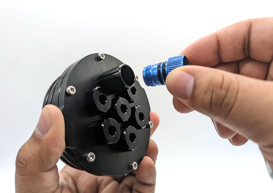
Installing in a Threaded Hole
1. Thread the bulkhead into the threaded hole until it is finger-tight. Do not use a penetrator nut in the back of the bulkhead.
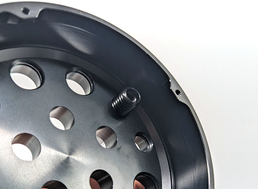
No penetrator nut used.
2. Use the Bulkhead Wrench to fully tighten the bulkhead. If the bulkhead cannot be loosened using your fingers, it is tight enough.
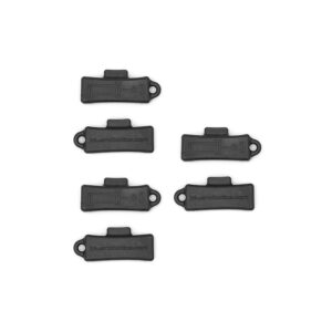
Using Blank Penetrators
After installing all of your bulkheads, seal any unused holes in the end cap with a penetrator blank.
Finishing Assembly
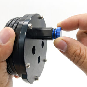
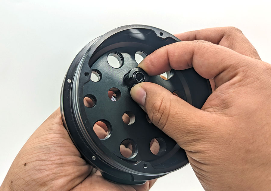
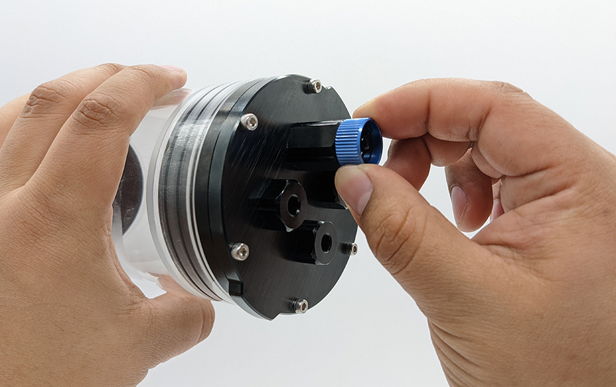
1. Remove the plug from the Pressure Relief Valve or vent.
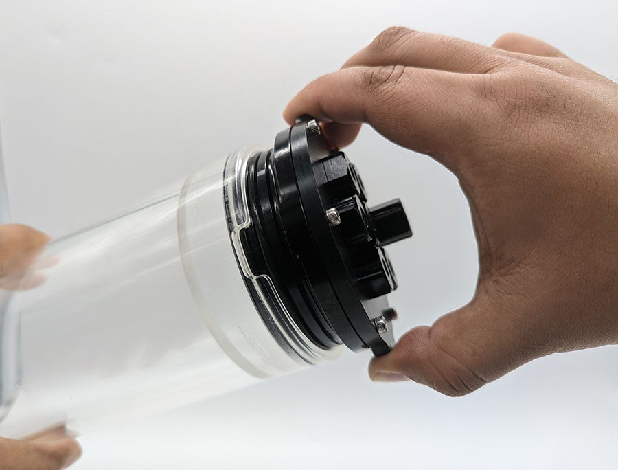
2. Install the flanges onto the tube. The flanges have a rotation locking tab that must sit in the slot in the tube to fully seat the flange.
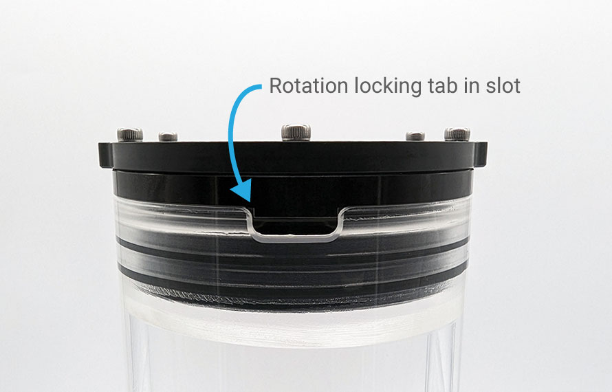
Rotation locking tab in slot.
2. Reinstall the Pressure Relief Valve or vent plug back in the bulkhead to seal it.
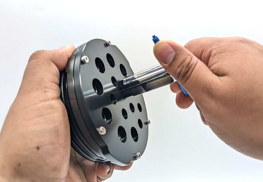
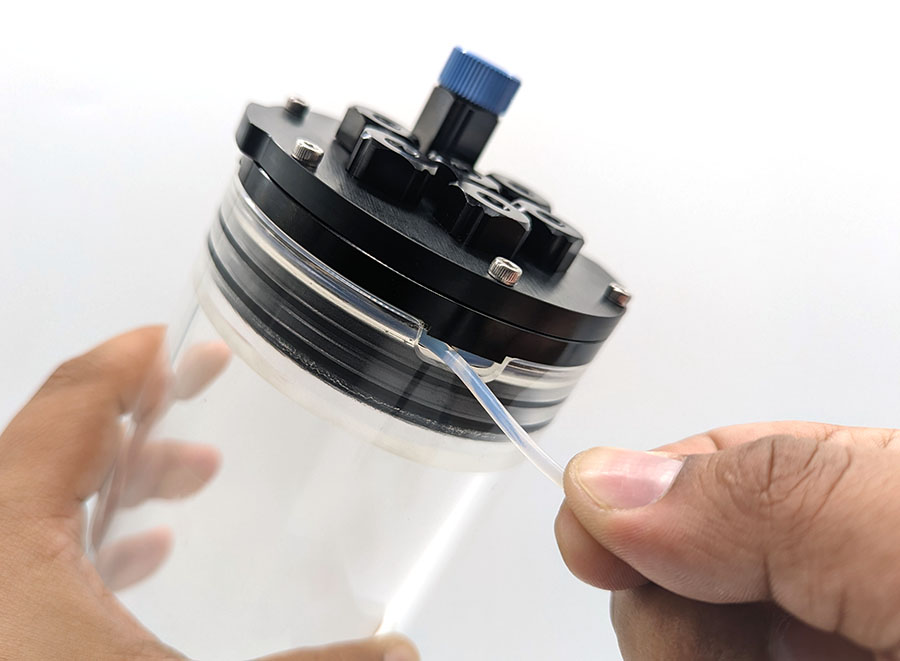
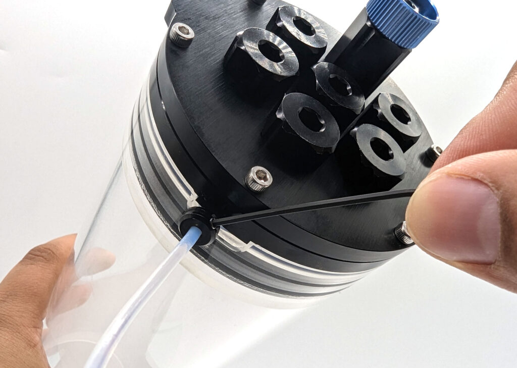
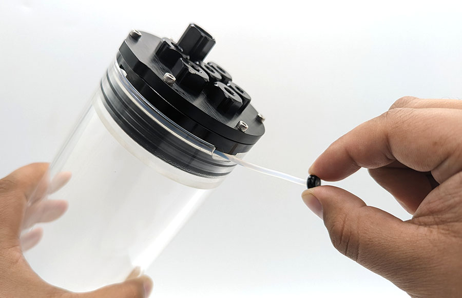
3. Insert the plastic locking cord through the slot and feed it through the locking cord channel. Push it all the way in until it reaches around to the other side. If it is difficult to push in the locking cord, it usually means the flange is not fully seated in the tube. Make sure the tab is aligned in the slot and the flange is pushed all the way in.
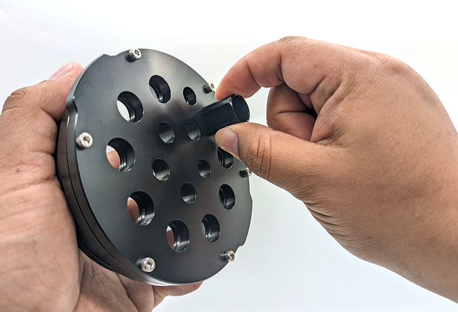
4. Install the locking cord handle onto the locking cord so it sits close against the tube. Tighten the set screw using a 1.5 mm hex driver.
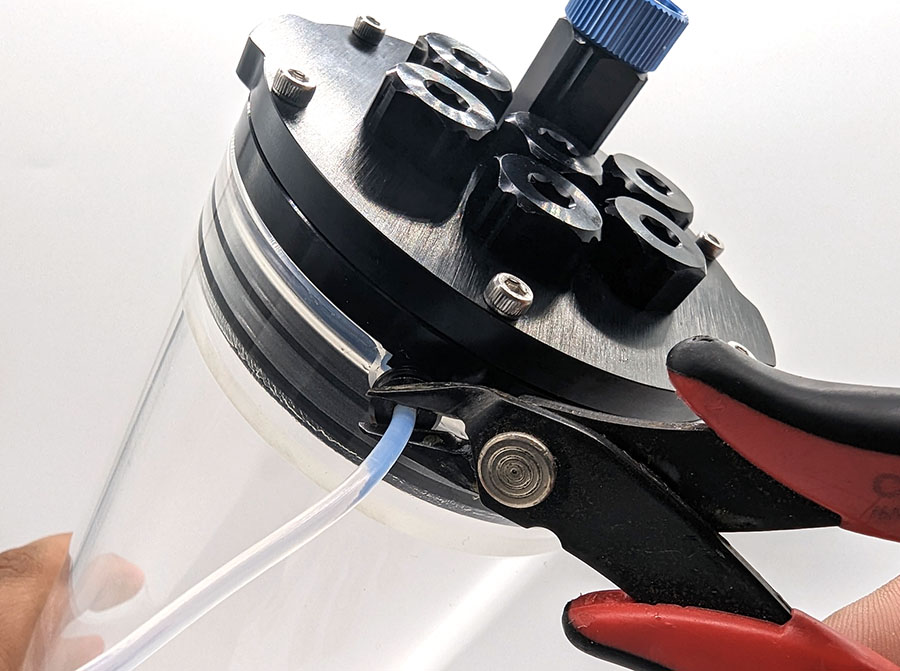
5. Trim any excess locking cord.
Vacuum Testing an Enclosure
We strongly recommend performing a vacuum test on all newly assembled Watertight Enclosures or whenever you install or remove a bulkhead. Check out the guide below for instructions on how to use the hand-operated vacuum pump kit to test your enclosures.
Using the Vacuum Plug and Hand Pump
Opening and Closing an Enclosure
Opening
1. Remove the vent or Pressure Relief Valve plug from the bulkhead.
2. Pull out the locking cord.
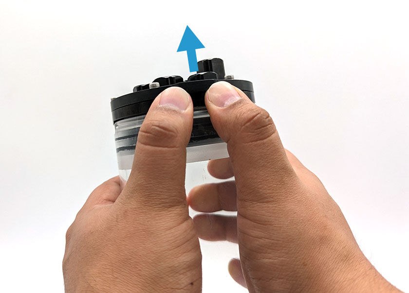
3. Remove the flange from the tube.
If removing the flange from the tube is difficult, try pushing the flange up from the end cap tabs. Alternate pushing up from the tab on each side of the end cap until the flange is off.
You can also use the Watertight Enclosure Pry Tool. Insert the pry tool into the locking cord slot or the pry slots then give it a twist to separate the flange from the tube.
Closing
1. Make sure the vent or Pressure Relief Valve plug is not installed in the bulkhead.
2. Insert the flange fully into the tube. Make sure the rotation locking tab on the flange sits in the slot in the tube.
3. Insert the locking cord through the slot and push it all the way in to lock the flange to the tube.
4. Reinstall the plug in the bulkhead to seal the enclosure.
Removing a Bulkhead
Use a Bulkhead Wrench to turn the bulkhead or nut counterclockwise until it is loose enough to remove by hand.
Maintenance
- Check that O-rings are not dirty or damaged after servicing the enclosure. Replacement O-ring sets can be found here.
- Relubricate the inner edge of the tube and the radial seal O-rings with silicone grease if the flanges become difficult to remove.
- Relubricate the PRV or vent plug O-rings with silicone grease if it becomes difficult to remove.
- Only use a microfiber cloth to clean acrylic components to avoid scratching. NEVER use alcohol or other solvents to clean acrylic parts.
O-ring Sizes
The O-ring sizes for each flange are provided below for reference. Replacement O-ring sets are available here.
| Series Diameter | Face Seal O-ring | Radial Seal O-ring | Material | Hardness |
|---|---|---|---|---|
| 50 mm (2") | AS568-030 | AS568-031 | Buna-N | 70A |
| 75 mm (3") | AS568-148 | AS568-150 | Buna-N | 70A |
| 100 mm (4") | AS568-154 | AS568-154 | Buna-N | 70A |
| 125 mm (5") | AS568-157 | AS568-248 | Buna-N | 70A |
| 150 mm (6") | AS568-162 | AS568-255 | Buna-N | 70A |
| 200 mm (8") | AS568-170 | AS568-265 | Buna-N | 70A |
Customization
Drilling holes
The acrylic and aluminum end caps can be drilled to make your own custom hole configuration. Use a 10 mm drill bit to make holes for M10 bulkheads or a 14 mm drill bit for M14 bulkheads.
Installing Micro Circular Wet-Mateable Connectors
The standard thread for most Subconn and Seacon type Micro Circular connectors is 7/16″-20. The M10 end cap holes are the ideal size to be tapped with a 7/16″-20 tap to make the proper threads. Before tapping, make sure the end cap you are using is thick enough to make enough threads. For end caps that are too thin, you can just use a 7/16″ drill bit to drill out the hole and install the connector using a nut instead.
Custom End Caps
One of the coolest things about the modular design of the Watertight Enclosures is that it’s compatible with all sort of end cap sizes and shapes. We provide a variety of end cap options but we encourage you to design your own to perfectly suit your application. The 3D files provided on the product page, as well as the DXF files below, will give you a good starting point for your design. You’ll need access to either 3D modeling software like SolidWorks or AutoCAD or 2D drawing software like Adobe Illustrator, Inkscape, and others. Once you have a design, you can cut the parts yourself if you have a laser cutter or use an online service. We have frequently used Pololu Laser Cutting with great results.
The thicknesses and depth ratings for all of our end caps are provided in the technical details section for reference when creating your design. If you need to design for a particular depth rating, we recommend using Under Pressure software.
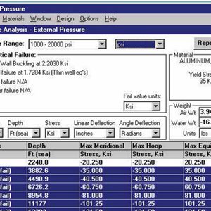
Under Pressure – Pressure Vessel Calculator
Feedback
We’re always trying to improve our documentation, instructions, software, and user experience. If you’d like to leave feedback about how we can make this guide better, let us know here.