
Thruster User Guide
Introduction
The T200 and T500 are underwater thrusters designed to be rugged, powerful, and flexible in many applications like high-power ROVs, surface vessels, AUVs, as well as human-carrying applications like kayaks. This guide will show you how to operate, service, and troubleshoot your T200 or T500 thruster.
Important Safety Notes
Thruster Overview
The following is some basic information to help you get familiar with the T200 and T500 thrusters.
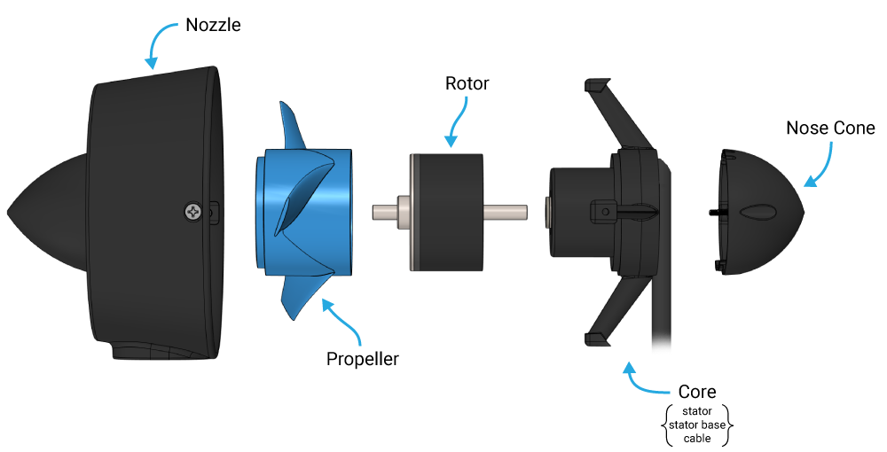
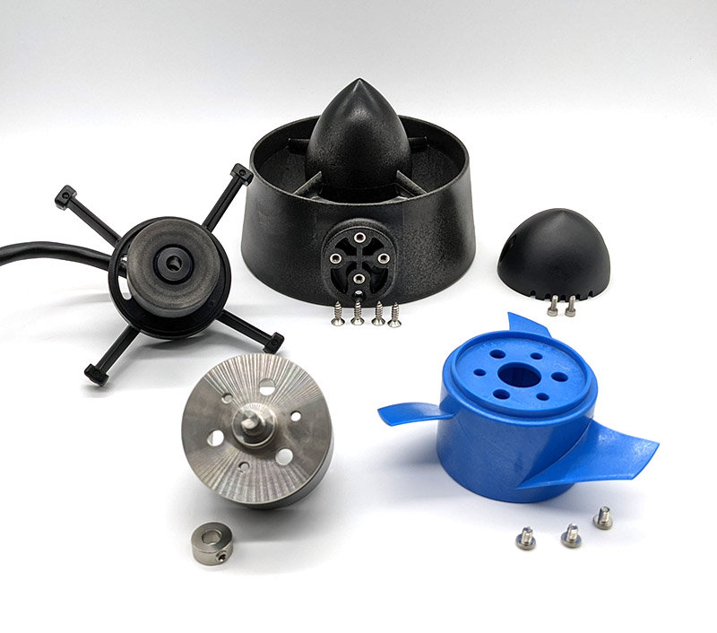
Parts of a Thruster
This diagram shows the main components of a T200 or T500 thruster.
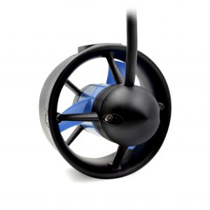
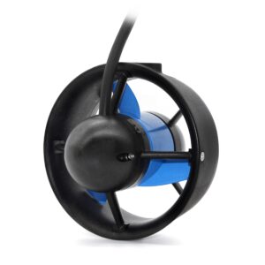
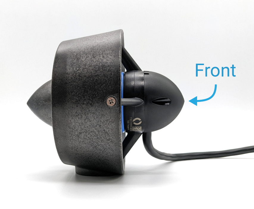
Thruster Direction
The front of the thruster is the side where the cable enters the nose cone.
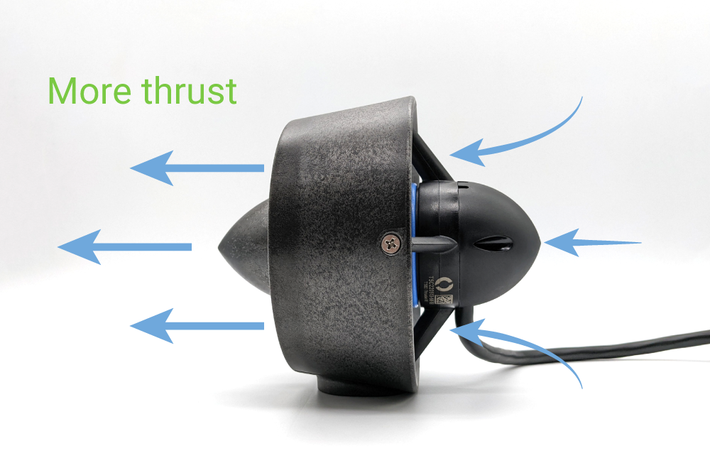
The T200 and T500 are designed to optimize thrust and efficiency when thrusting in the forward direction. The thruster is thrusting in the forward direction when water enters from the front and is expelled through the back of the nozzle.
Forward Thrust: more thrust and greater efficiency
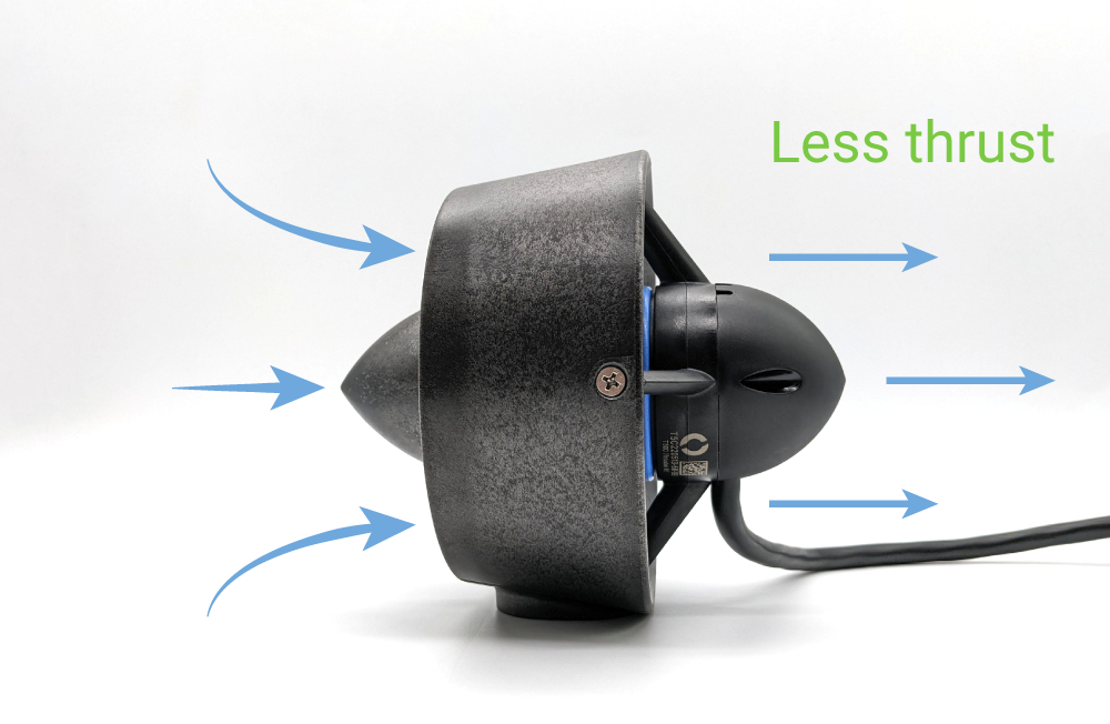
The thruster can also generate thrust in the reverse direction, although at slightly lower force and efficiency.
Reverse Thrust: Less thrust and efficiency
Forward and reverse thrust performance specifications are available in the T200 and T500 performance charts.
Propeller Direction
Every thruster includes both a clockwise rotating propeller and a counterclockwise rotating propeller. The propellers are labeled with “CW” (clockwise) and “CCW” (counterclockwise) for easy identification. Propeller direction can also be determined by viewing the thruster from the front nose cone and looking at the direction of the leading edge of the blades:
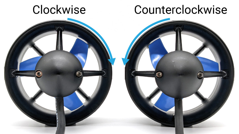
A clockwise propeller will generate forward thrust when spinning in the clockwise direction. Likewise, a counterclockwise propeller will generate forward thrust when spinning counterclockwise.
Both clockwise and counterclockwise propellers can generate thrust in the forward and reverse directions.
What is the other propeller direction for?
When a thruster spins, it creates torque. This torque can cause undesired rotation of the vehicle. To counteract this, opposite (counter-rotating) propellers can be used on pairs of thrusters that are on the same axis to cancel out their torques.
Instructions for switching the installed propeller are available in the Changing a Propeller section of this guide.
Operation
To operate a thruster you need:
- The thruster itself. At the core of a thruster is a brushless DC motor.
- A brushless electronic speed controller (ESC). The ESC manages the power delivered to the thruster, adjusting the speed and direction by controlling the timing of power supplied to the motor’s phases.
- A power source. Typically a battery or external power supply, provides the necessary electrical energy required to operate the ESC and thruster.
- A signal to control the ESC. This signal, usually generated by a remote control or an automated flight control system, directs the ESC on how to modulate the thruster’s output according to desired speed and direction changes.
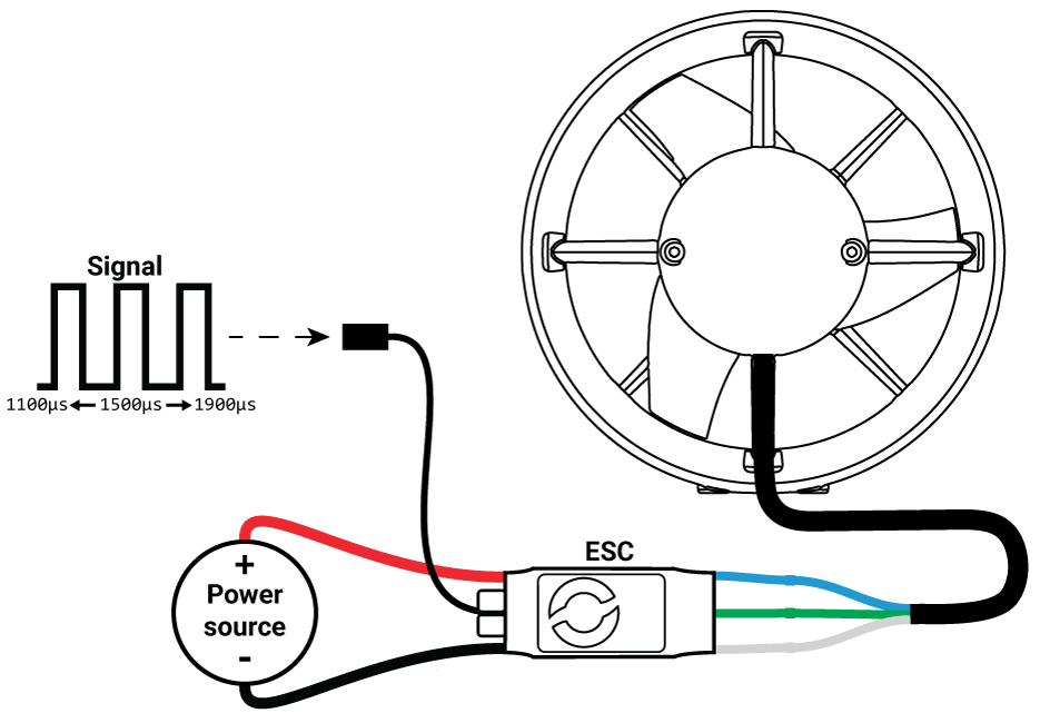
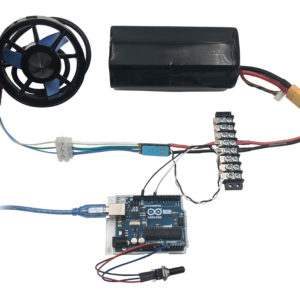
The following diagram shows how everything is connected.
Connecting to an ESC
The thruster cable has three conductors that terminate in tinned wire ends.
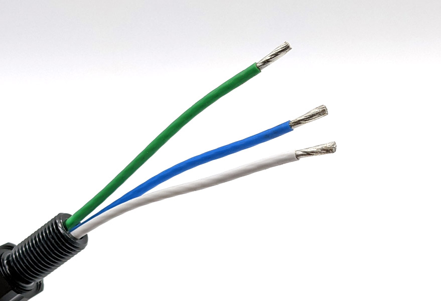
Connect these three thruster wires to the three motor phase wires from the ESC. How you connect the wires is up to your preference. The wires can be soldered together or you can use connectors like bullet connectors or screw terminal blocks. The order does not matter, the thruster will spin with the wires connected in any configuration. If the thruster is spinning in reverse of what is desired, swap the connection of two of the wires.
Connecting to a Power Source
After the thruster is connected to the ESC, connect the red (positive) and black (ground) ESC power wires to a power source. The power source voltage should be within the operating voltage range for the thruster you are powering, this is: 7–20 V for the T200 and 7–24 V for the T500.
When the ESC is connected to power you should hear three beeps in rising pitch indicating the ESC is receiving power.
T500 Voltage Limitation
The T500 Thruster has a maximum operating voltage of 24 V. The T500 can also be powered using a 6S Lithium-ion/Lithium polymer battery (maximum). Continuous full throttle use should be limited to 1 minute or less when the T500 is operated at 24 V or with a fully charged 6S Lithium-ion/Lithium polymer battery to avoid overheating the thruster.
Sending the Signal
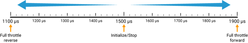
Connect the white ESC signal wire to the signal source output. Connect the black (ground) ESC wire to a ground pin on the signal source device. Send a PWM signal of 1500 microseconds (µs) to initialize the ESC. The ESC must be initialized before it can accept any other throttle signals. When the ESC is initialized you should hear two more beeps. The first beep indicates the ESC detects a throttle signal and the second beep indicates that the correct 1500 µs signal is detected and the ESC is now fully initialized.
After the ESC is initialized, sending a PWM signal from 1100 µs to 1900 µs will control the throttle of the thruster:
- 1500 µs to stop the thruster
- >1525 µs to 1900 µs for forward thrust
- <1475 µs to 1100 µs for reverse thrust
While testing your thrusters, do not operate them for more than 10 seconds outside of water (while dry). The bearings require water for lubrication and may be damaged if the thruster is operated for an extended period of time while dry. You may also notice a clicking noise or that some thrusters are noisier than others. This is normal. Because of the tolerances of the plastic bearings and the metal rotor shafts, the rotor shaft can move slightly in the bearing causing variation in how different thrusters sound. Any noise is significantly reduced or eliminated when operated in water.
If you are having problems with thruster operation please refer to the Troubleshooting section of this guide.
What kind of device can be used as a signal source?
Pretty much anything that can output the correct PWM signal! The PWM signals used by the ESC are the same signals commonly used by RC receivers or to control servos. The following are a few examples of devices that can be used as a PWM signal source:
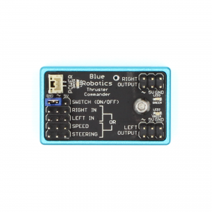
Blue Robotics Thruster Commander
The Thruster Commander is a great way to get started using our thrusters. We recommend it for first-time users and anyone who is not sure about what signal source they should use. It’s also great for controlling thrusters on a stand-up paddle board, kayak, fishing float, etc.
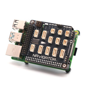
Flight control devices like the Navigator Flight Controller or Pixhawk Autopilots
These devices are used to control unmanned vehicles like ROVs, AUVs, USVs, etc.
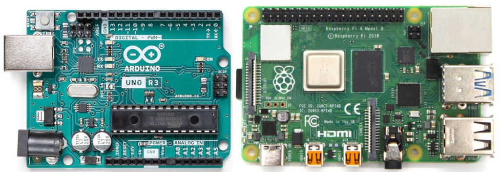
Arduinos, Raspberry Pis, and other types of microcontrollers and SBCs
These can be used for a multitude of projects, from human-operated vehicles to fully autonomous vehicles.
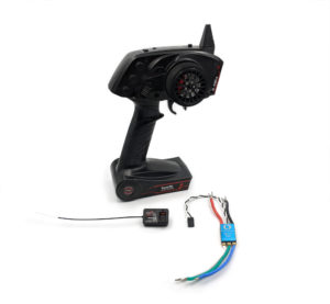
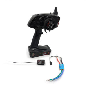
RC transmitters/receivers
These are a good choice for adding simple wireless controls to a vehicle. Just remember, they don’t work underwater!
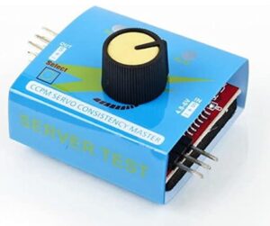
Simple Servo testers
Probably the most simple type of signal source. Servo testers work well for testing thrusters (go figure) or as a super simple, single-input control method.
We have several other guides that explain how to control the ESC and thruster using different devices in greater detail:
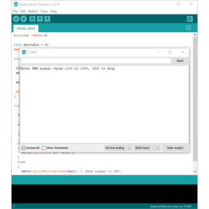
Control the Basic ESC with the Arduino Serial Monitor
Control the Basic ESC with a Potentiometer and Arduino
Control the Basic ESC with an RC Transmitter

Guide to the Thruster Commander
Thruster Mounting
The thrusters have two mounting options:
- Using the four fastener mounting hole pattern
- Using the single fastener center mounting hole
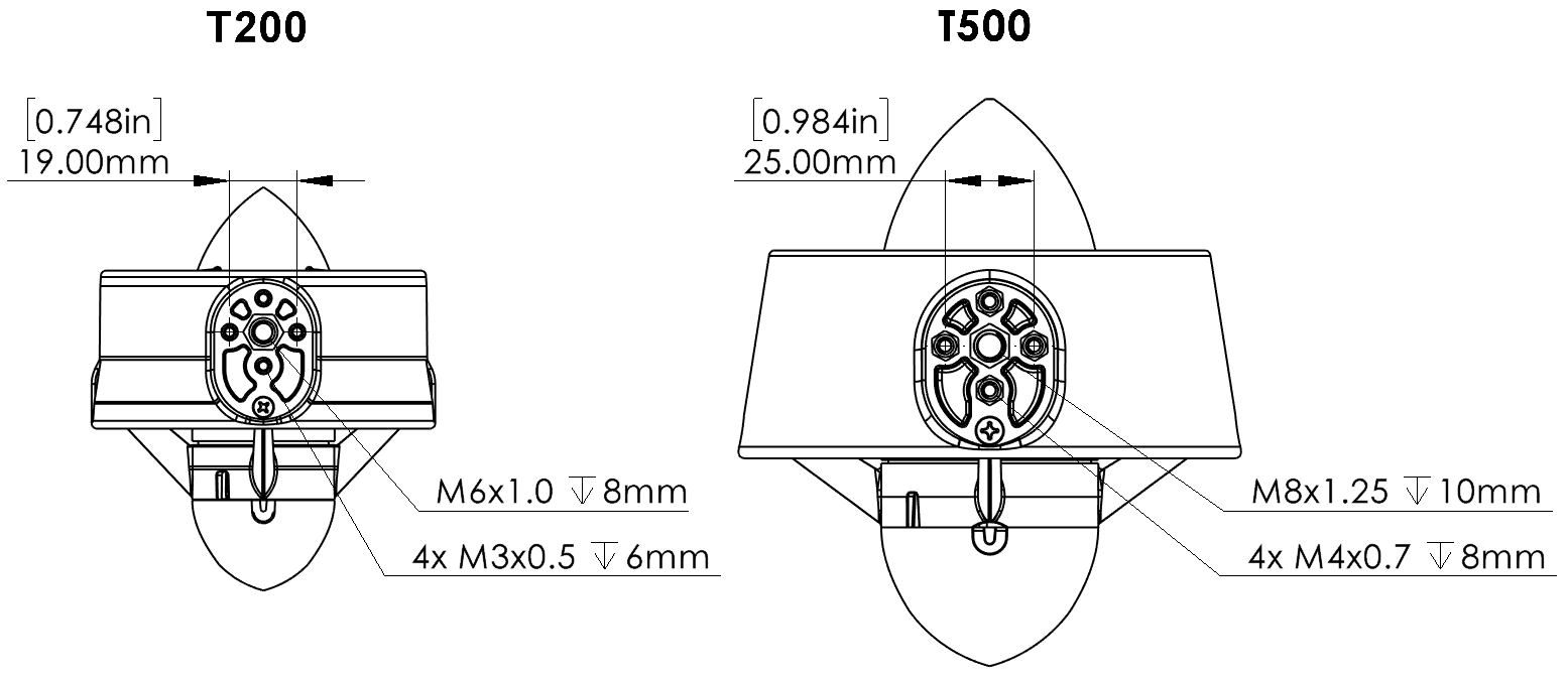
The mounting hole pattern and thread size for each thruster are provided below.
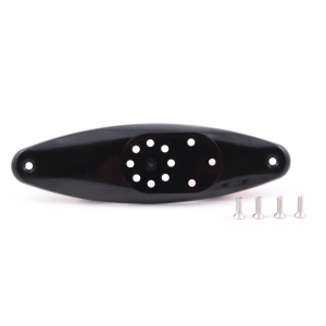
The T200 also has an optional mounting bracket for situations where it is not convenient to use the default mounting location. This bracket is not compatible with the T500 thruster.
Thruster Tools
Refer to the table below for tool and screw sizes. All hardware is 316 stainless steel.
| Screw | T200 | T500 | ||
| Screw Size | Drive | Screw Size | Drive | |
| Nozzle screws | M2.9x12 mm Phillips, flat head, self tapping | #2 Phillips | M3.9x13 mm Phillips, flat head, self tapping | #2 Phillips |
| Nose cone screws | M3x8 mm socket head cap | 2.5 mm hex | M3x8 mm socket head cap | 2.5 mm hex |
| Propeller screws | M3x5 mm button head cap | 2.0 mm hex | M4x6 mm button head cap | 2.5 mm hex |
| Shaft collar set screw | M4x4 mm set screw | 2.0 mm hex | M5x6 mm set screw | 2.5 mm hex |
Changing a Propeller
Every thruster includes both a clockwise rotating propeller and a counterclockwise rotating propeller. Changing the installed propeller is quick and easy. Refer to the Thruster Tools table for exact tool sizes.
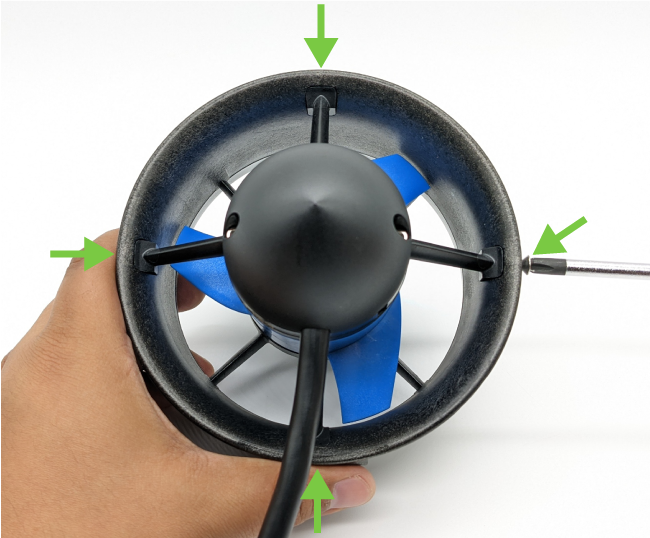
1. Use a Phillips screwdriver to remove the four nozzle screws from the nozzle then pull the nozzle away from the rest of the thruster.
2. Remove the propeller screws using a hex driver and pull the propeller off of the rotor.
3. A different propeller can now be installed onto the rotor.
4. Follow the directions in reverse to reassemble the thruster.
Thruster Disassembly and Reassembly
You may have to take apart your thruster occasionally for cleaning and maintenance. Follow the instructions below to disassemble your thruster. Refer to the Thruster Tools table above for exact tool sizes.
1. Use a Phillips screwdriver to remove the four nozzle screws from the nozzle then pull the nozzle away from the rest of the thruster.
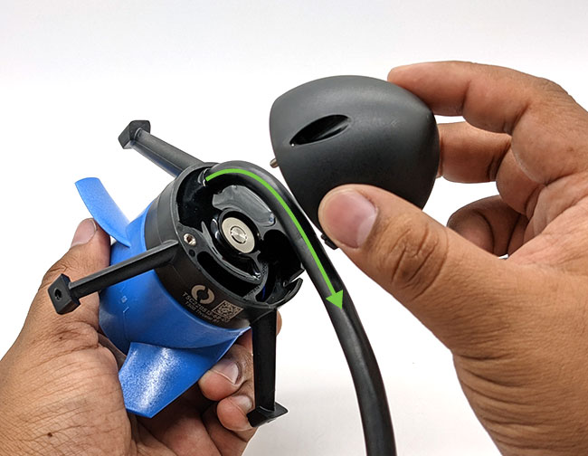
2. Use a hex driver to remove the two nose cone screws.
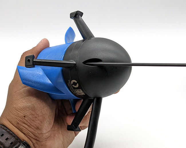
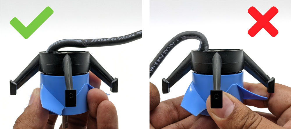
3. Remove the nose cone. Take notice of how the thruster cable bends and exits the nose cone on the opposite side. This is important when reassembling the thruster.
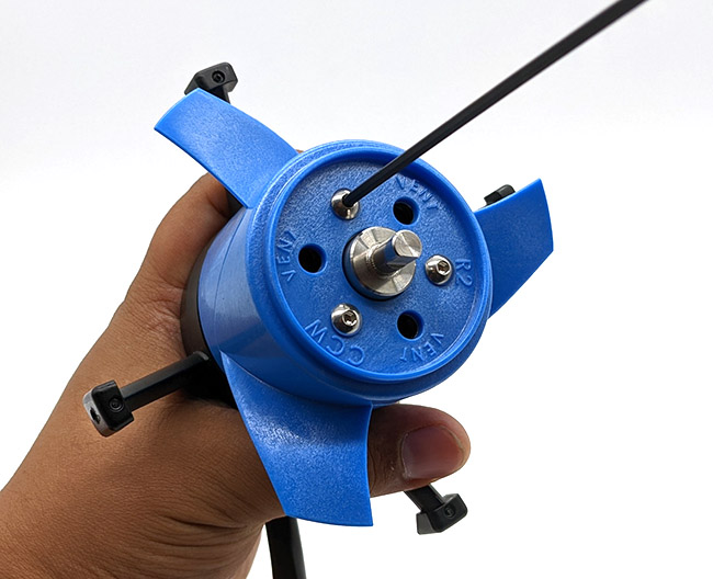
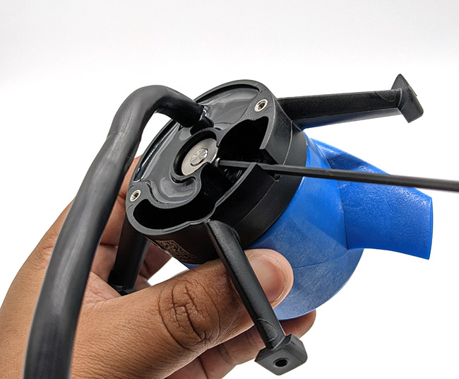
4. Rotate the propeller by hand until the shaft collar set screw lines up with the notch in the stator base. Use a hex driver to loosen the set screw.
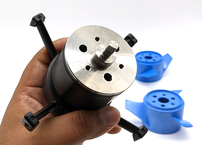
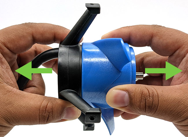
5. Do not pry up on the shaft collar to remove it. Instead, pull the propeller away from the thruster core to separate it from the stator.
6. Use a hex driver to remove the propeller screws.
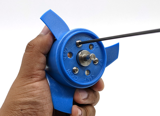
7. With the propeller screws removed, you can separate the propeller from the rotor. Your thruster is now completely disassembled.
Reassembly
1. Install the propeller onto the rotor using the propeller screws and a hex driver.
2. Ensure the shaft collar is in the stator base then install the propeller and rotor onto the thruster core.
3. Use a hex driver to tighten the shaft collar set screw onto the flat side of the rotor shaft.
4. Install the nose cone onto the core making sure the cable exits the nose cone on the opposite side. Do not bend the cable in the other direction.
5. Install the nozzle using the nozzle screws and a Phillips screwdriver.
Care and Maintenance
After Use in Saltwater
- Rinse thoroughly with freshwater to flush out salt and mineral deposits. The best way to do this is to submerge the thruster in freshwater and run it for a few seconds.
After Using The Thrusters In Sandy Or Sediment Heavy Environments
Operating in environments with a lot of sand, silt, sediment, ferrous particles, or other abrasives will scratch the protective coating on the rotors. Heavily damaged coating will eventually cause the rotor to corrode and seize the thruster.
- Avoid getting sand into the thrusters if you can prevent it.
- If you must operate in these types of conditions, disassemble the thruster and clean out the sand or other abrasives from the rotor.
- Replace the rotor if the coating is damaged and showing signs of corrosion. Replacement T200 and T500 rotors are available on our website.
Every Five to Ten Uses
- Inspect the inside of the rotors and remove any buildup.
- Inspect the cable jacket for damage.
Troubleshooting
ESC Beeps
When a thruster is connected to an ESC, the ESC can use it as a “speaker” to play a series of beeps. These beeps provide information about the status of the ESC and are useful for troubleshooting. Both the Basic ESC and Basic ESC 500 have slightly different beeping patterns.
Basic ESC
1. At power on the ESC will beep three times in rising pitch. If you do not hear these beeps:
- The ESC may not be receiving power. Check your power supply and all power connections.
- The thruster may not be connected correctly to the ESC. Check that there is a good connection between the three ESC motor wires and the thruster wires.
- The ESC may be defective.
2. If any throttle signal is detected the ESC will then beep one time. If you do not hear this beep:
- It means the ESC is not receiving any sort of throttle signal. Check the signal source to see if it is powered on and sending the correct signal.
- Check the connection between the signal source and the white ESC signal wire.
3. If the initialize/stop signal (1500 µs) is detected the ESC will beep one final time indicating that it is fully initialized. If you do not hear this beep:
- It means the ESC is not receiving the correct 1500 µs signal. Check if your signal source is sending the correct 1500 µs signal.
Basic ESC 500
1. At power on the ESC will beep once. If you do not hear this beep:
- The ESC may not be receiving power. Check your power supply and all power connections.
- The thruster may not be connected correctly to the ESC. Check that there is a good connection between the three ESC motor wires and the thruster wires.
- The ESC may be defective.
2. If the initialize/stop signal (1500 µs) is detected the ESC will beep three times in rising pitch indicating that it is fully initialized. If you do not hear these beeps:
- It means the ESC is not receiving the correct 1500 µs signal. Check if your signal source is powered on and sending the correct 1500 µs signal.
- Check the connection between the signal source and the white ESC signal wire.
The thruster does not spin or move at all
- This is usually an issue with the improper operation of the ESC. Refer to the ESC Beeps section above to troubleshoot the ESC.
The propeller tries to move but does not spin correctly
- All three thruster wires may not be connected to the ESC motor wires correctly. Check that there is a good connection between the three ESC motor wires and the thruster wires.
- There may be a broken thruster wire or a short between thruster wires. Check the resistance of each thruster wire pair (blue wire/green wire, blue wire/white wire, green wire/white wire) using a multimeter. Each thruster wire pair should have the same resistance within 0.1-0.2ohms or so. If there is no continuity between a pair, or one pair has significantly higher resistance, the thruster is defective.
- Try to rotate the propeller by hand, it should spin freely. If it is difficult to rotate, disassemble the thruster and check for damage or blockage.
The propeller is jammed and cannot be turned by hand
- This can be caused by something jamming the propeller or by major internal damage caused by overheating, short circuits, heavily worn bearings, etc. Completely disassemble the thruster and inspect for damage or blockage.
Swap-Components Troubleshooting
A great way to troubleshoot a problem is to swap components with other known-working components and observe whether the problem stays in place or moves with the component. To troubleshoot a thruster using this method you will need an different thruster and ESC set that you have confirmed is working normally.
1. Swap the problematic thruster with a thruster that you know works well. That is, connect the problematic thruster to the ESC that was connected to the working thruster and connect the working thruster to the ESC that was connected to the problematic thruster. If the problem follows the thruster, you know that the thruster is defective. If the problem stays with the ESC, move on to the next step.
2. Swap the signal sources of the ESCs. If the problem follows the problematic ESC, you know the ESC is defective. If the problem stays with the signal source, then there is a problem with the signal source.
Feedback
We’re always trying to make our documentation, instructions, software, and user experience better. If you’d like to leave feedback about how we can make this guide better, let us know here.