
Navigator Retrofit Guide
Introduction
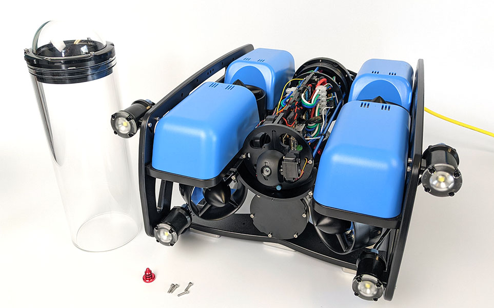
The Navigator is our new flight controller board for ROVs or other vehicles. It replaces the Pixhawk 1 autopilot used in older versions of the BlueROV2. This guide will show you how to uninstall the old autopilot hardware and install a new Navigator Flight Controller in your BlueROV2.
Parts and Tools
You Will Need
You will also need:
- 1 x 2.5 mm hex driver (from BlueROV2 kit)
- 1 x 1.5 mm hex key (from BlueROV2 kit)
- 1 x #1 Phillips head screwdriver (not included)
- Tape and pen
Uninstalling the Pixhawk and Raspberry Pi 3
Out with the old and in with the new! The old hardware from the BlueROV2 needs to be removed before you can install your shiny new Navigator flight controller. To do this you will need:
- #1 Phillips head screwdriver
- 2.5 mm hex driver
- Tape and pen to label the wires
Opening the Electronics Enclosure
1. Use the 2.5 mm hex driver to remove the four M3x16 screws that secure the Electronics Enclosure mounting clips to the enclosure cradles and set them to the side.
2. Remove the Electronics Enclosure vent plug from the vent bulkhead and set it to the side.
3. Remove the Electronics Enclosure tube from the Electronics Enclosure assembly.
Disconnecting the Components
If you are not very familiar with the components inside the electronics enclosure, we recommend labeling the cables with tape and a pen as you remove them. This will make connecting them to the Navigator easier. The following instructions and locations of the wires are assuming your BlueROV2 is in a normal configuration. If your wires do not match what is shown here, follow the wires back to the components and label them appropriately.
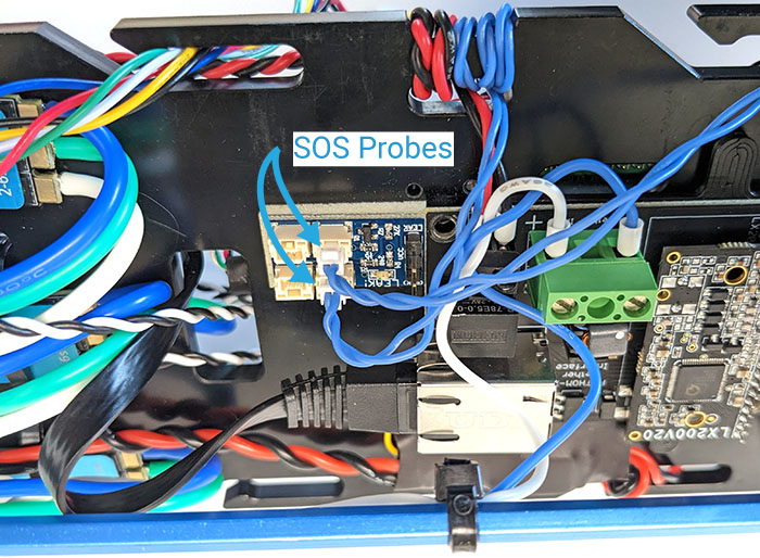
1. Disconnect the SOS leak sensor cable from AUX channel 6.
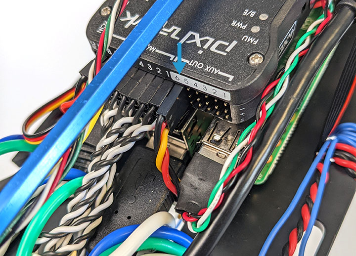
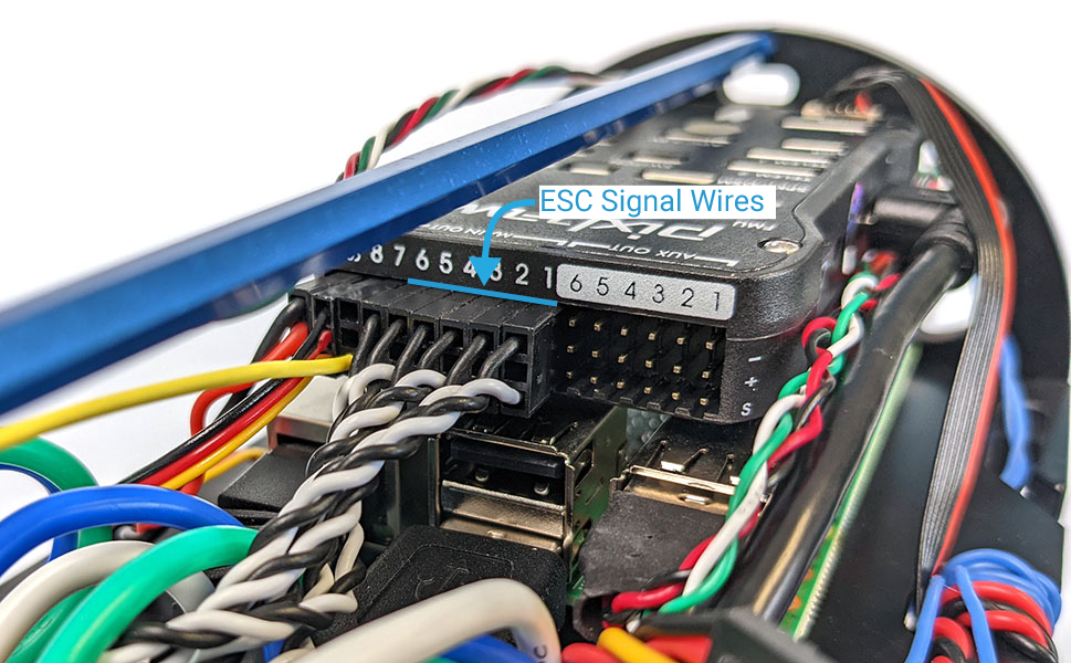
2. The next set of wires connected to output channels 1 through 6, or 1 through 8 for a BlueROV2 Heavy, are the ESC signal wires. Each ESC is assigned a specific output channel so it is particularly important to keep track of the channel each ESC is connected to. Label each ESC signal wire according to the channel it is connected to. For example, the ESC on channel 1 is ESC 1, the ESC on channel 2 is ESC 2, and so on.
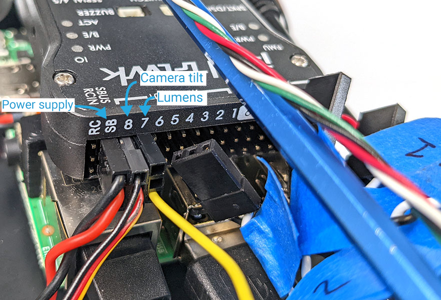
3. Disconnect the yellow Lumen signal wire. This will be connected to output channel 7 in a standard BlueROV2 or AUX 1 in a BlueROV2 Heavy.
4. Disconnect the camera tilt servo. This will be connected to output channel 8 in a standard BlueROV2 or AUX 2 in a BlueROV2 Heavy.
5. Disconnect the 5 V power supply from the “SBUS” channel.
6. Disconnect any other accessories that are connected to the Pixhawk servo rail or Raspberry Pi and label them.
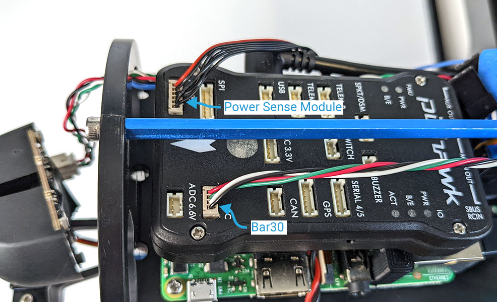
7. Disconnect the Bar30 sensor from the “I2C” port. It can sometimes be difficult to disconnect the connector from the port, try using a small flat head screwdriver to gently pry up the connector to remove it. Do not pull directly from the wires.
8. Disconnect the Power Sense Module cable from the “POWER” port.
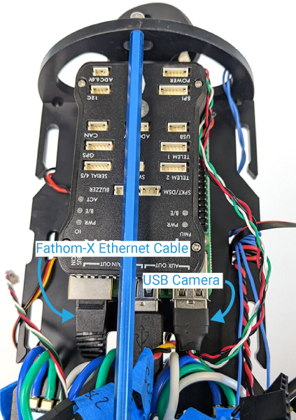
9. Disconnect the USB camera cable from the Raspberry Pi USB port.
10. Disconnect the Fathom-X Ethernet cable from the Raspberry Pi Ethernet port.
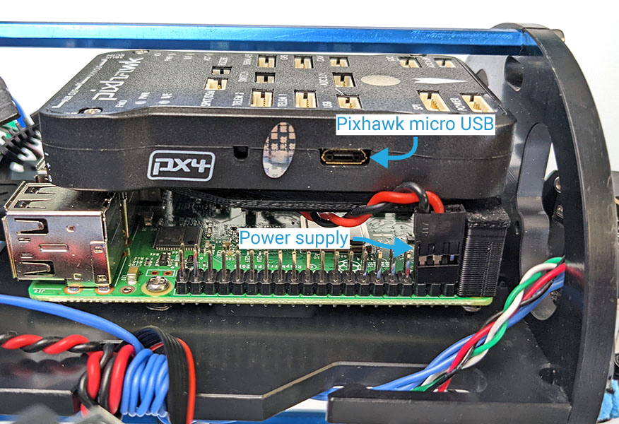
11. Disconnect the other 5 V power supply output from the Raspberry Pi GPIO.
12. Disconnect the USB cable from the micro USB port on the side of the Pixhawk. This cable will not be used but it makes removing the Pixhawk and Raspberry Pi easier.
Unmounting
1. Use a #1 Phillips screwdriver to remove the two mounting screws that secure the Raspberry Pi to the electronics tray.
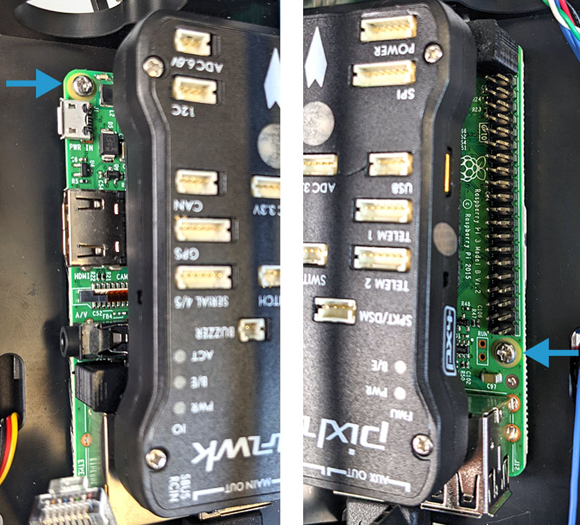
2. With all of the electronics components disconnected and the mounting screws removed, the Raspberry Pi, plastic standoff, and Pixhawk can be removed from the electronics tray.
Installing the Navigator Stack
Assembly
The Navigator kit includes all the required components and hardware to connect it to the Raspberry Pi 4. To assemble the Navigator stack, you will need:
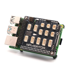
- Navigator PCB
- Navigator heatsink
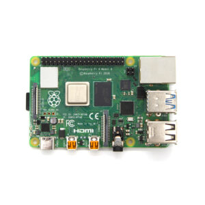
- Raspberry Pi 4 Model B
- SD card with BlueOS
- Thermal pads
- Raspberry Pi mounting standoff
- 4 x M2.5×8 button head cap screw
You will also need the following tools:
- 1.5 mm hex driver
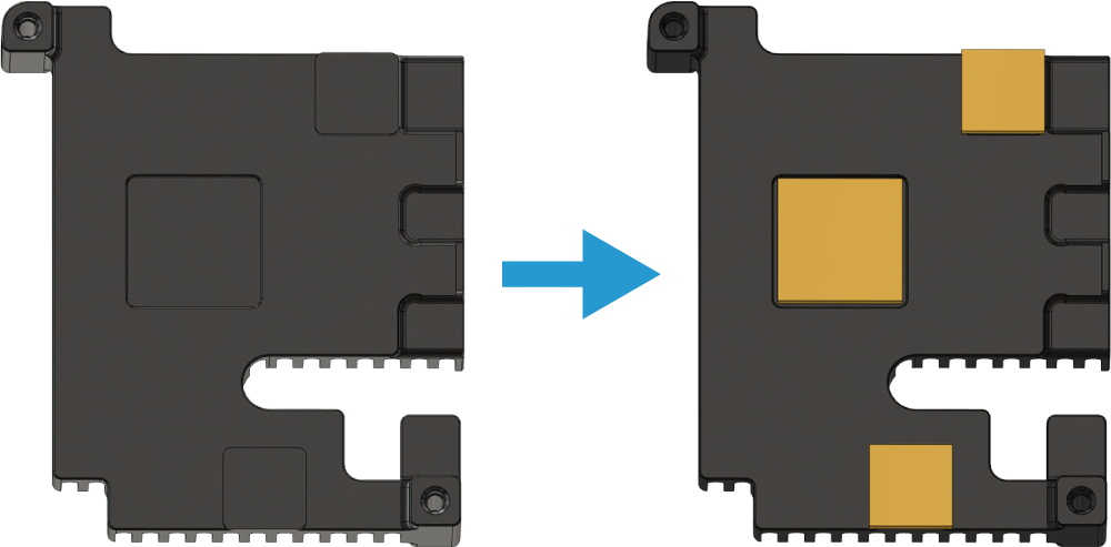
1. Remove the protective covering from the square thermal pads and apply them to the underside of the Navigator heatsink. The heatsink has squares showing where the thermal pads should be placed.
2. Place the Navigator heatsink on top of the Raspberry Pi 4. The thermal pads should sit between the Navigator heatsink and the Raspberry Pi.
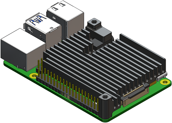
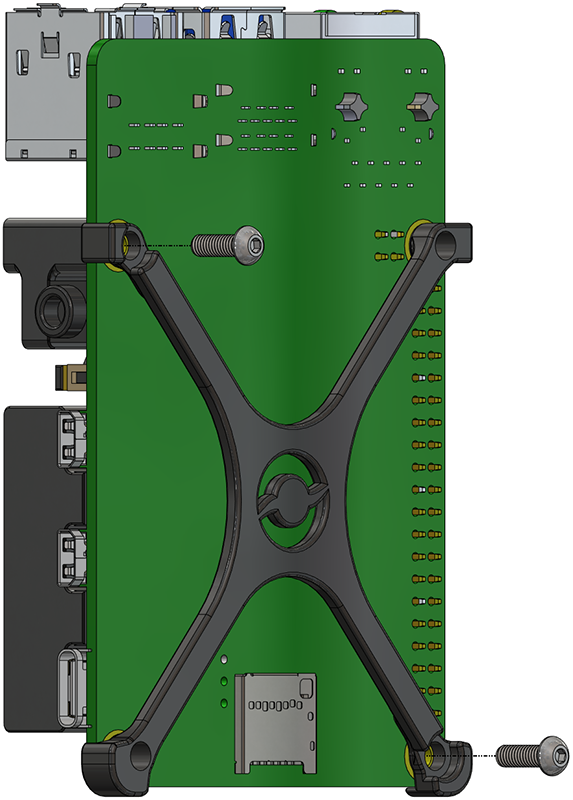
3. Place the Raspberry Pi mounting standoff on the underside of the Raspberry Pi. Use two M2.5×8 button head screws and the 1.5 hex driver to secure the standoff and Navigator heatsink to the Raspberry Pi. The screws should sit in the recessed standoff mounting holes and screw into the heatsink.
4. Place the Navigator PCB on top of the Raspberry Pi and heatsink and plug it fully onto the Raspberry Pi GPIO pins. Secure the Navigator PCB to the heatsink using the remaining M2.5×8 button head screws.
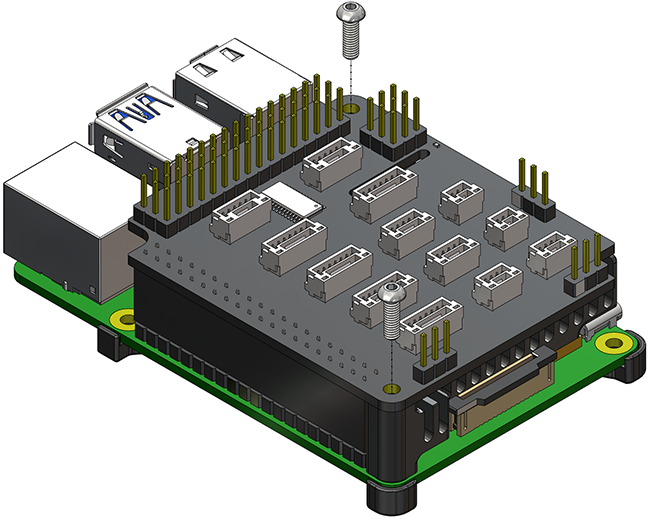
5. Insert the included BlueOS microSD card with into the Raspberry Pi microSD card connector.
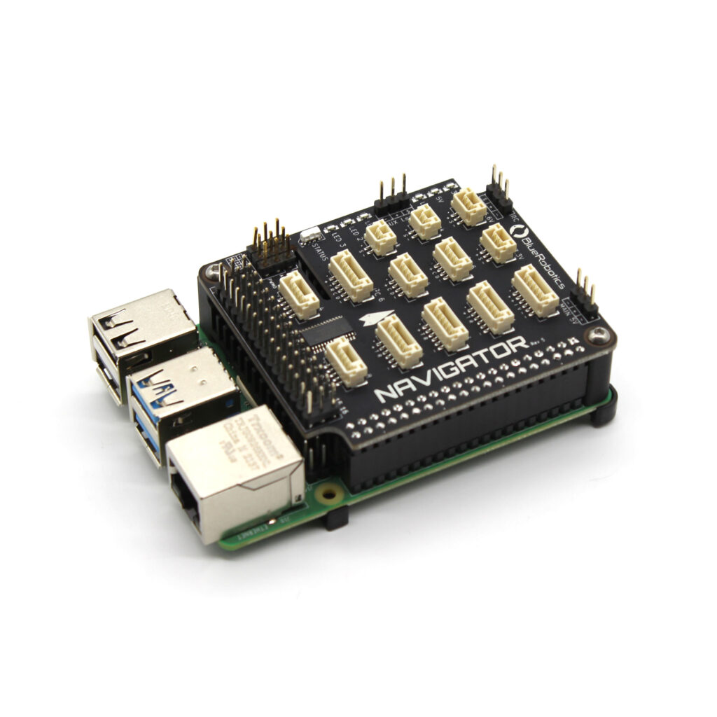
The Navigator stack is now ready to install in your BlueROV2.
Mounting the Navigator Stack
To install the Navigator stack onto the electronics tray, you will need:
- #1 Phillips head screwdriver
- 2 x #3-28×3/8 mounting screws (from Navigator kit)
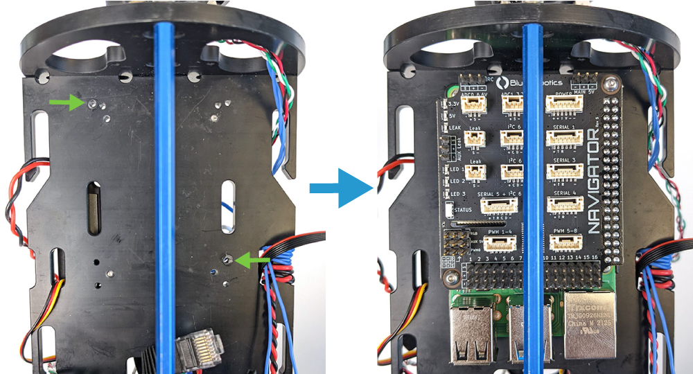
1. Place the assembled Navigator stack on the electronics tray where the Pixhawk and Raspberry Pi were installed. Line up the Raspberry Pi mounting holes with the electronics tray mounting holes shown below. The arrow on the Navigator should be pointing to the front of the vehicle where the camera is.
2. Secure the Navigator stack to the electronics tray using two #3-28×3/8 mounting screws and the Phillips head screwdriver.
Connecting Components
For the following steps you will need:
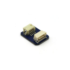
- 1 x JST GH to DF13 adapter
- 1 x 6 wire JST GH to JST GH accessory cable (from Navigator kit)
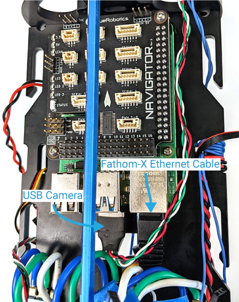
1. Connect the Fathom-X Ethernet cable to the Raspberry Pi 4 Ethernet port.
2. Connect the Camera USB cable to one of the Raspberry Pi 4 USB ports.
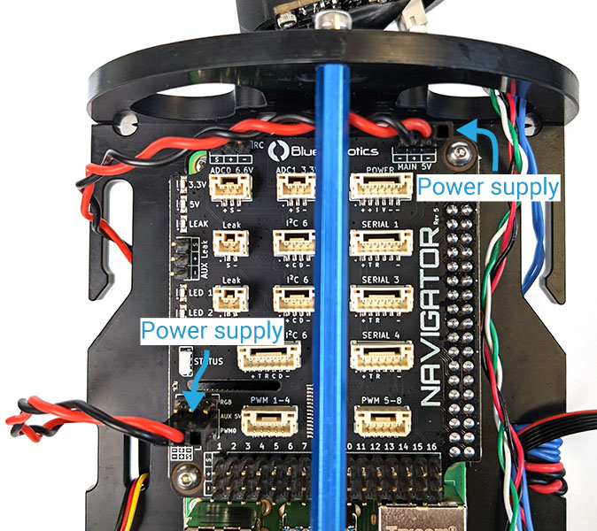
3. Connect one of the 5 V power supply outputs to the “MAIN 5V” port. Connect the other 5 V power supply output to the “AUX 5V” port. Both power input ports are reversible so the power supply connectors can be connected in either orientation.
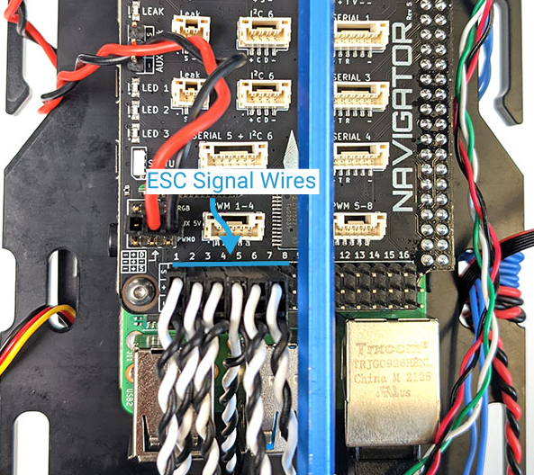
4. Connect all of the ESC signal wires to the Navigator servo rail. Starting with ESC 1, connect each ESC signal wire to the corresponding output channel of the same number (ESC 1 to channel 1, ESC 2 to channel 2, etc.). The ESCs should occupy channels 1 through 6 on a standard BlueROV2 or 1 through 8 on a BlueROV2 Heavy. It may be necessary to reroute some of the ESC signal wires through the electronics tray if they do not easily reach the Navigator servo rail.
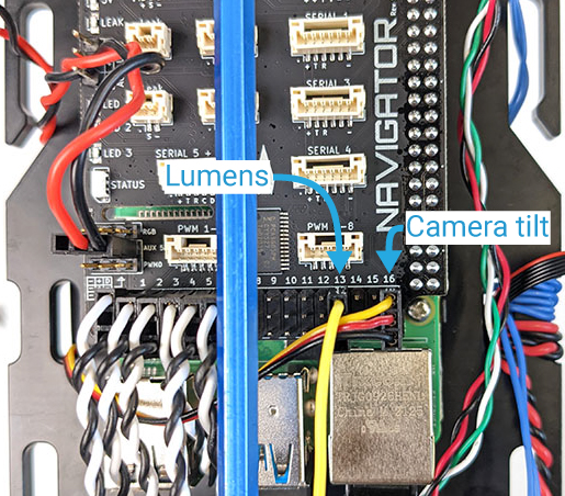
5. Connect the yellow Lumen signal wire to output channel 13.
6. Connect the camera tilt servo to output channel 16.
7. If you have a Newton Gripper, connect it to output channel 9, 10, or 11 and follow the integration instructions. Connect any other accessories such as the Ping2 sonar or Ping360 according to their instructions.
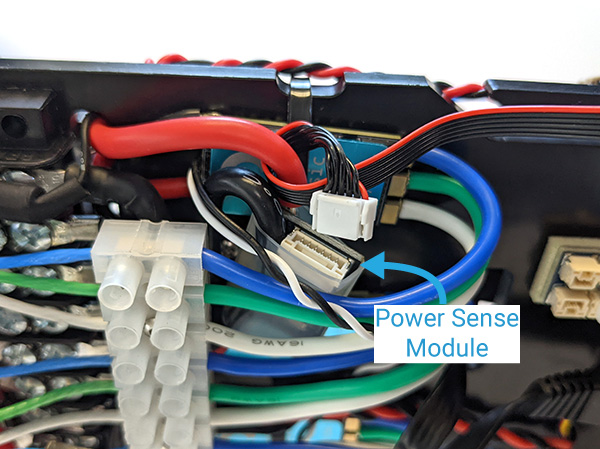
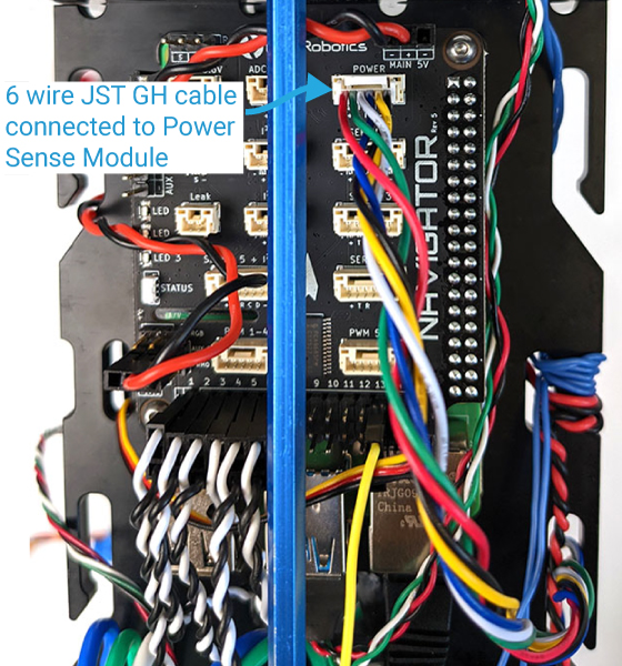
8. Disconnect the existing 6 wire cable from the Power Sense Module, this cable will no longer be used. Replace this cable with a 6 wire JST GH to JST GH accessory cable from the Navigator kit. Plug it into the Power Sense Module and plug the other end into the “POWER” port on the Navigator.
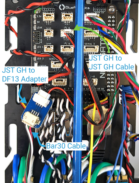
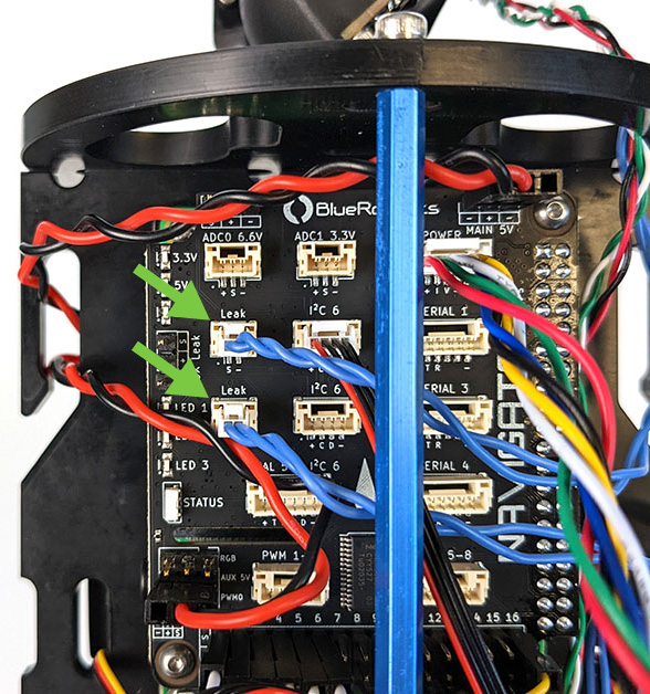
9. Connect the Bar30 cable to the DF13 connector side of the JST GH to DF13 adapter. Connect the included JST GH to JST GH extension cable to the adapter and plug it into one of the “I2C 6″ ports on the Navigator.
10. Disconnect the leak detection probes from the SOS Leak Detector and connect them directly to the “Leak” ports on the Navigator. The Navigator has a built-in leak detection circuit so the separate SOS Leak Detector module is no longer required.
Default Output Channel Configuration
The default configuration of the servo rail outputs for a BlueROV2 and BlueROV2 Heavy Configuration are provided below for reference.
| Output Channel | Servo Number | Connected Device/Function | SERVO#_FUNCTION Parameter |
|---|---|---|---|
| BlueROV2 | |||
| 1 | SERVO1 | Thruster 1 | Motor1 |
| 2 | SERVO2 | Thruster 2 | Motor2 |
| 3 | SERVO3 | Thruster 3 | Motor3 |
| 4 | SERVO4 | Thruster 4 | Motor4 |
| 5 | SERVO5 | Thruster 5 | Motor5 |
| 6 | SERVO6 | Thruster 6 | Motor6 |
| 7 | SERVO7 | Not used | Disabled |
| 8 | SERVO8 | Not used | Disabled |
| 9 | SERVO9 | servo_1 button function (Newton Gripper) | Disabled |
| 10 | SERVO10 | servo_2 button function (Newton Gripper) | Disabled |
| 11 | SERVO11 | servo_3 button function (Newton Gripper) | Disabled |
| 12 | SERVO12 | Not used | Disabled |
| 13 | SERVO13 | Lumen lights | RCIN9 |
| 14 | SERVO14 | Lights 2 (optional) | RCIN10 |
| 15 | SERVO15 | Not used | Disabled |
| 16 | SERVO16 | Camera tilt servo | MountTilt |
| BlueROV2 Heavy | |||
| 1 | SERVO1 | Thruster 1 | Motor1 |
| 2 | SERVO2 | Thruster 2 | Motor2 |
| 3 | SERVO3 | Thruster 3 | Motor3 |
| 4 | SERVO4 | Thruster 4 | Motor4 |
| 5 | SERVO5 | Thruster 5 | Motor5 |
| 6 | SERVO6 | Thruster 6 | Motor6 |
| 7 | SERVO7 | Thruster 7 | Motor7 |
| 8 | SERVO8 | Thruster 8 | Motor8 |
| 9 | SERVO9 | servo_1 button function (Newton Gripper) | Disabled |
| 10 | SERVO10 | servo_2 button function (Newton Gripper) | Disabled |
| 11 | SERVO11 | servo_3 button function (Newton Gripper) | Disabled |
| 12 | SERVO12 | Not used | Disabled |
| 13 | SERVO13 | Lumen lights | RCIN9 |
| 14 | SERVO14 | Lights 2 (optional) | RCIN10 |
| 15 | SERVO15 | Not used | Disabled |
| 16 | SERVO16 | Camera tilt servo | MountTilt |
Finishing the Installation
To finish the installation you will need:
- 2.5 mm Hex driver
1. Reinstall the Electronics Enclosure tube onto the Electronics Enclosure assembly.
2. Mount the Electronics Enclosure back onto the cradles using the hex driver and the M3x16 screws you removed previously.
3. Reinstall the vent plug into the vent bulkhead.
4. Power on the BlueROV2 by plugging in a battery and proceed with the software setup.
Software Setup
Setting up your BlueROV2 with a new Navigator follows the same procedure as setting up a newly built BlueROV2. To do that, follow the instructions in our BlueROV2 Software Setup guide.
BlueROV2 Software Setup
After the software setup is complete, perform the software setup for any additional accessories connected to the BlueROV2.
Feedback
We are always trying to make our documentation, instructions, software, and user experience better. If you would like to leave feedback about how we can make this guide better, let us know here.