
Newton Subsea Gripper Installation on a BlueROV2
Introduction
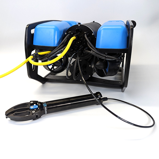
The Newton Gripper provides the BlueROV2 and other subsea vehicles with the ability to interact with the subsea environment to retrieve objects, attach recovery lines, or free a snagged tether!
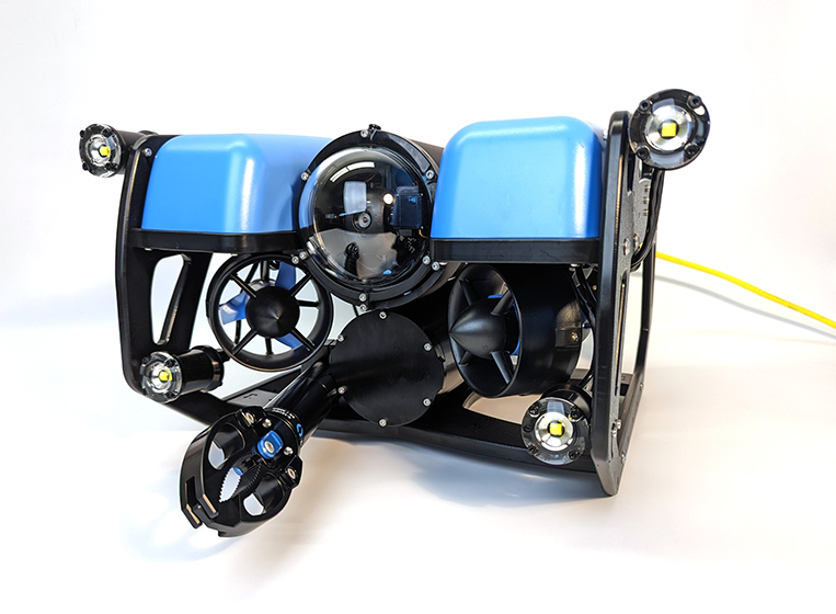
This guide will show you how to install and operate the Newton Gripper on the BlueROV2.
Parts and Tools
You Will Need
To complete the installation, you will also need the following tools (not included):
- M10 Bulkhead Wrench
- 2.5 mm hex driver
- 3 mm hex driver
- #2 Phillips screwdriver
- Silicone grease (Molykote 111)
- Medium-strength thread locker such as Loctite 242 or 243
Preparing the BlueROV2
You will have to open up the BlueROV2 Electronics Enclosure and remove one of the penetrators to install the Newton Gripper. To do this you will need:
- 2.5 mm hex driver
- M10 Bulkhead Wrench
If you are not sure how to perform any of the steps in this section, more detailed instructions for each operation are available in the ‘Servicing the BlueROV2’ section of the BlueROV2 Operation guide.
1. Make sure your BlueROV2 is completely powered off by disconnecting the battery.
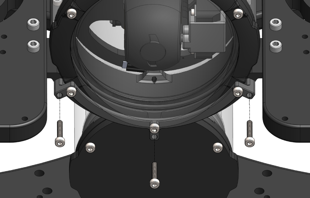
2. Use the 2.5 mm hex to remove the M3x16 mounting screws that secure the enclosure mounting clips to the cradles, remove the PRV or vent plug, and remove the Electronics Enclosure tube from the Electronics Enclosure assembly.
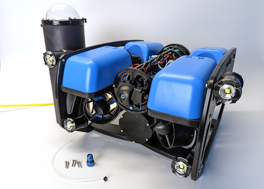
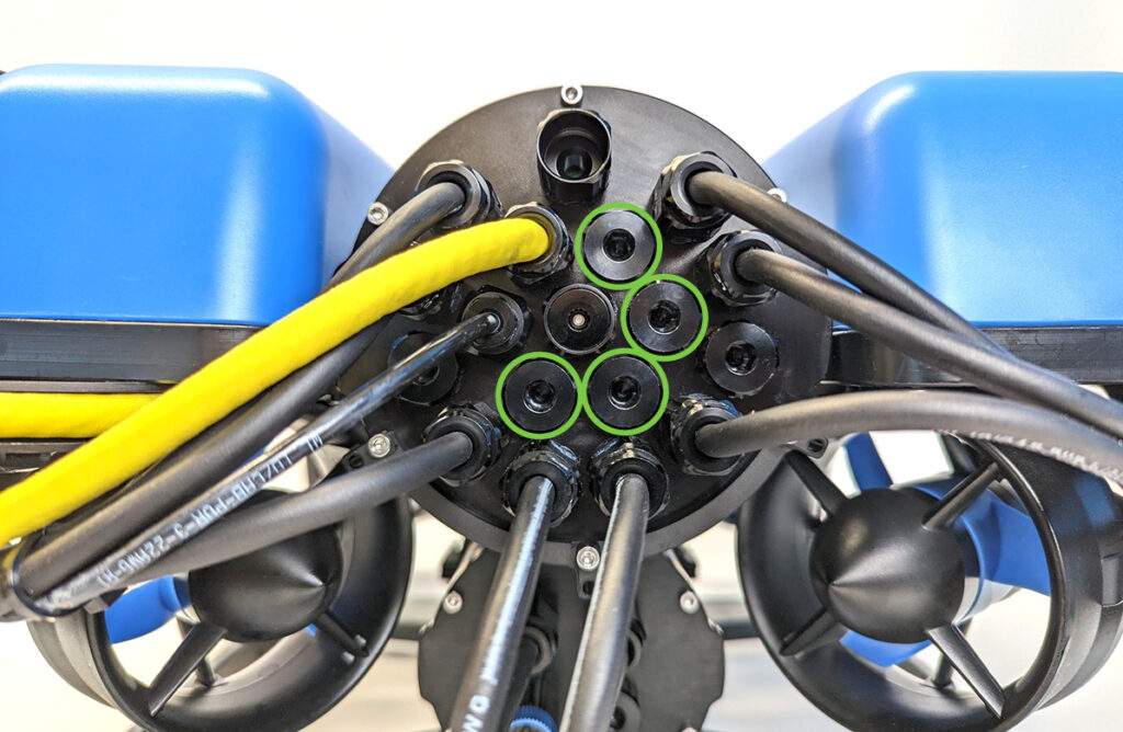
3. Choose one of the blank penetrators in the middle of the end cap and use the M10 Bulkhead Wrench to remove it.
Installing the Penetrator
To install the Gripper’s penetrator into the end cap, you will need the following parts and tools:
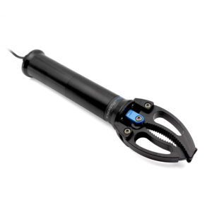
- 1 x Newton Gripper
- 1 x Penetrator nut (included with the Newton Gripper)
- 1 x Penetrator O-ring (included with the Newton Gripper)
- Silicone grease (Molykote 111)
- M10 Bulkhead Wrench
1. Wipe the exterior surface of the end cap around the penetrator hole you previously removed the blank penetrator from. Ensure the area around the hole where the O-ring will sit is free of dust or debris.
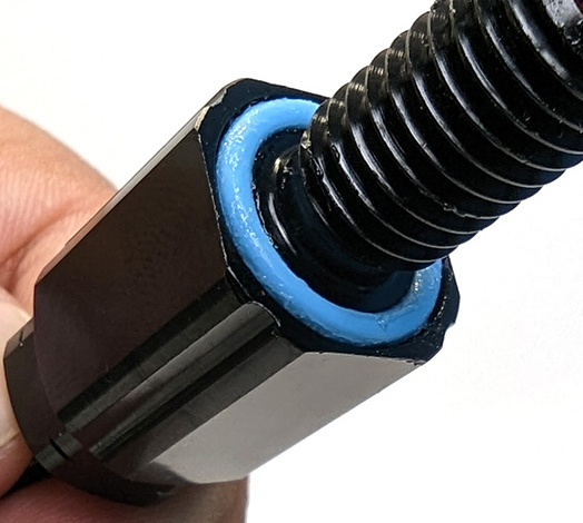
2. Inspect the penetrator O-ring to make sure it is not dirty or damaged.
3. Lubricate the O-ring with a thin layer of silicone grease and install it in the groove on the underside of the penetrator.
4. Install the penetrator in the hole and fasten the penetrator nut on the other side. Tighten the nut and bulkhead by hand until finger-tight. Use the Bulkhead Wrench to fully tighten the penetrator. The penetrator should no longer rotate in the hole and you should not be able to loosen it using your fingers when installed properly.
Wire Connections
With ArduSub 4.5.5 and newer, the Newton Subsea Gripper can be connected to any PWM output channel as long as it is correctly configured in software.
1. Plug the yellow signal wire to the correct output channel on the autopilot:
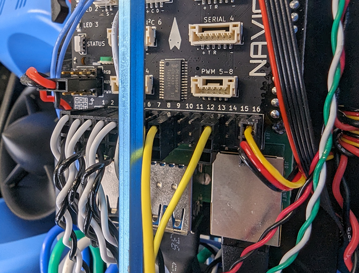
Navigator
For ROVs equipped with a Navigator Flight Controller, plug the signal wire into any available output channel, with the yellow wire in the top position (in line with the other white wires). Note down which channel you connected it to.
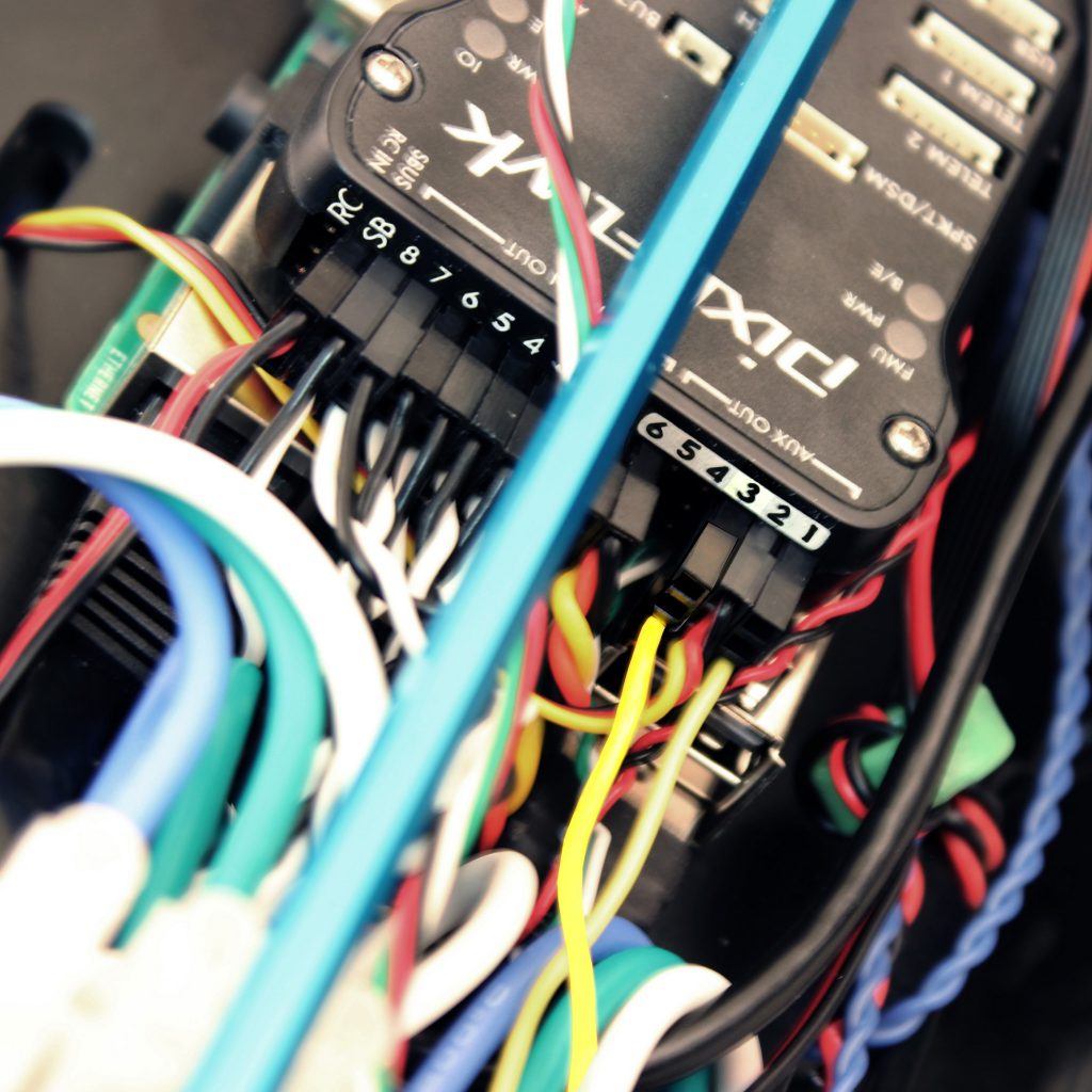
Pixhawk
For older ROVs equipped with a Pixhawk Autopilot, plug the signal wire into any available channel with the yellow wire oriented toward the bottom of the Pixhawk (in line with the other white wires). Note down which channel you connected it to.
Pixhawk flight controller boards have separate MAIN and AUX output pins, so servo channel numbering continues from the MAIN outputs to the AUX outputs. For example, MAIN outputs 1 through 8 correspond to SERVO outputs 1 through 8, while AUX outputs 1 through 6 correspond to SERVO outputs 9 through 14. When wiring the gripper, make sure the physical connection matches the actuator number being configured.
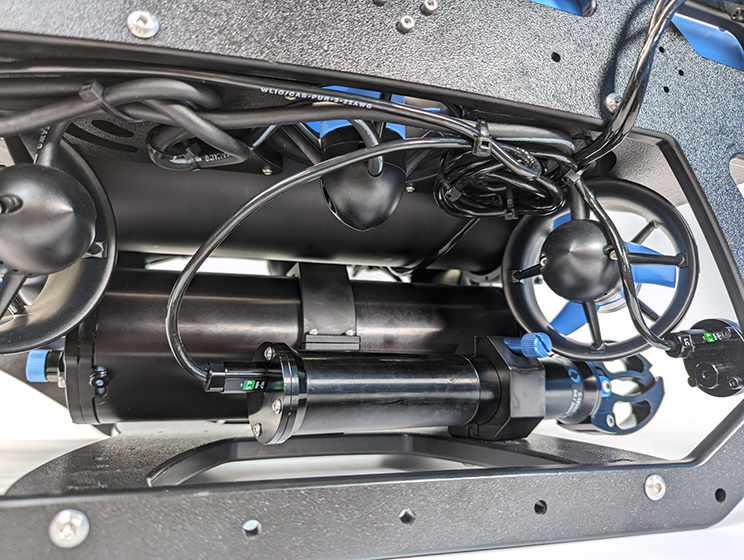
2. Use the #2 Phillips head screwdriver to connect the spade connectors at the end of the red and black power wires to the corresponding screw terminals on the power terminal blocks. Connect the black power wire to the terminal block that contains the other black wires and connect the red power wire to the terminal block that contains the other red wires.
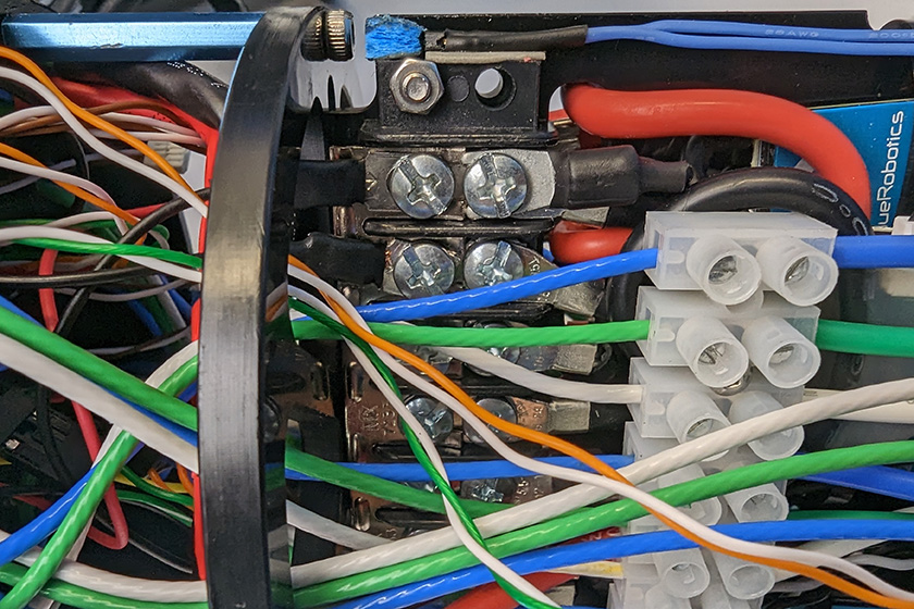
All the black power wires.
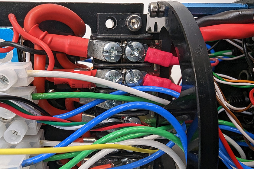
All the red power wires.
Reassemble the Electronics Enclosure
To reassemble the Electronics Enclosure, you will need:
- The M3 mounting screws you removed previously
- Silicone grease (Molykote 111)
- 2.5 mm hex driver
1. Apply a thin coat of silicone grease to the two radial O-rings on the O-ring flange and the inner end of the tube.
2. Reinstall the tube and dome assembly onto the flange. If the ROV has a locking-style enclosure, ensure the rotation locking tab sits inside the slot in the tube.
3. Insert the locking cord through the slot. Older ROVs may not have a locking cord.
4. Reinstall the PRV or vent plug back in the bulkhead. Turn the plug clockwise until it stops to seal it.
5. Place the Electronics Enclosure on the enclosure cradles and line up the mounting clips with the screw holes on the cradles. Use the 2.5 mm hex to install the screws through the mounting clips and into the front and rear enclosure cradles
Mounting the Newton Gripper to the BlueROV2
The Newton Gripper is normally mounted to the BlueROV2 bottom panel, but it can also be mounted to the front of the ROV using the BlueROV2 Roof Rack. The Roof Rack allows the Gripper to be angled up or down, which can be useful when using an attachment like the Newton Gripper Sediment Sampler Attachment. To mount the Gripper using the Roof Rack, follow the instructions in the ‘Mounting the Gripper Using the Roof Rack’ section.
If you have an older BlueROV2, you will need to drill mounting holes in the bottom frame panel before mounting the Gripper. Click on ‘Display drilling instructions’ below to show the instructions for drilling mounting holes. Newer BlueROV2 R4s already have mounting holes so you can proceed directly to mounting the Gripper.
Display drilling instructionsDrilling Mounting Holes
To drill mounting holes, you need:
- 1 x Newton Gripper mount drilling template, included with the kit or download here (8.5 x 11″ or A4 Piece of paper, print setting “Actual”)
- 1 x 5.50 mm (or 7/32″) drill bit (not included)
- Power drill (not included)
1. Cut out and align the template with the bottom frame panel. The Gripper can be mounted on either side of the ROV.
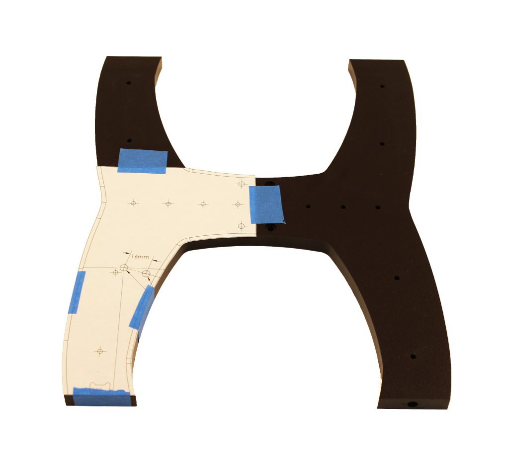
2. With a hand powered drill and 5.50 mm drill bit, drill holes straight through the bottom panel in the indicated positions.
Mounting The Gripper to the Bottom Panel
To mount the Newton Gripper to the BlueROV2 bottom panel, you will need the following parts and tools:
- Newton Gripper mounting clamps and thumbscrew (from Newton Gripper kit)
- 2 x M5x16 Button head screws (from Newton Gripper kit)
- 3 mm Hex driver
- Thread locker
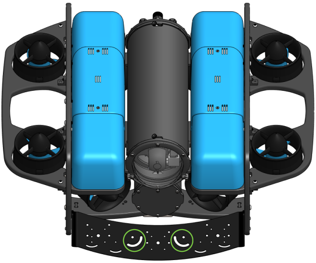
1. Decide on which side of the BlueROV2 you want to install the Gripper. There are two mounting holes in the bottom panel near the front of the ROV on either side of the battery tube.
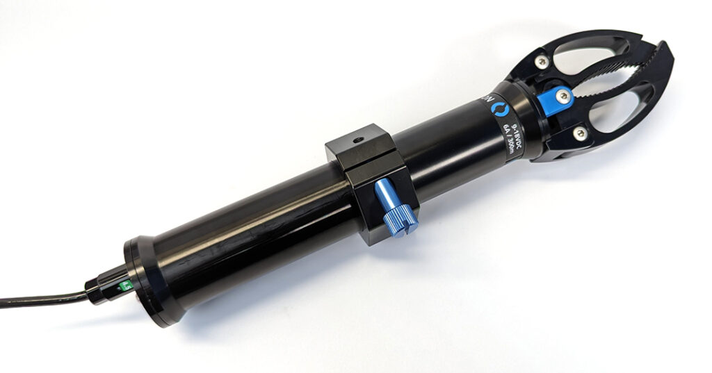
2. Assemble the mounting clamps around the Gripper and use the thumbscrew to secure the two sides together. Orient the mounting clamp so the thumbscrew is facing out and remains accessible from the side you plan on installing the Gripper on.
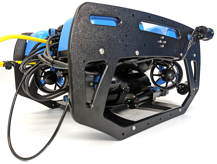
3. Coming from the rear of the BlueROV2, route the Gripper assembly through the frame into its mounting location.
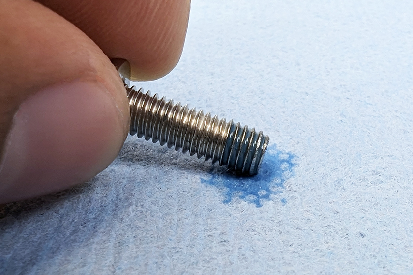
4. Apply a drop of thread locker to the end of the two M5x16 button head screws. Roll the screws on a paper towel to spread the thread locker evenly and remove excess.
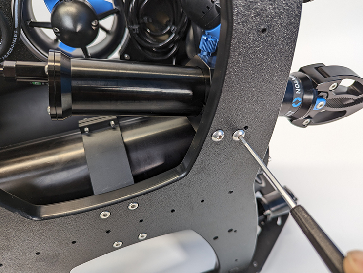
5. Use the M5x16 screws and 3 mm hex to mount the Gripper to the bottom frame panel.
Mounting the Gripper Using the Roof Rack
The Roof Rack allows the Gripper to be mounted in front of the ROV and angled up or down, which can be useful when using an attachment like the Newton Gripper Sediment Sampler Attachment. To mount the Gripper using the Roof Rack, you will need:
- 1 x BlueROV2 Roof Rack (sold separately)
- 2 x M5-0.8×7 screw (not included)
- 3 mm hex driver
- Thread locker
1. Install the Roof Rack following the instructions for front mounting the Roof Rack.
2. Assemble the mounting clamps around the Gripper and use the thumbscrew to secure the two sides together.
3. Apply a drop of thread locker to the end of the two M5x7 button head screws. Roll the screws on a paper towel to spread the thread locker evenly and remove excess.
4. Use the M5x7 screws and 3 mm hex to mount the Gripper to the Roof Rack. The Gripper can be mounted to either of these mounting locations:
The angle of the Roof Rack can be adjusted within the mounting slot.
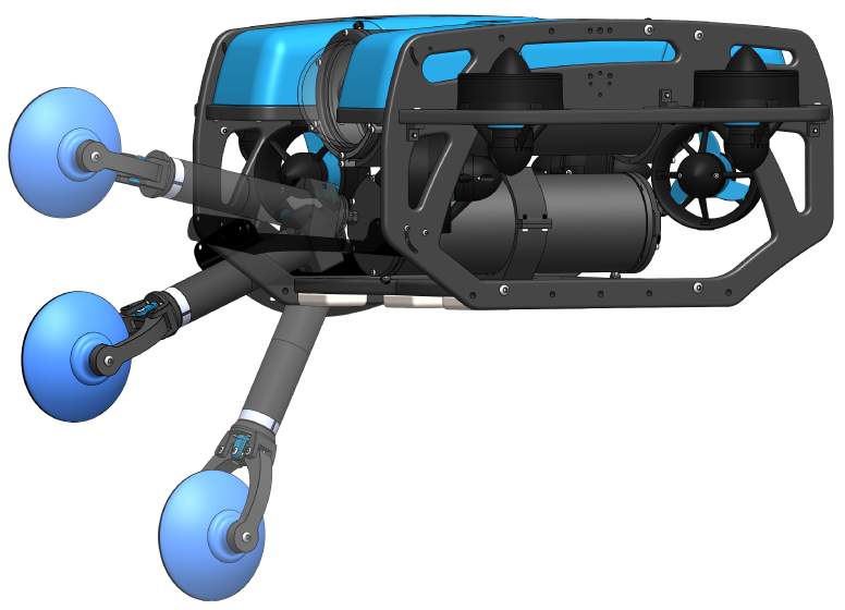
Newton Gripper with Sediment Sampler Attachment shown.
Cable Management
The goal of good cable management is to secure the cable to the ROV frame to prevent it from getting damaged by the thruster propellers or getting caught on something during operation. Before securing the cable, make sure you have enough slack in the cable by fully retracting and extending the Gripper in the mounting bracket. Secure the cable to the frame using the included cable ties so there is no loose cable. Make sure to check that the cable cannot reach a thruster propeller after you have finished.
Adjusting the Ballast on the Frame
The Gripper adds some weight to the BlueROV2 frame so the ROV ballast will need to adjusted to keep it neutrally buoyant and balanced in the water. Remove or relocate the ballast weights on the bottom of the frame to adjust the ballast. You can view complete instructions for adjusting the ballast in the ‘Servicing the BlueROV2’ section of the BlueROV2 Operation guide.
Setup in BlueOS
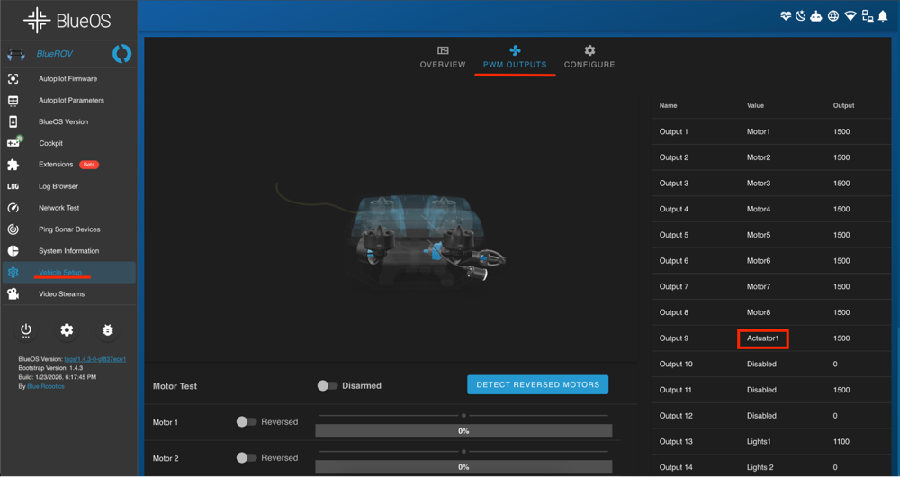
1. In the latest stable version of BlueOS navigate to Vehicle Setup.
2. Select PWM Outputs.
3. Find the output you have wired the gripper to (for example Output 9).
4.Change that Output’s function to ActuatorN, where N is the actuator number you want to assign to the gripper. For example if you select Actuator1 for Output 9 then that output becomes Actuator1.
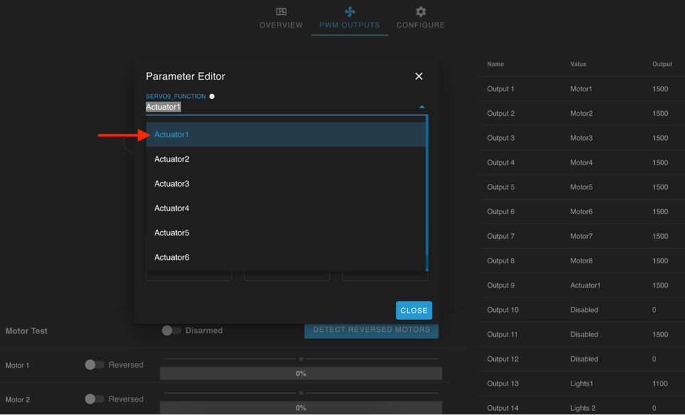
5. Close the Parameter Editor menu to save your changes.
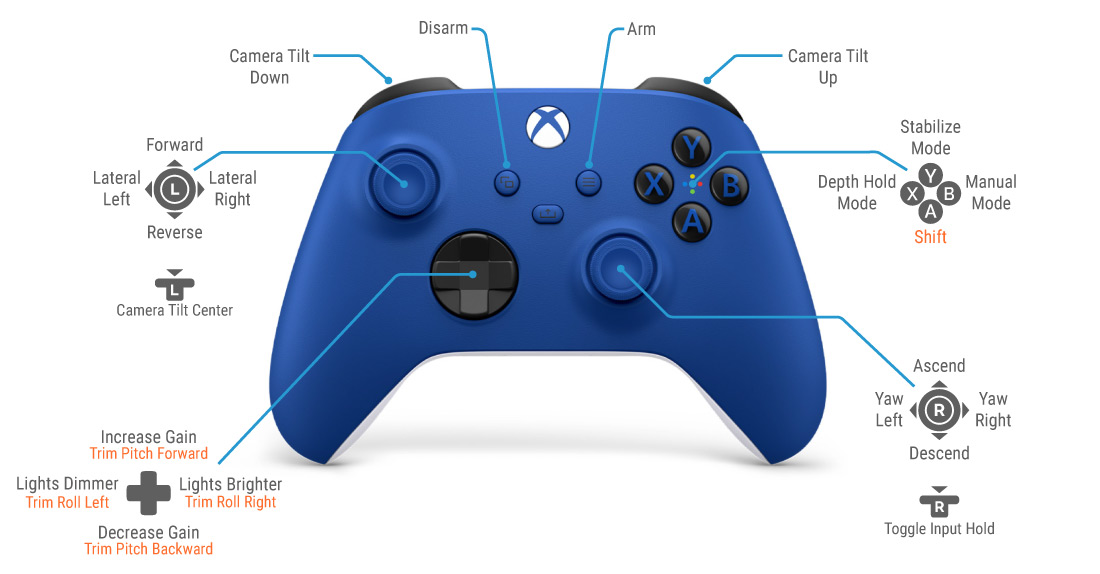
Setup Gripper Control
You will have to add the actuator button functions to your controller layout to use the Gripper. Our preference is to assign the Gripper open and close functions to the shoulder bumper buttons (the camera tilt buttons) then move camera tilt functions to the shift layer, but you can set up your layout however you like.
You can configure the gripper behavior in the following ways, using the same actuator number selected in BlueOS:
| Action | Cockpit Label | QGroundControl Label |
|---|---|---|
| Open the Gripper fully | Actuator N Max | servo_N_max |
| Close the Gripper fully | Actuator N Min | servo_N_min |
| Open the Gripper only while the button is held | Actuator N Max Momentary | servo_N_max momentary |
| Close the Gripper only while the button is held | Actuator N Min Momentary | servo_N_min momentary |
Gripper control in Cockpit
1. Open Cockpit and connect to your vehicle.
2. Go to the Joystick settings menu.
3. Locate the button you want to use to control the gripper.
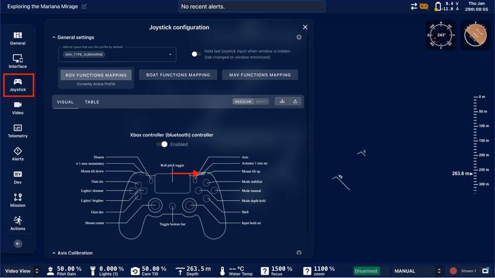

Close the Input Mapping and the Joystick Configuration menus to save Configuration changes.
Gripper control in QGroundControl
QGroundControl refers to actuators as servos. The Newton Subsea Gripper can be controlled in QGroundControl by assigning the appropriate servo functions to joystick buttons.
1. Connect to the vehicle in QGroundControl.
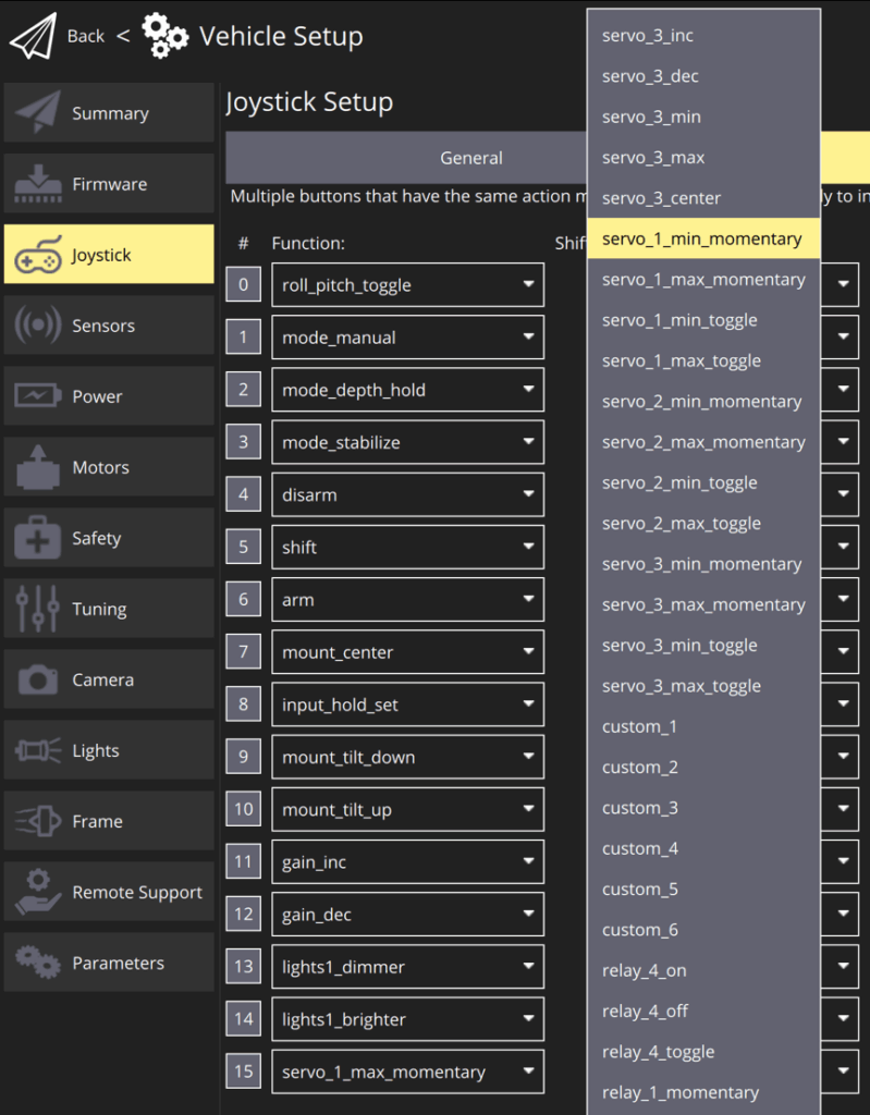
2. Open Vehicle Setup and go to Joystick and select Button Assignment.
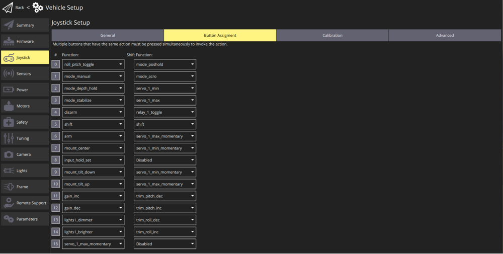
3. Locate the button you want to use to control the gripper.
4. Close the Joystick and the Vehicle Configuration menus to save Configuration changes.
Final Test
That’s it! Once the BlueROV2 is powered up you should be able to control the Gripper with the joystick buttons. The ROV does not need to be armed for the Gripper to be active.
To deploy the Newton Gripper, loosen the thumbscrew and extend the Gripper from the mount then tighten the thumbscrew again. To store the Gripper, loosen the thumbscrew and retract the Gripper.
We’re always working to make our documentation, instructions, software, and user experience even better. If you have any ideas on how we can improve this guide, feel free to let us know here.