
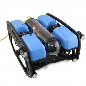
BlueROV2 Assembly (R1 and R2 Versions)
Guide Versions
This assembly guide is for the R1 and R2 version of the BlueROV2. There are three versions of the BlueROV2 assembly guide that each reflect the major revisions to the BlueROV2 hardware and assembly process. Please ensure you are viewing the correct assembly guide for the revision of BlueROV2 you have. The revision number for your BlueROV2 can be found in the product SKU in your order information (example: “BLUEROV2-M-R4-RP”).
R4 Version (with Navigator Flight Controller, sold from 7 June 2022 to present): use the BlueROV2 Assembly Guide
R3 Version (with Pixhawk autopilot and dual power cables, sold from 14 September 2021 to 6 June 2022): use the BlueROV2 R3 Assembly Guide
R1 and R2 Version (with Pixhawk autopilot and single power cable, sold from 21 June 2016 to 13 September 2021): continue using this guide
Guides in this Series
BlueROV2 Assembly (R1 and R2 Versions)
BlueROV2 Software Setup (R3 and Older)
BlueROV2 Operation
Introduction
The BlueROV2 kit comes almost ready to dive. The assembly can be completed with basic hand tools; no soldering or potting is required. We have included a couple of the tools to make assembly and regular use as easy as possible.
The assembly process will differ depending on whether you are assembling a standard BlueROV2 or a BlueROV2 with the optional BlueROV2 Heavy Configuration Retrofit Kit. Select the type of kit you are assembling below. If you are assembling a new BlueROV2 without a Heavy Kit, select “BlueROV2”. If you are assembling a new BlueROV2 with an optional Heavy Kit, select “BlueROV2 Heavy Configuration”.
If you are retrofitting a Heavy Kit onto a fully assembled BlueROV2, please use the BlueROV2 Heavy Configuration Retrofit Kit Installation guide instead.
BlueROV2BlueROV2 Heavy ConfigurationSafety
Parts and Tools
You Will Need
-
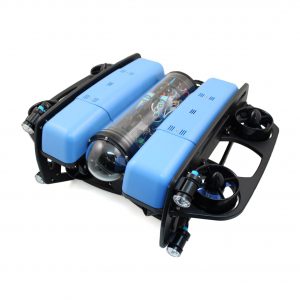
BlueROV2
Affordable and customizable high-performance ROVFrom: $ 4,900.00 -
BlueROV2 Heavy Kit
Add-on kit for improved stability and maneuverability$900.00 -
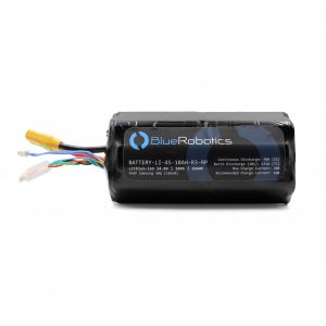
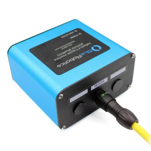
Lithium-ion Battery (14.8V, 18Ah)
High-power lithium-ion battery for the BlueBoat and BlueROV2$425.00 -
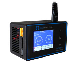
H6 PRO Lithium Battery Charger
10A charger for lithium-ion batteries$196.00
You will also need (not included with kit):
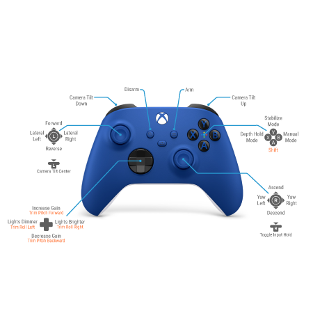
- 1 x Gamepad controller. We recommend this XBox One Controller (finer control) or this Logitech Gamepad (more affordable).
- 1 x Laptop or a Windows 10 tablet with 8GB of RAM or higher. The topside control software, QGroundControl, works on Mac, Windows 10 (i5 processor), and Linux.
- 1 x Wire cutters or scissors (for cutting zip ties)
- 1 x Medium-strength (blue) threadlocker such as Loctite 243
- 1 x Bottle of Isopropyl alcohol or isopropyl alcohol wipes
- 1 x Small (~2 mm) flat head screw driver
- 1x Heat gun or hairdryer or lighter (for heating heat shrink)
Assembling the Frame
Mounting the Battery Enclosure to the Bottom Panel
To mount the battery enclosure to the bottom panel you will need the following parts and tools:
- 2 x Enclosure Clamp (3″ Series)
- 1 x Threadlocker
- 1 x Bottom panel
- 1 x Bag with four M4x14 socket head cap screws and four M3x12 socket head cap screws
- 1 x Watertight Enclosure for ROV/AUV (3″ Series)
- 1 x 3 mm hex key
- 1 x 2.5 mm hex driver
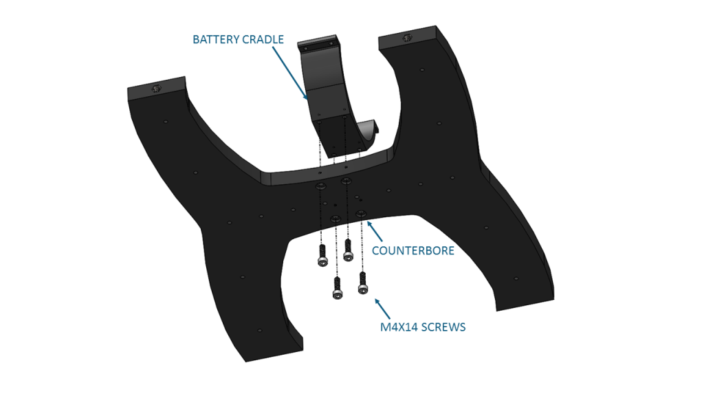
1. Remove the Aluminum End Cap with 4 Holes (3″ Series) to open the Watertight Enclosure for ROV/AUV (3″ Series) and set the bags inside of it to the side.
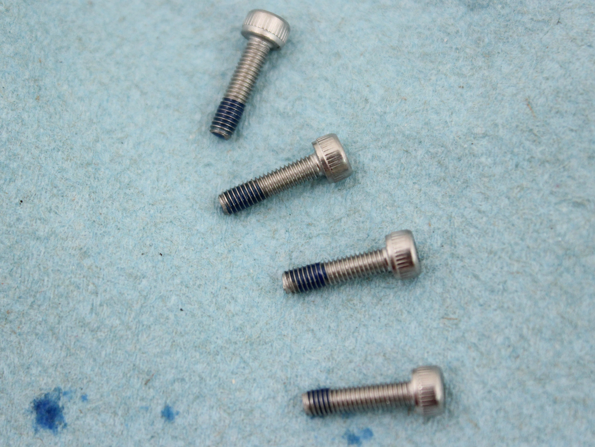
2. The bag with four M4x14 and four M3x12 screws in it will be packaged with the Enclosure Clamp (3″ Series). Apply one drop of threadlocker to the bottom of each M4x14 socket head cap screw. Roll the screws around on a paper towel to evenly spread the threadlocker and to remove excess threadlocker.
3. The Enclosure Clamp (3″ series) includes an extra pair of thicker adhesive rubber strips for mounting optional aluminum tubes that have a smaller outer diameter. If you are using a Watertight Enclosure for ROV/AUV (3″ Series) with an aluminum tube, remove the existing rubber strips from the Enclosure Clamp (3″ series) and use the thicker adhesive rubber strips instead.
4. Attach one of the Enclosure Clamps (3″ Series) to the bottom panel using the four M4x14 socket head cap screws. Be sure that the screw head is in the counterbore. The bottom panel is only counterbored on one side. Tighten the screws until you can feel them start to dig into the bottom panel.
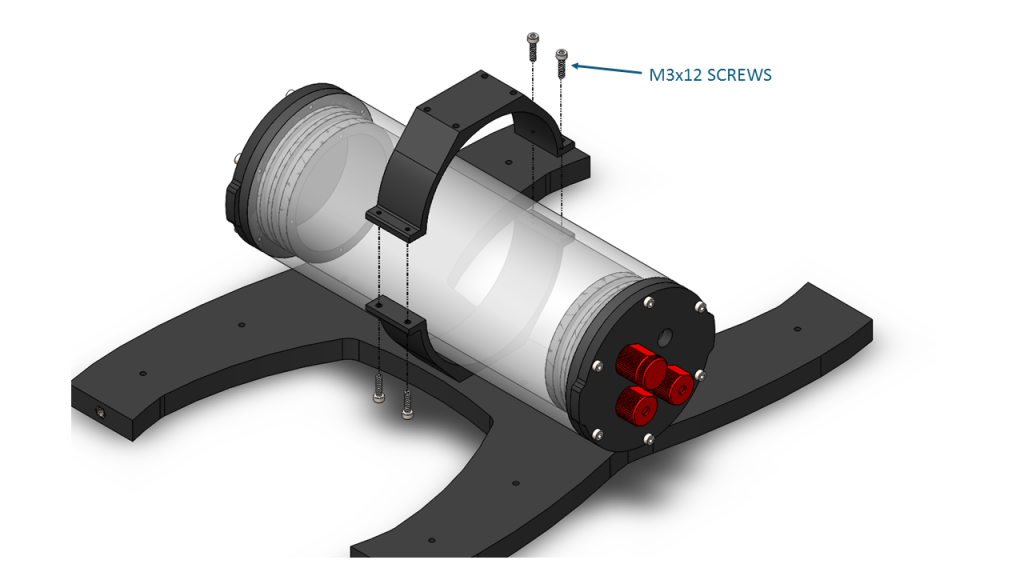
5. Apply one drop of threadlocker to each of the 4 M3x12 screws. Roll the screws around on a paper towel to evenly spread the threadlocker and to remove excess threadlocker.
6. Place the Watertight Enclosure for ROV/AUV (3″ Series) between the two Enclosure Clamps (3″ Series). The Enclosure Clamps have tapped holes on one side and untapped holes on the other.
7. Install the four M3x12 screws into the Enclosure Clamps (3″ Series) so that the screws pass through the untapped holes on the first clamp and are secured into the tapped holes on the alternate clamp. Install all four screws loosely at first and then slowly tighten them on both sides evenly. Take care not to overtighten the screws. Keep the battery enclosure approximately centered in the Enclosure Clamps (3″ Series).
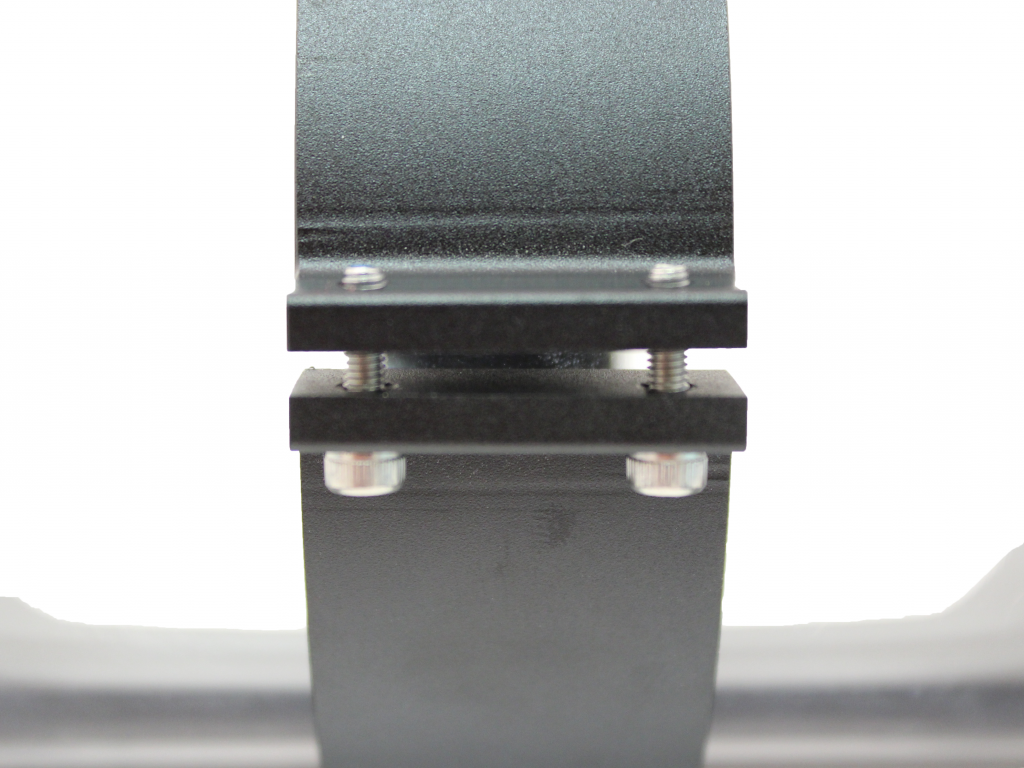
8. When you are finished tightening the screws, both sides should look similar to this.
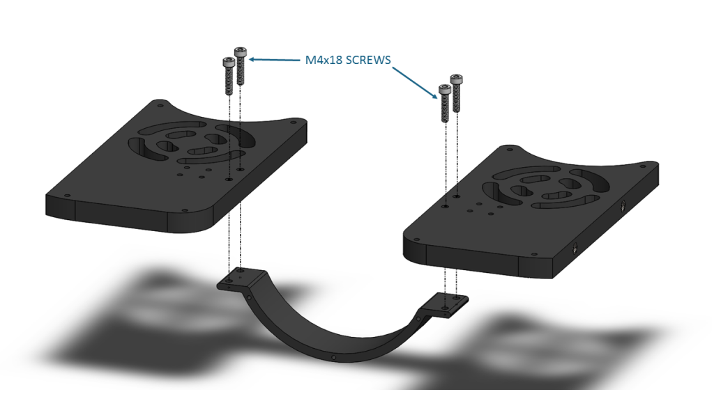
Assembling the Center Panels
To assemble the center panels you will need the following parts and tools:
- 2 x Enclosure Cradle (4″ Series)
- 2 x Front center panels
- 2 x Rear center panels
- 1 x Threadlocker
- 1 x Bag with eight M4x18 socket head cap screws
- 1 x 3 mm hex key
1. Apply one drop of threadlocker to each of the eight M4x18 screws. Roll the screws around on a paper towel to evenly spread the threadlocker and to remove excess threadlocker.
2. Attach one of the Enclosure Cradle (4″ Series) to the rear center panels. Tighten the screws until they indent the rear center panels slightly.
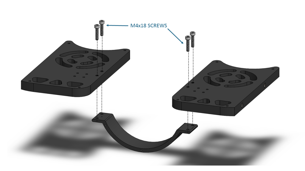
3. Attach the other Enclosure Cradle (4″ Series) to the front center panels. Tighten the screws until they indent the front center panels slightly.
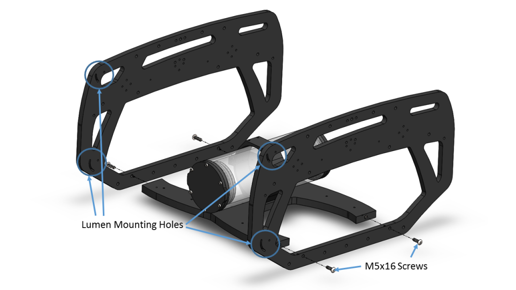
Assembling the Frame
To assemble the frame you will need the following parts and tools:
- 1 x Threadlocker
- 1 x Bag with 12 M5x16 button head cap screws
- 2 x Side panels
- 1 x Bottom panel with the Watertight Enclosure for ROV/AUV (3″ Series) installed
- 1 x Front center panel assembly
- 1 x Rear center panel assembly
- 1 x 3 mm hex key
1. Apply one drop of threadlocker to each of the 12 M5x16 screws. Roll the screws around on a paper towel to evenly spread the threadlocker and to remove excess threadlocker.
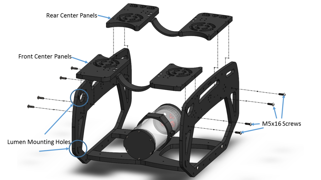
2. Install both side panels to the bottom panel using four of the M5x16 screws; the Aluminum End Cap (3″ Series) on the Watertight Enclosure for ROV/AUV (3″ Series) should be on the same side as the Lumen mounting holes. It is very important to avoid overtightening these screws. Tighten these screws using the provided 3 mm hex key. Hold the short end of the 3 mm hex key while you are tightening the M5x16 screws. Do not tighten beyond the tightness you can achieve holding the short end of the 3 mm hex key.
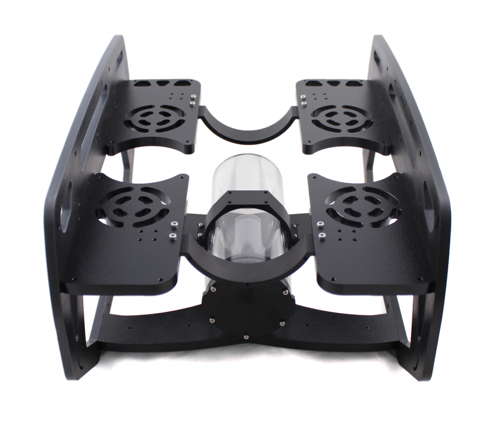
3. Install the center panel assemblies to the side panels using the remaining eight M5x16 screws. It is very important to avoid overtightening these screws. Tighten these screws using the provided 3 mm hex key. Hold the short end of the 3 mm hex key while you are tightening the M5x16 screws. Do not tighten beyond the tightness you can achieve holding the short end of the 3 mm hex key.
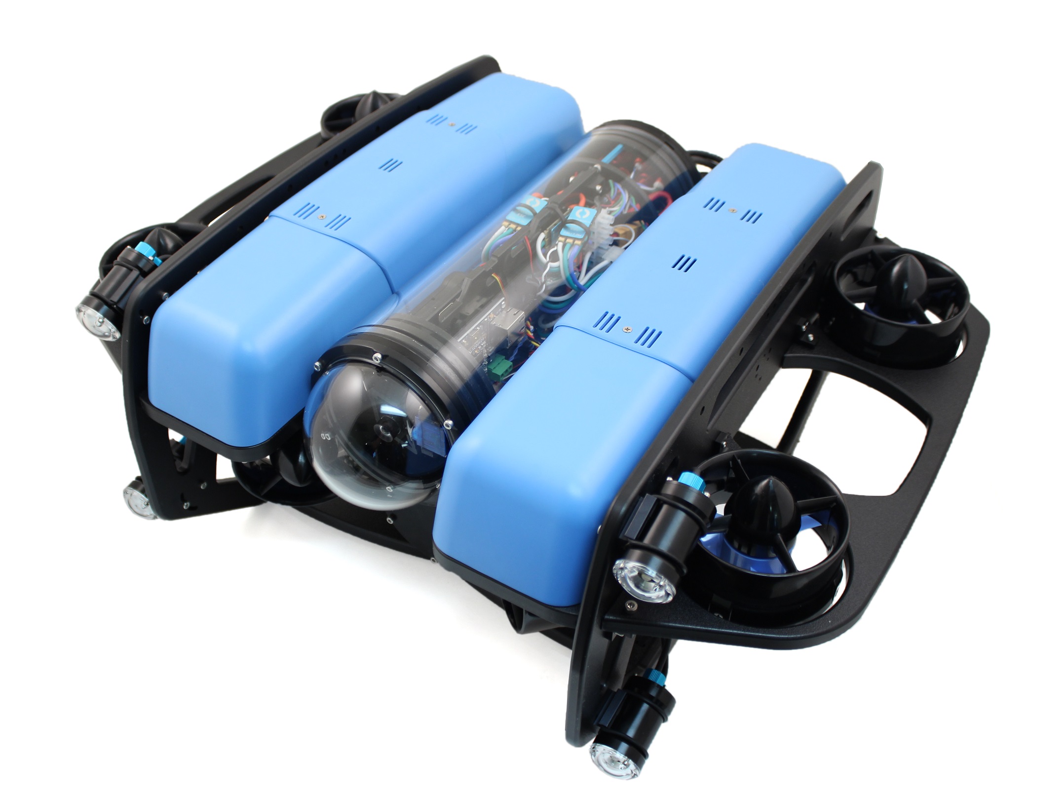
Now the BlueROV2 should look like the picture below.
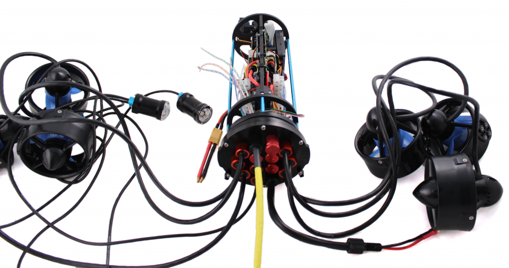
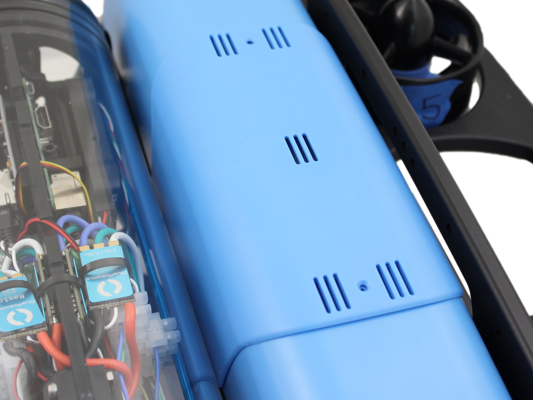
Electronics Enclosure Overview
The images below show orientation of the main pieces of hardware in the electronics enclosure. They also point out the names of several of the important parts for assembly that will be discussed in the remaining instructions.
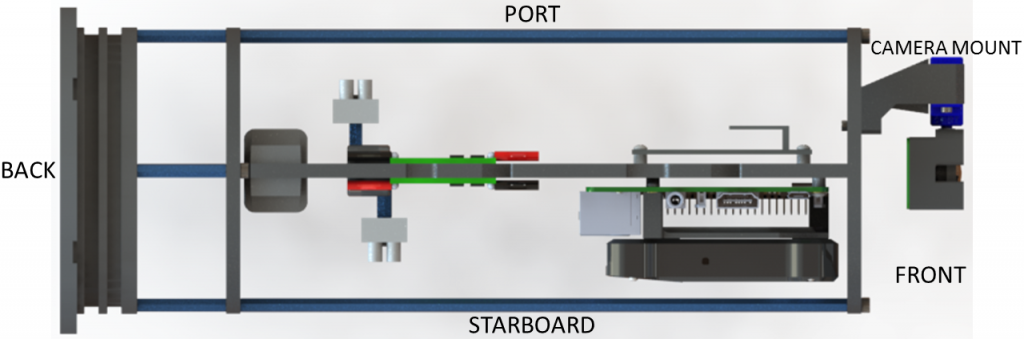
Top View
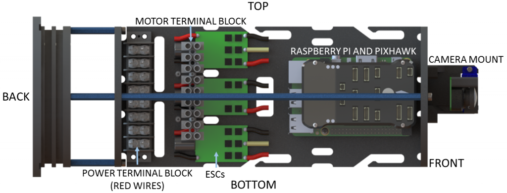
Starboard View
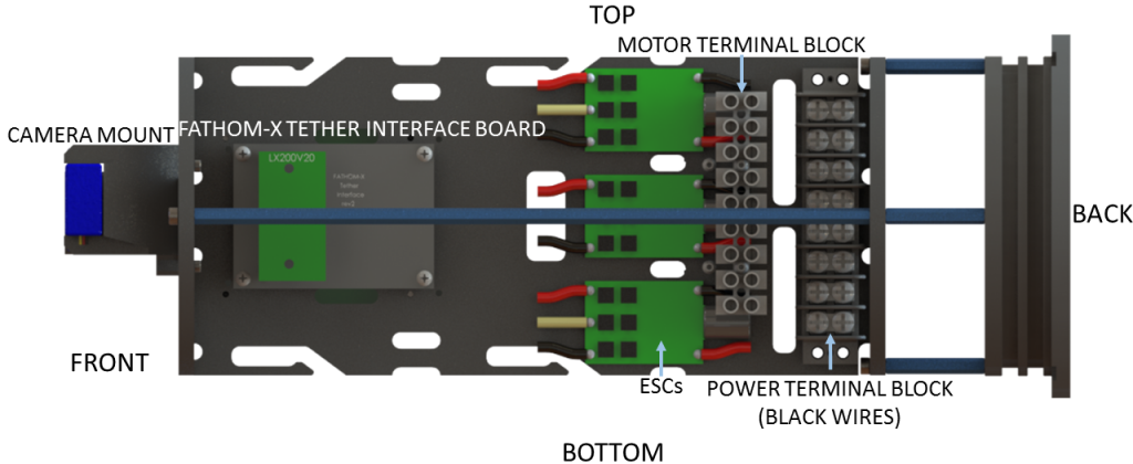
Port View
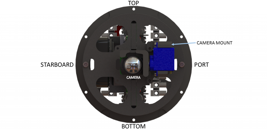
Front View
Connection Diagrams
These diagrams outline all of the electrical connections between components in the ROV. There is a different diagram for each version of the ROV that Blue Robotics has produced.
- BlueROV2 with red-wire (BEC) ESCs (Pre-2018)
- BlueROV2 with no-red-wire ESCs (2018 and later)
- BlueROV2 Heavy
Installing the Cables
Removing the Electronics Enclosure Endcap
The endcap will need to be removed from the electronics enclosure in order to install the cable penetrators. To remove the endcap you will need the following parts and tools:
- 1 x Large flat head screw driver (Optional)
- 1 x The electronics enclosure assembly
- 1 x 2.5 mm key driver
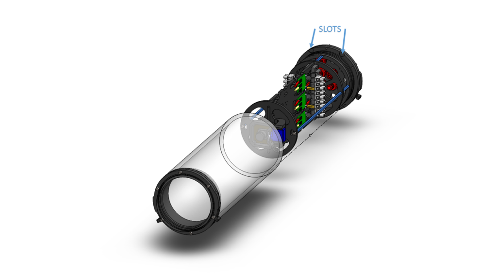
1. Remove the Watertight Enclosure for ROV/AUV with Dome End Cap installed from the rear O-Ring Flange (4″ Series). If this step is difficult, you can place a large flat head screwdriver into the slots on the O-Ring Flange (4″ Series), and then twist to get a gap between the acrylic tube and the O-Ring Flange (4″ Series). Once you have the gap, you can wedge a screw driver between the end of the acrylic tube and the O-Ring Flange (4″ Series) to finish removing the acrylic tube.
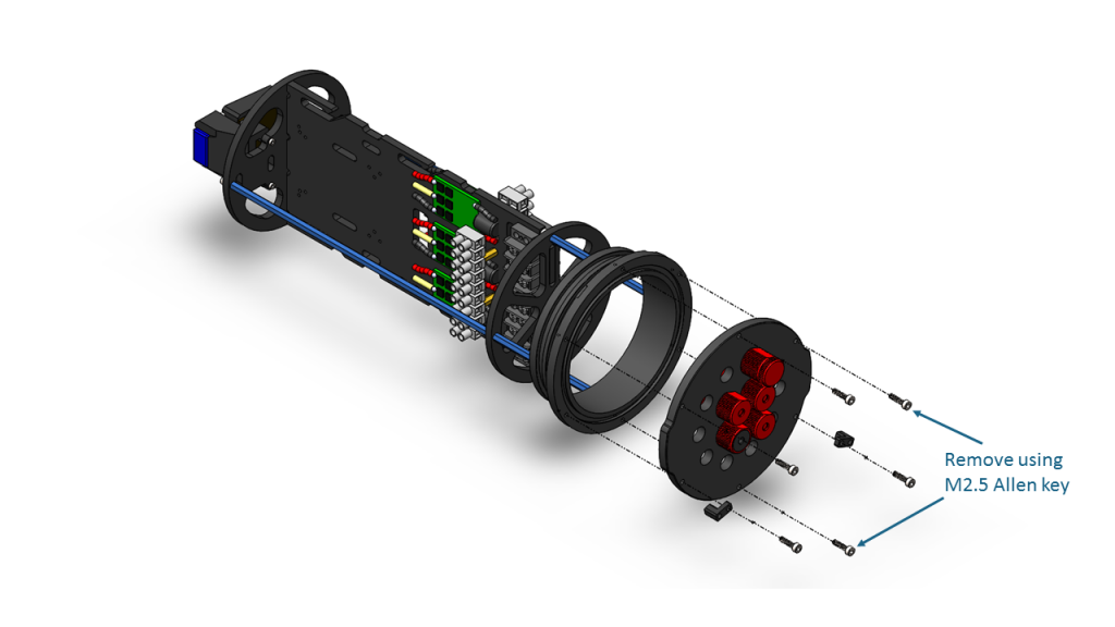
2. Remove the Aluminum End Cap with 14 Holes by removing the six M3x12 screws using the M2.5 hex driver. Place the M3x12 screws, extensions (small L-shaped parts), and face seal O-ring in a safe place.
Installing the Penetrators
To install the Penetrators you will need the following parts and tools:
- 1 x Cable Penetrator Nut (Black for Standard Tether/Red for Slim Tether), and O-ring from one end of the Tether
- 6 x Cable Penetrator Nut (red), and O-ring from bag inside each Thruster tube packages
- (Optional if no Lumens) 1 x Cable Penetrator Nut (red) and O-ring from spares bag
- 1 x Silicone Grease – 10g Tube
- 1 x Aluminum End Cap with 14 Holes w/ 3 Cable Penetrator Blanks, 1 Bar30 Pressure Sensor, 1 Enclosure Vent and Plug, and 1 power cable installed
- 3 x T200 with counter-clockwise propeller
- 3 x T200 with clockwise propeller
- 1 x Set of Lumen lights (optional)
- 1 x Fathom ROV Tether
- 1 x Penetrator Wrench
- 1 x Cable Penetrator Nut (Black for Standard Tether/Red for Slim Tether), and O-ring from one end of the Tether
- 8 x Cable Penetrator Nut (red), and O-ring from bag inside each Thruster tube packages
- (Optional if no Lumens) 1 x Cable Penetrator Nut (red) and O-ring from spares bag
- 1 x Silicone Grease – 10g Tube
- 1 x Aluminum End Cap with 14 Holes w/ 3 Cable Penetrator Blanks, 1 Bar30 Pressure Sensor, 1 Enclosure Vent and Plug, and 1 power cable installed
- 4 x T200 with counter-clockwise propeller (one will be from the Heavy Retrofit Kit)
- 4 x T200 with clockwise propeller (one will be from the Heavy Retrofit Kit)
- 1 x Set of Lumen lights (optional)
- 1 x Fathom ROV Tether
- 1 x Penetrator Wrench
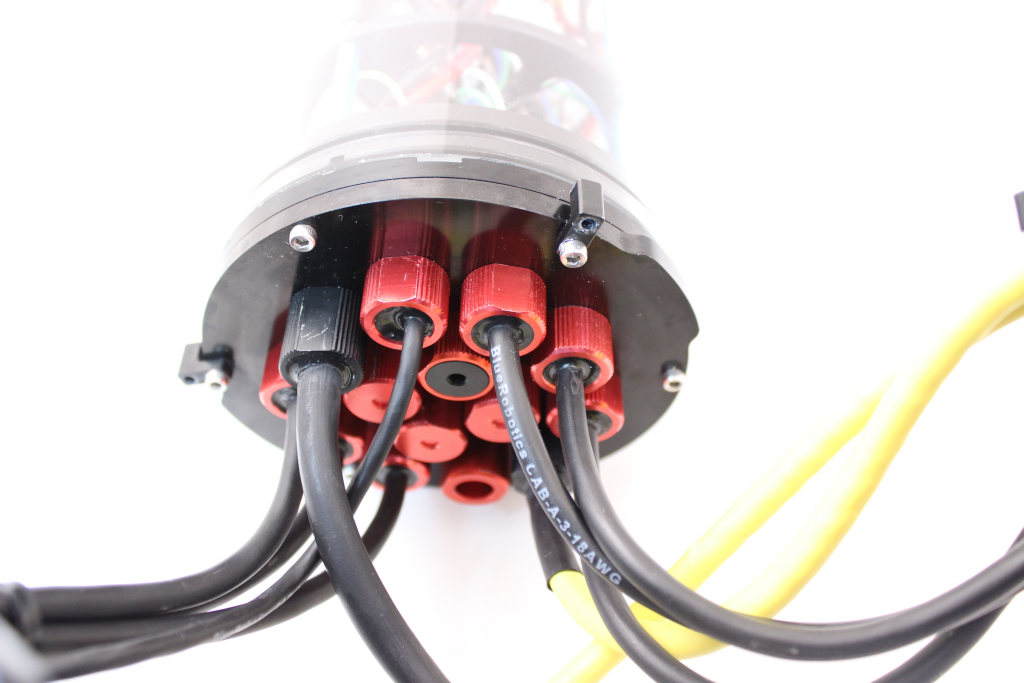
The Aluminum End Cap with 14 Holes comes with 3 Cable Penetrator Blanks, 1 Bar30 Pressure Sensor, 1 Enclosure Vent and Plug, and 1 power cable installed.
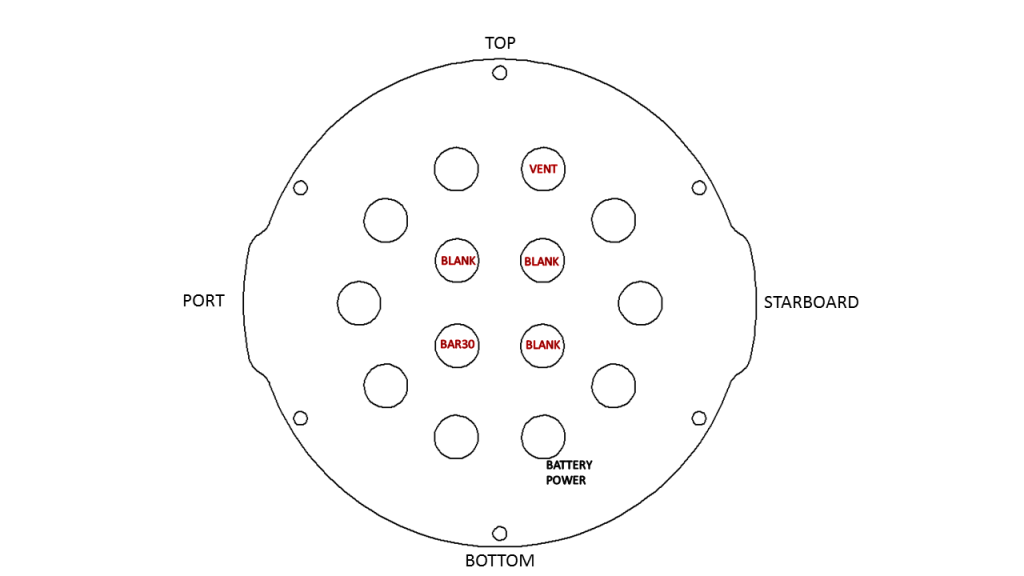
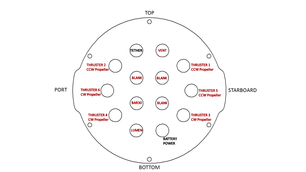
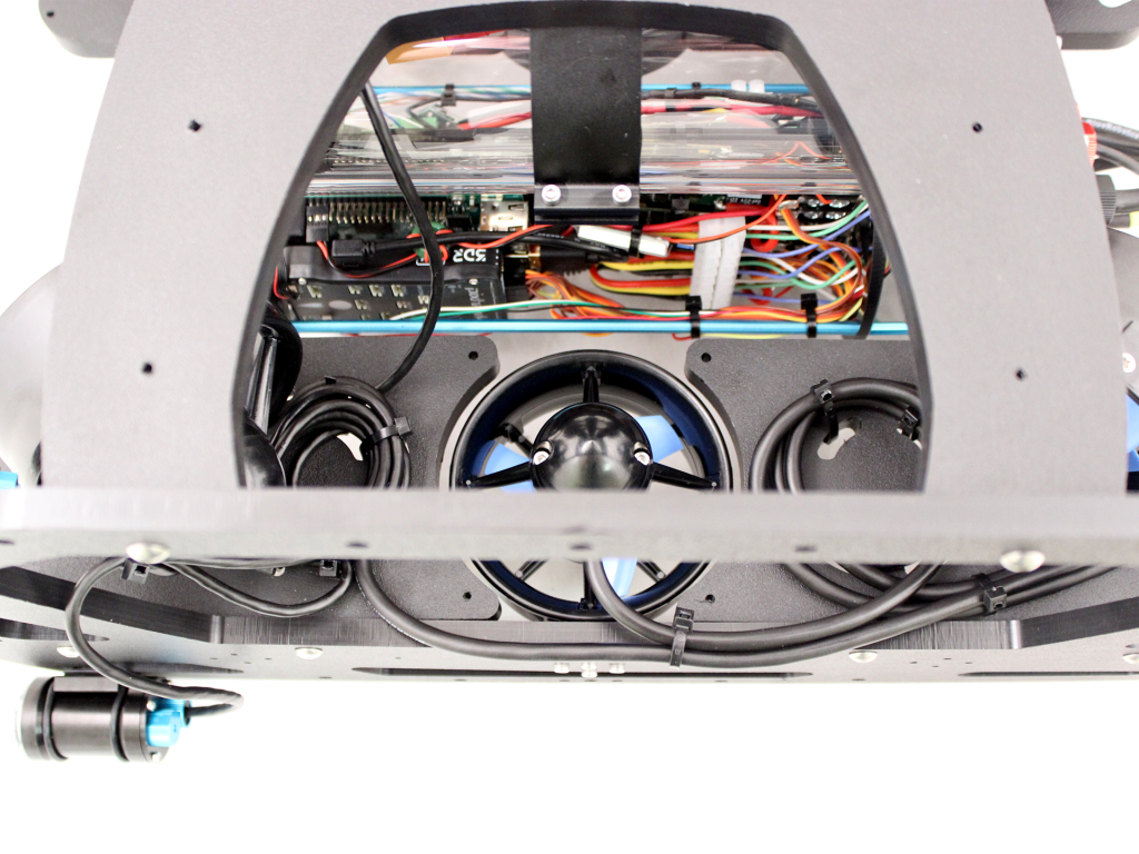
If you install the remaining penetrators as shown in the diagram below, it will keep everything neat and organized.
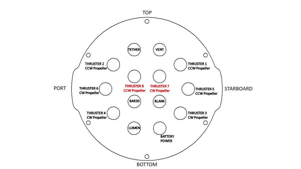
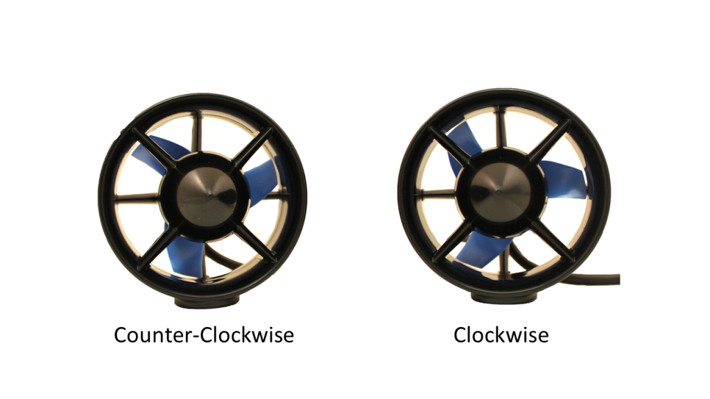
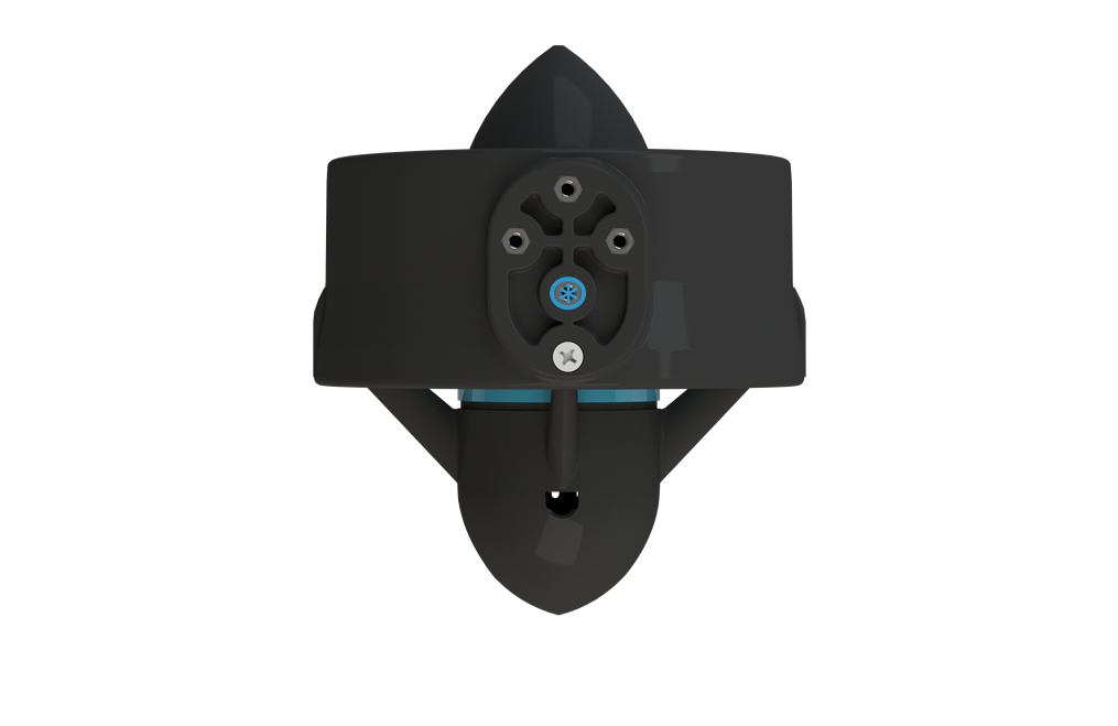
If the thrusters are removed from the containers and not marked, the image below will help determine orientation.
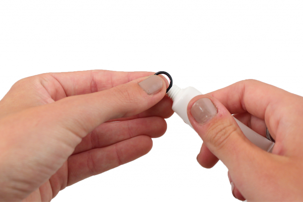
1. Remove eight of the O-rings and apply silicone grease to them. Keep the other O-ring in the bag, you will need it in a minute.
2. Wipe the exterior surface of the electronics enclosure endcap clean with isopropyl alcohol or isopropyl alcohol wipes, and make sure it is free of any particles in the areas where the penetrator O-rings will sit.
3. Install the O-rings onto all of the thruster penetrators, the lumen penetrator, and the tether penetrator.
4. Install the penetrators to the end cap in the order shown below. Tighten to finger tight, then use the provided wrench to tighten them an additional ~1/16 of a turn. If you can’t loosen them with your fingers, they are tight enough.
1. Thruster 1 (CCW propeller) with red penetrator nut
2. Thruster 5 (CCW propeller) with red penetrator nut
3. Thruster 3 (CW propeller) with red penetrator nut
4. Lumen with red penetrator nut (or Blank Penetrator (red) if not installing Lumens)
5. Thruster 4 (CW propeller) with red penetrator nut
6. Thruster 6 (CW propeller) with red penetrator nut
7. Thruster 2 (CCW propeller) with red penetrator nut
8. Tether with black penetrator nut (standard Tether) or red penetrator nut (Slim Tether)
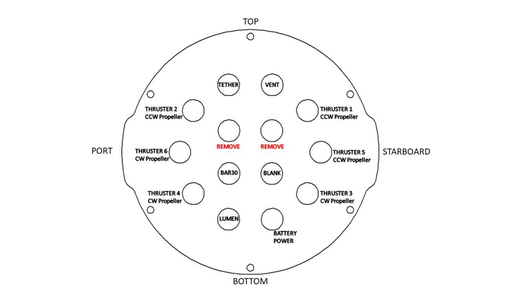
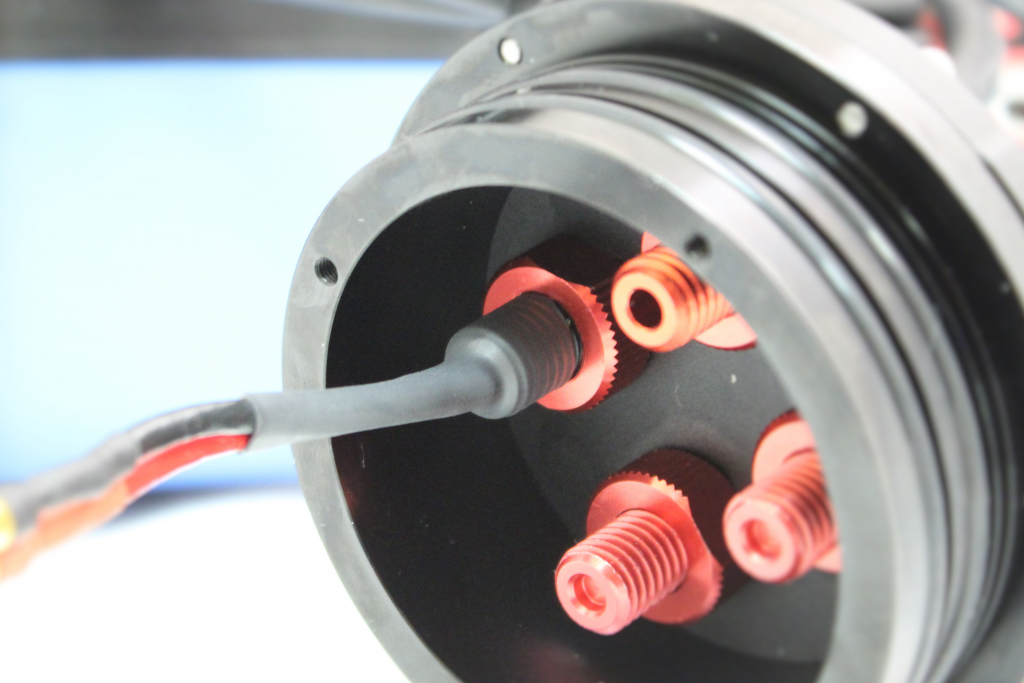
1. Remove the two blank penetrators as pictured from the 4” End Cap with the penetrator wrench that came with the BlueROV2 kit.
2. Remove ten of the O-rings and apply silicone grease to them. Keep the other O-ring in the bag, you will need it in a minute.
3. Wipe the exterior surface of the electronics enclosure endcap clean with isopropyl alcohol or isopropyl alcohol wipes, and make sure it is free of any particles in the areas where the penetrator O-rings will sit.
4. Install the O-rings onto all of the thruster penetrators, the lumen penetrator, and the tether penetrator.
5. Install the penetrators to the end cap in the order shown below. Tighten to finger tight, then use the provided wrench to tighten them an additional ~1/16 of a turn. If you can’t loosen them with your fingers, they are tight enough. Optional: In order to ensure thruster mounting is not mixed up, it is recommended to apply short strips of masking tape to the outside of the thruster ducts and labeling them according to the thruster number.
1. Thruster 7 (CW propeller) with red penetrator nut
2. Thruster 1 (CCW propeller) with red penetrator nut
3. Thruster 5 (CCW propeller) with red penetrator nut
4. Thruster 3 (CW propeller) with red penetrator nut
5. Lumen with red penetrator nut (or Blank Penetrator (red) if not installing Lumens)
6. Thruster 8 (CCW propeller) with red penetrator nut.
7. Thruster 4 (CW propeller) with red penetrator nut
8. Thruster 6 (CW propeller) with red penetrator nut
9. Thruster 2 (CCW propeller) with red penetrator nut
10. Tether with black penetrator nut (standard Tether) or red penetrator nut (Slim Tether)
Installing the End Cap
To reinstall the Aluminum End Cap with 14 Holes you will need the following parts and tools:
- The face seal O-ring, the 6 M3x12 screws, and the extensions that you removed from the end cap earlier
- 1 x Silicone Grease – 10g Tube
- 1 x Aluminum End Cap with 14 Holes with all Cable Penetrators and Blank Penetrators installed
- 1 x 2.5 mm hex driver
1. Clean the O-ring and make sure that it is free of any debris or damage.
2. Clean the O-Ring Flange (4″ Series) and make sure that the O-ring groove is free of any debris or damage.
3. Apply Silicone grease to the O-ring.
4. Install face seal O-ring onto the O-Ring Flange (4″ Series).
5. Apply one drop of threadlocker to each of the M3x12 screws. Roll the screws around on a paper towel to evenly spread the threadlocker and to remove excess threadlocker.
6. Install Aluminum End Cap with 14 Holes with all Cable Penetrators and Blank Penetrators installed onto the O-Ring Flange (4″ Series). Do not fully tighten any screws when first installing them; it may cause the O-ring to slip out of its groove. The end cap’s orientation when installed should match the image below. Make sure that the extensions are oriented correctly. One should be just right of the Thruster 3 penetrator, and the other should be just left of the Thruster 4 penetrator.
Finishing the Battery Enclosure
To complete the assembly of the battery enclosure you need the following parts and tools:
- 1 x Bag labeled “Extra Blank Penetrators [2]”
- 1 x Silicone Grease – 10g Tube
- 1 x End Cap with 4 Holes (3″ Series)
- 1 x Penetrator wrench
- 1 x XT90 to 3.5 mm bullet connector adapter
- 1 x 1.5 inch piece of heat shrink
- 1 x Heat gun, hairdryer, or lighter
1. Apply silicone grease to the O-ring.
2. Install the O-ring onto the battery power cable penetrator.
3. Install the battery power cable penetrator into the opening in the battery end cap.
4. Install one Cable Penetrator Nut (Red) on to the battery power cable penetrator and tighten with penetrator wrench.
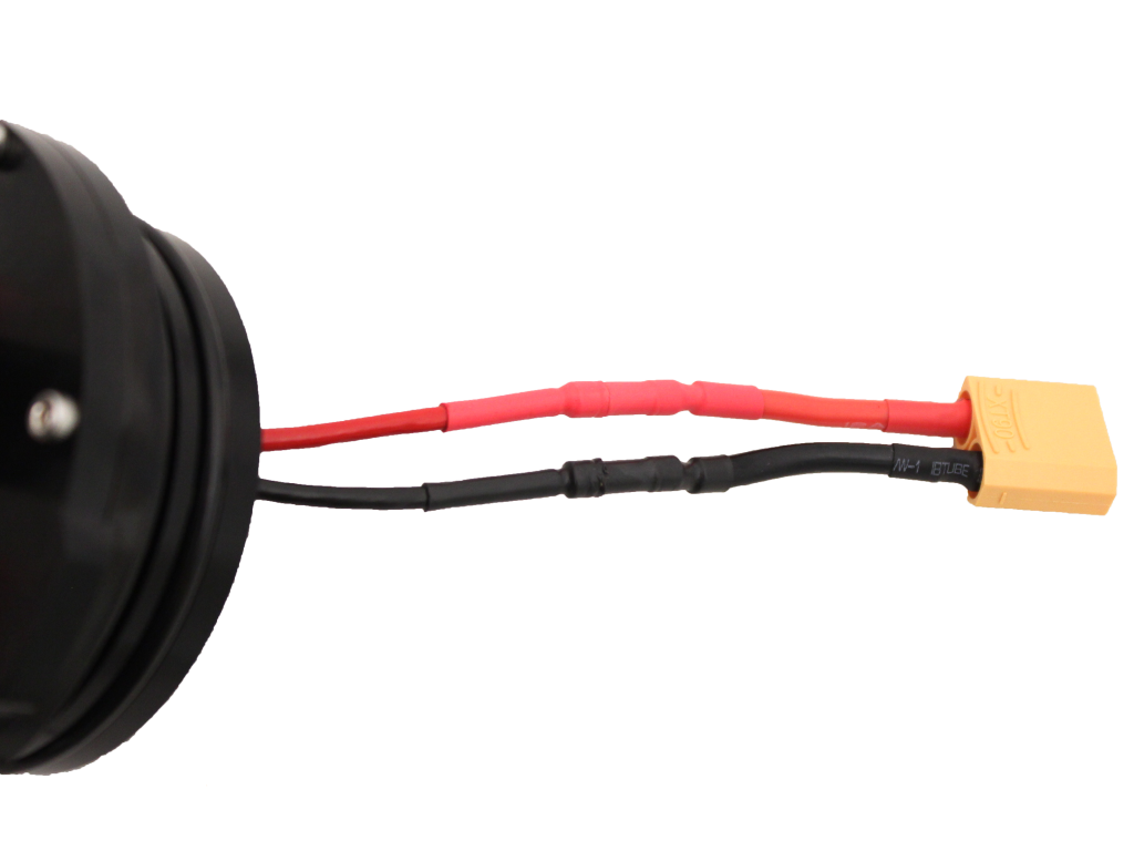
5. Place the 1.5 inch long piece of black heat shrink over the end of the battery power cable penetrator.
6. Apply heat to the heat shrink using your heat gun, hairdryer, or lighter until the heat shrink is firmly attached to the penetrator and snug to the two wires. You should be able to see the threads in the penetrator through the heat shrink.
7. Install the XT90 to bullet connector adapter to the battery power wire.
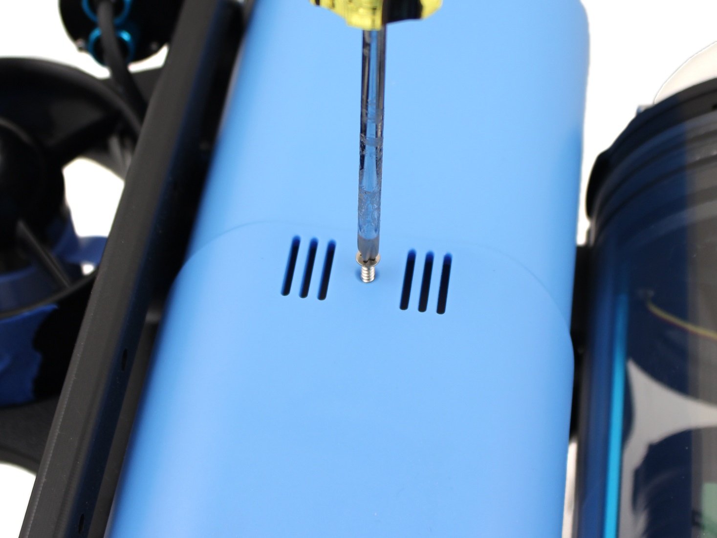
8. If you wish to do the Optional Preliminary Vacuum Test, remove the Vent Plug from the Vent Penetrator Bolt and install the endcap onto the battery enclosure. You will also need to remove the Vent Plug for the Vent Penetrator Bolt on the electronics enclosure.
Optional Preliminary Vacuum Test
This is the best point in the assembly process to perform a vacuum test. Since you have installed all of the penetrators, but have not done any of the wiring, troubleshooting will be as easy as possible. You will need to use the vacuum pump that comes with the kit.
1. Install the Watertight Enclosure (4″ Series) with installed Dome onto the O-Ring Flange (4″ Series) that is attached to the Aluminum End Cap with 14 Holes (4″ Series)
2. Assemble the vacuum tee.
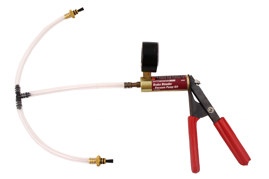
Now you are ready to perform the preliminary vacuum test.
1. Test your vacuum pump to ensure that it is not leaking. See our Testing the Test Setup Tutorial for detailed instructions.
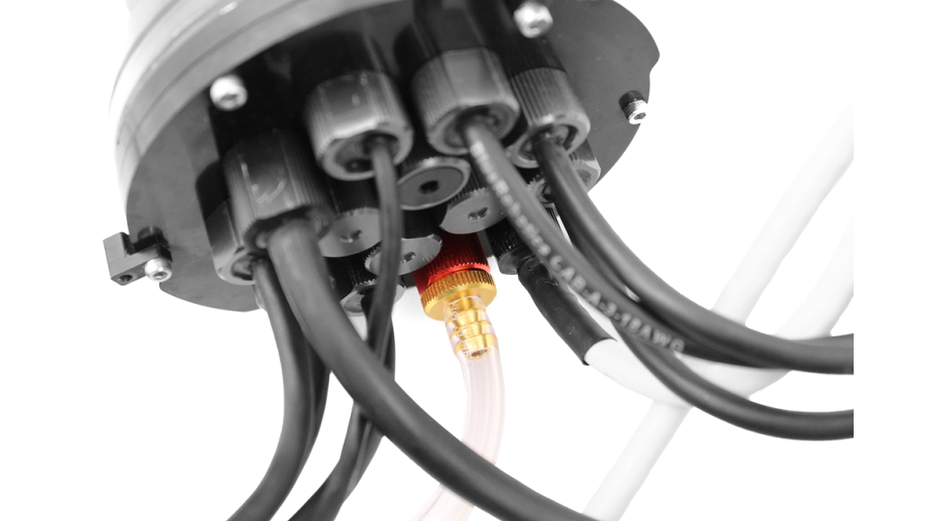
2. Insert one of the vacuum plugs into the battery enclosure vent penetrator.
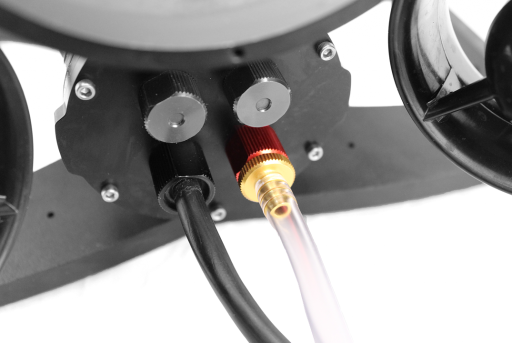
3. Insert the other vacuum plug into the electronics enclosure vent penetrator.
4. Pump the vacuum until the gauge reads 10 in. Hg [34 kPa] vacuum. If you cannot pull a vacuum, try the suggestions following step 6, below.
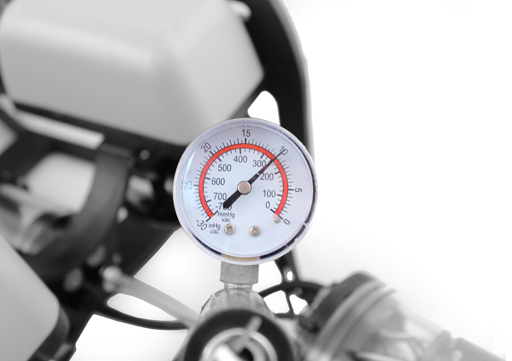
5. Let the BlueROV2 and pump sit for 15 minutes.
6. If the gauge reads above 9 in. Hg [31 kPa] after 15 minutes, your seals are acceptable.
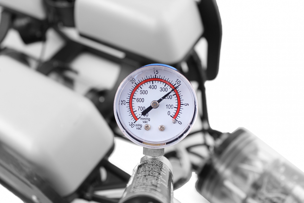
If the gauge reads below 9 in. Hg [31 kPa] vacuum after 15 minutes, you should check the following:
1. Make sure that the M3 screws on the front and back end caps of the battery and electronics enclosure are tightened using the M2.5 hex driver. If you are able to tighten one or more, attempt the vacuum test again.
2. Make sure that the penetrators on the battery and electronics enclosure are fully tightened. Check by attempting to loosen by hand. If you are able to loosen one or more, tighten them then attempt the vacuum test again.
3. Make sure that all of the O-rings are installed in the penetrators. If any are missing, install then attempt the vacuum test again.
4. Check that the face seal O-rings and radial O-rings are installed in the battery and electronics enclosures and in good condition. If you find a damaged or missing O-ring, install and attempt the vacuum test again.
If you are still having trouble holding vacuum, please contact us at [email protected]
To continue assembling the BlueROV2, remove the acrylic tube and dome from the electronics enclosure.
Cable Connections
Installing the Power Wires from the Penetrators
To install the wires from the penetrators you will need the following parts and tools:
- 1 x #2 Phillips head screw driver
1. Connect the battery power bullet connectors to bullet connectors on XT60 to bullet connector adapter.
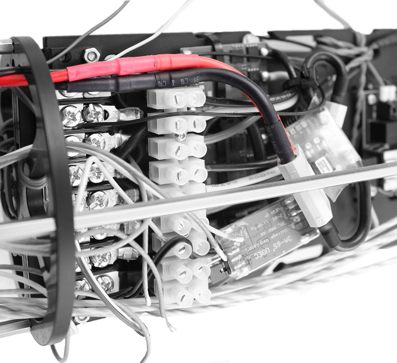
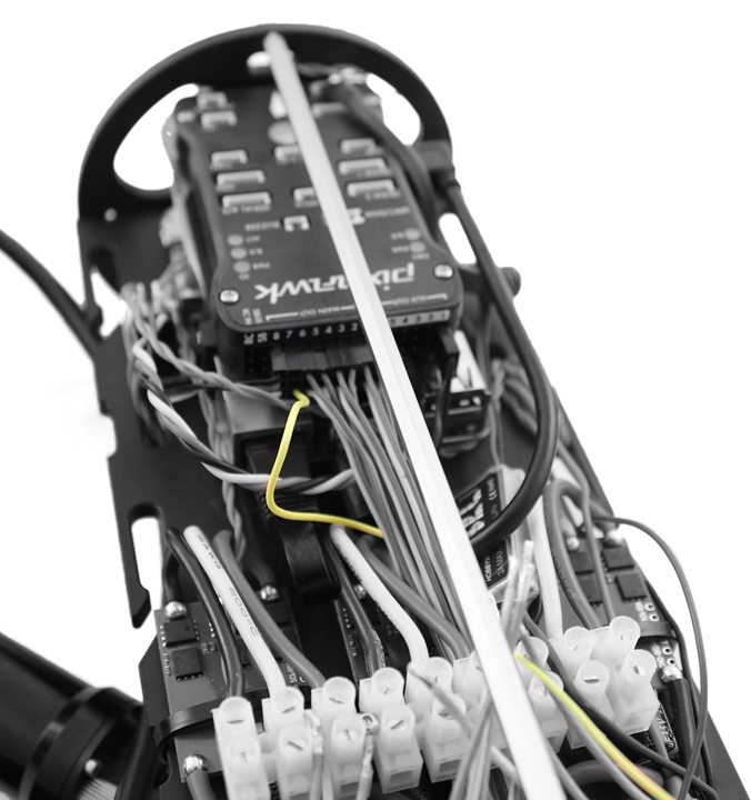
2. Connect the Lumen power wire (red) to the Power Terminal Block with the other red wires. Use the rear screw terminal that is second from the bottom. To help keep the cable routing neat, bring the cable through the ESC wires and take out most of the slack.
3. Connect the Lumen ground wire (black) to the Power Terminal Block with the other black wires. Use the rear screw terminal that is second from the bottom. To help keep the cable routing neat, bring the cable through the ESC wires and take out most of the slack.
Installing the Signal Wires from the Penetrators
To install the wires from the penetrators you will need the following parts and tools:
- 1 x Small (~2 mm) flat head screw driver
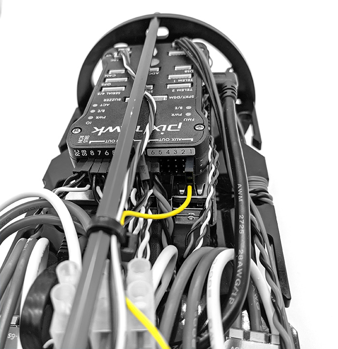
1. Connect the Lumen signal wire to the Pixhawk channel 7 with the yellow wire oriented toward the bottom of the Pixhawk.
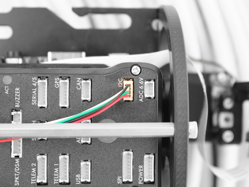
2. Connect the Bar30 cable to the I2C port on the Pixhawk.
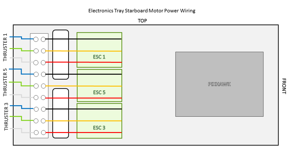
3. Connect the motor wires to the motor wire terminal block, as shown in the diagrams below.
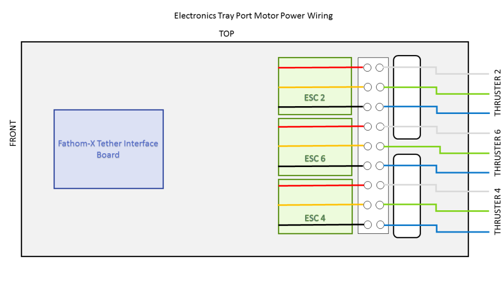
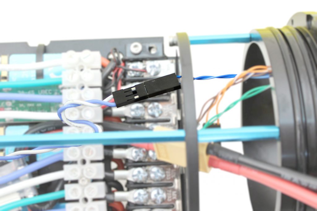
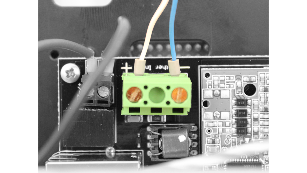
4. Connect the female tether wire connector with BLUE and WHITE wires to the extension cable that is connected to the Fathom-X Tether Interface Board. The other 6 wires do not need to be connected to anything the operate the ROV. They are for future expansion.
1. Connect the Lumen signal wire to the Pixhawk Aux Channel 1 with the yellow wire oriented toward the bottom of the Pixhawk.
2. Connect the Bar30 cable to the I2C port on the Pixhawk.
3. Unplug the camera tilt servo from Pixhawk Channel 8 and plug it into Aux Channel 2 with the yellow signal wire oriented toward the bottom of the Pixhawk.
4. Connect the motor wires to the motor wire terminal block, as shown in the diagrams below.
5. Connect the female tether wire connector with BLUE and WHITE wires to the extension cable that is connected to the Fathom-X Tether Interface Board. The other 6 wires do not need to be connected to anything the operate the ROV. They are for future expansion.
If you received your BlueROV2 prior to August 7th, 2018, the following step applies to R1 tethers:
Connect the tether wires to the Fathom-X Tether Interface Board. The other 6 wires do not need to be connected to anything the operate the ROV. They are for future expansion.
If you received your BlueROV2 prior to March 14th, 2017 you will need to install the SOS Leak Sensor.
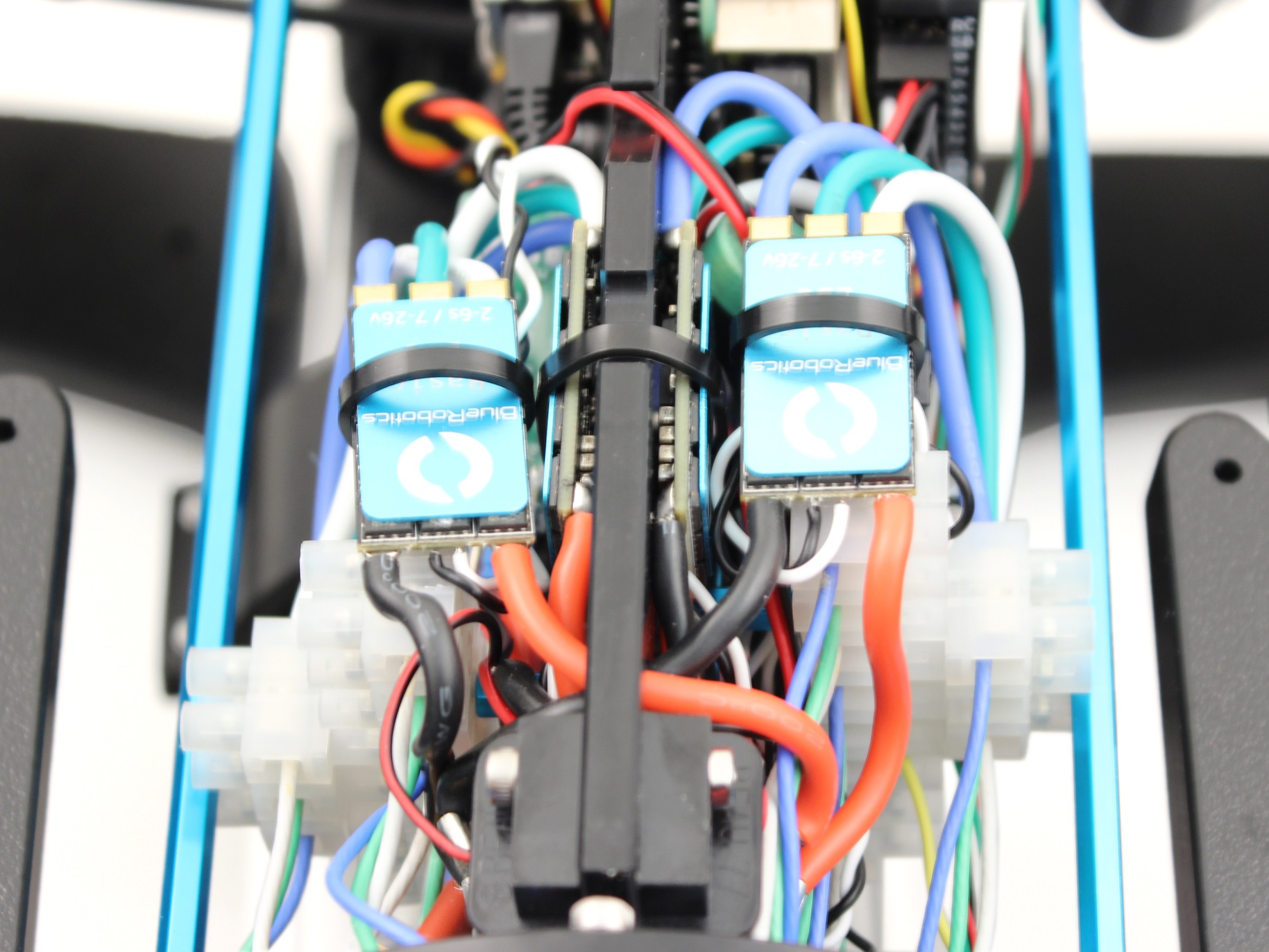
Installing Additional ESCs and Motor Wires
To install the additional ESCs from the heavy kit you will need the following parts and tools:
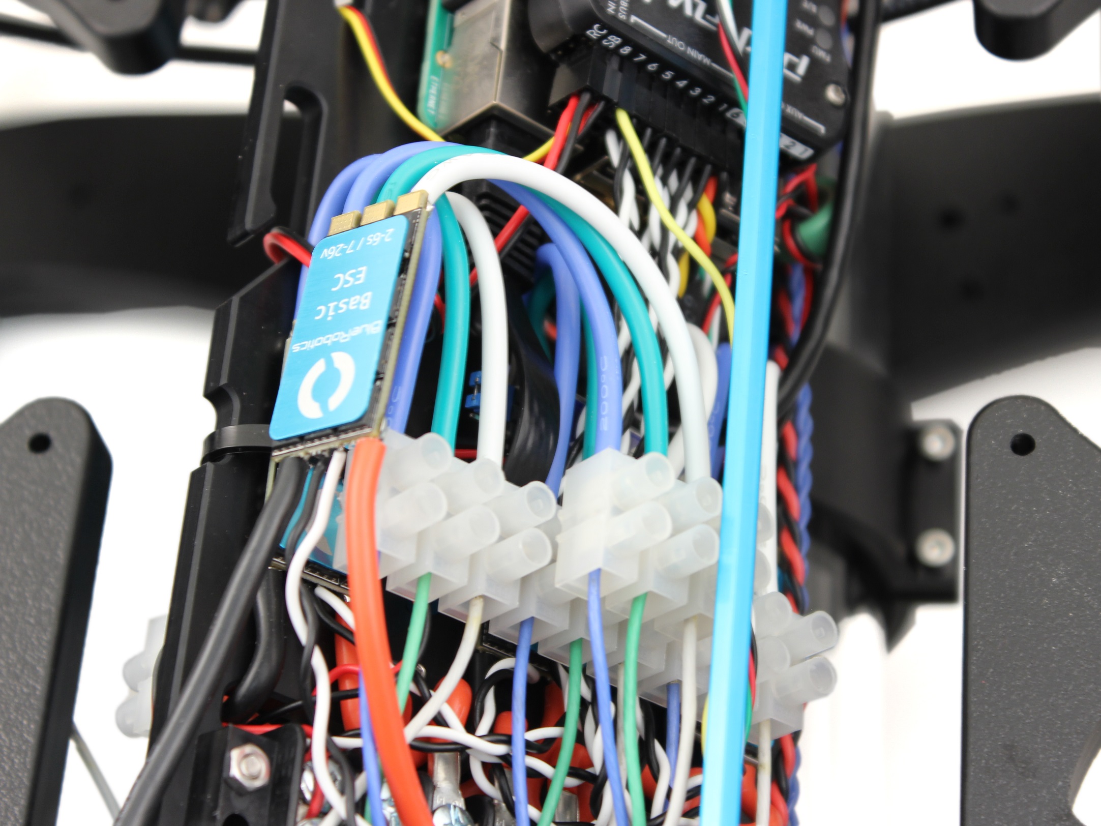
- 2 x Basic ESC (from Heavy Retrofit Kit)
- 2 x 3 Pole Euro Terminal Block (from Heavy Retrofit Kit)
- 1 x #2 Phillips head screw driver
- 1 x Small (~2 mm) flat head screw driver
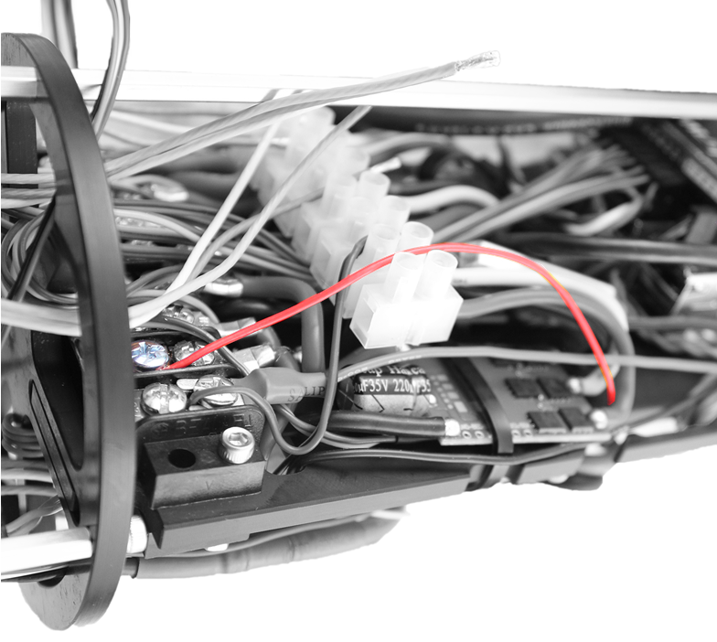
1. Slide the new 3 pole Euro terminal blocks into their mounting location on top of the 9 pole Euro terminal blocks. Position it so the aluminum standoff is between 2 of the poles. There is no connection to the existing Euro terminal blocks, they just sit on top.
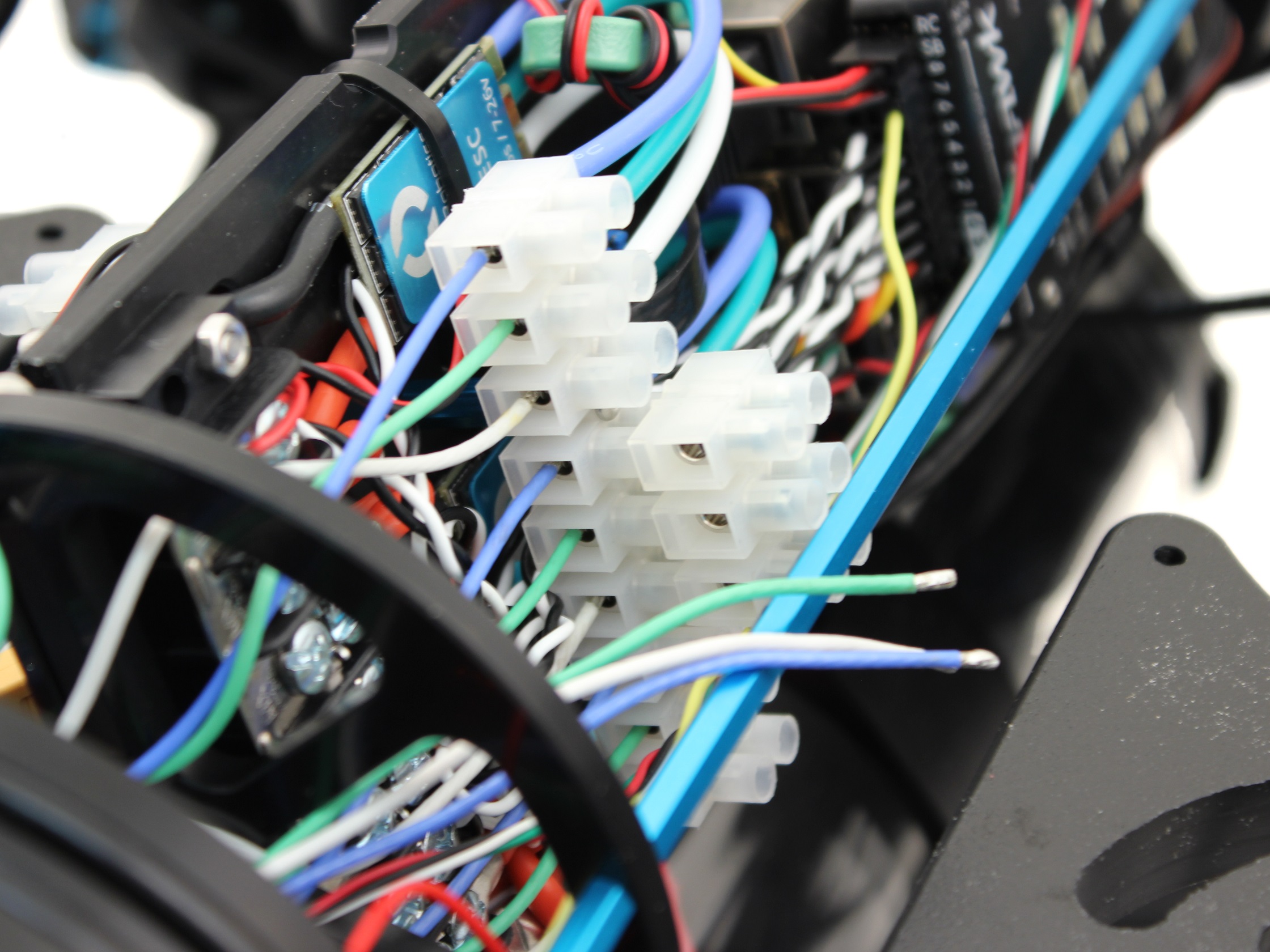
2. Connect the motor power wires from the thrusters 7 and 8 to the 3 pole Euro terminal blocks as shown, using your 2 mm flat head screw driver.
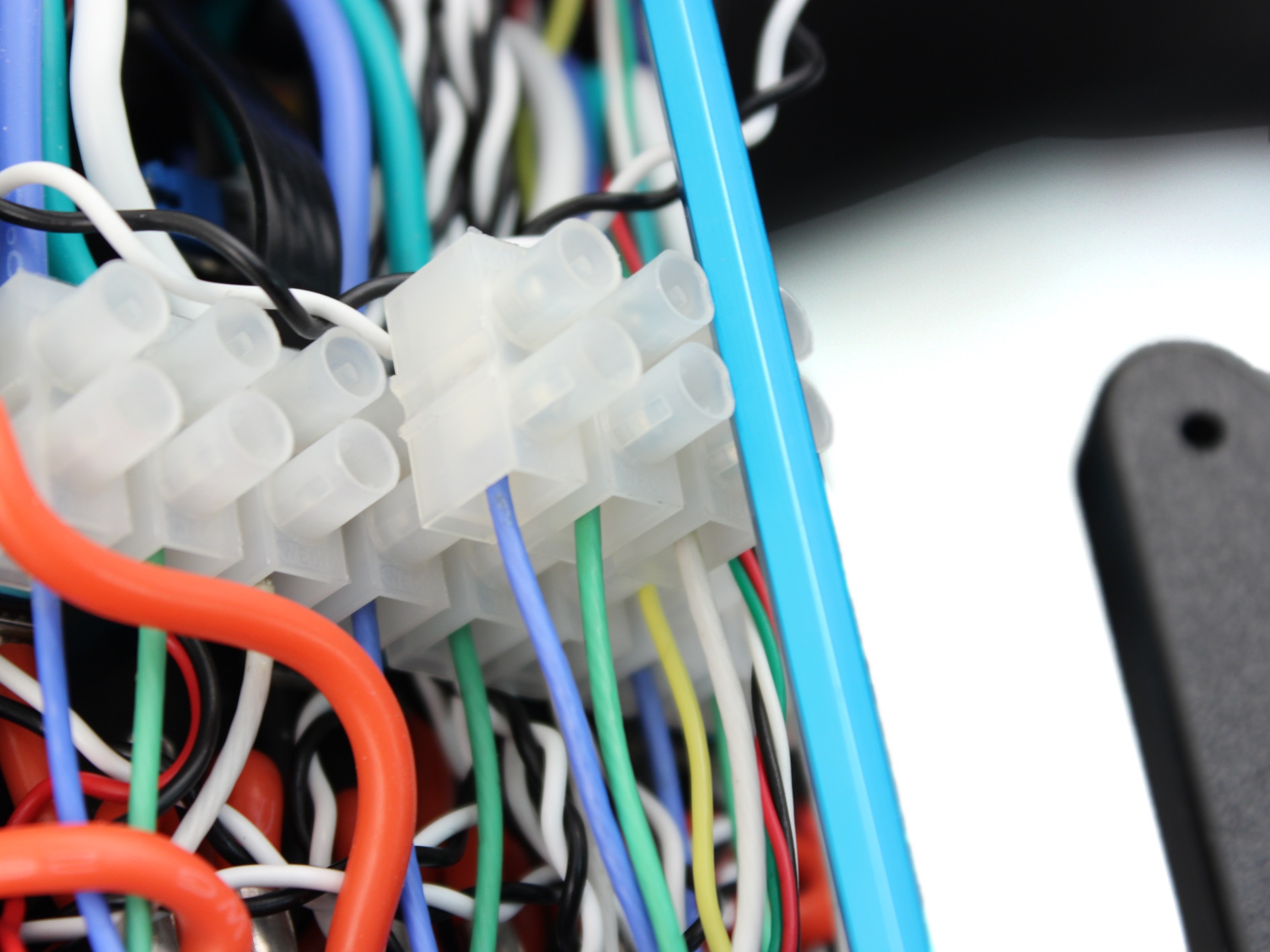
3. Connect the motor power wires from the new ESCs to the 3 pole Euro terminal blocks as shown below, using your 2 mm flat head screw driver.
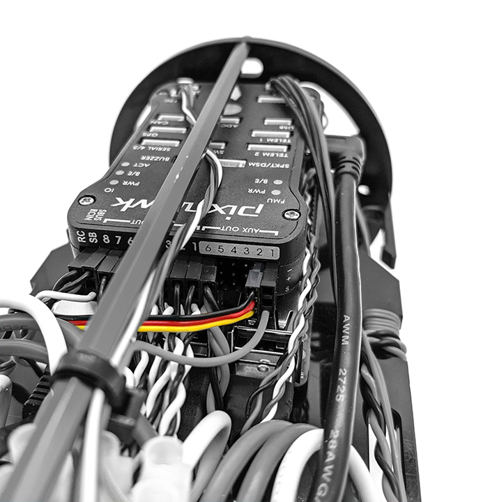
4. Plug ESC Signal Wires into Pixhawk with the following steps:
- Plug the servo signal wire for Thruster 7 into Channel 7 on the Pixhawk with the white signal wire oriented toward the bottom of the Pixhawk.
- Plug the servo signal wire for Thruster 8 into Channel 8 on the Pixhawk with the white signal wire oriented toward the bottom of the Pixhawk.
5. Connect the ESC Power Wires into open screw terminals on the respective positive and negative terminal blocks.
6. Secure the ESCs to the tray using one ziptie each and lightly wrapping them around the other ESC motor power wires.
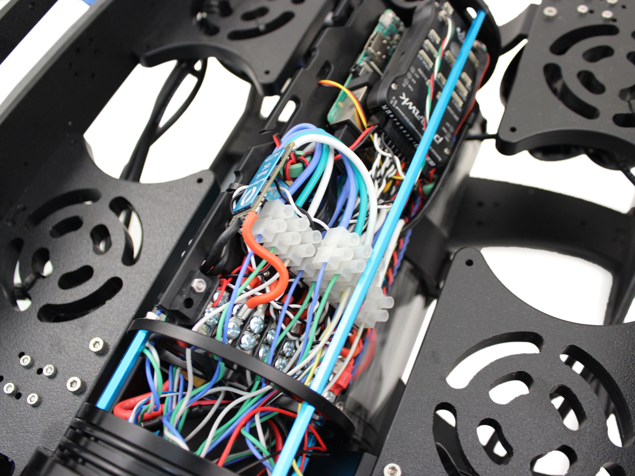
Cable Routing
To route the cables in the Electronics Enclosure so that they will not snag on the Watertight Enclosure for ROV/AUV (4″ Series) with Dome End Cap installed you will need the following parts and tools:
- 3 x 5 1/2″ zip ties
- 1 x Wire strippers or scissors
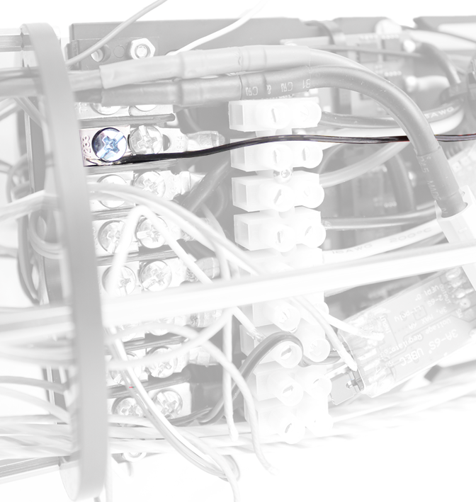
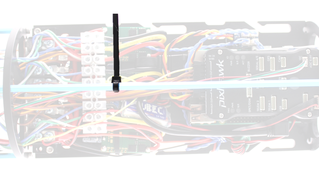
1. On the starboard side (Pixhawk side) collect the Bar30 wires and the Lumen signal wire and zip tie them to the long hex standoff slightly forward of the Motor Terminal Block using one zip tie. Make sure that the locking head of the zip tie and the wires are oriented to the inside of the long hex standoff.
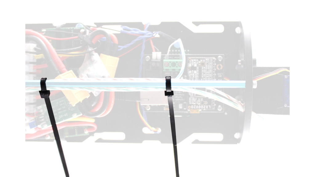
2. On the port side (Fathom-X Tether Interface Board side) collect the Fathom Tether wires and zip tie them to the long hex standoff approximately even with the back of the Fathom-X Tether Interface Board and approximately even with the Motor Terminal Block. Make sure that the locking heads of the zip ties and the wires are oriented to the inside of the long hex standoff.
Final Assembly
Mounting the Thrusters to the Frame
To mount the thrusters to the frame, you need the following parts and tools:
- 1 x 2.5 mm hex driver
- 3 x T200 Thruster with Clockwise Propeller installed
- 3 x T200 Thruster with Counter-Clockwise Propeller installed
- 1 x Bag with 16 M3x16 screws and 8 M3x12 screws in smaller bag
- 1 x Assembled ROV frame
To mount the thrusters to the frame, you need the following parts and tools:
- 1 x 2.5 mm hex driver
- 4 x T200 Thruster with Clockwise Propeller installed
- 4 x T200 Thruster with Counter-Clockwise Propeller installed
- 1 x Bag with 16 M3x16 screws and 8 M3x12 screws in smaller bag
- 1 x Bag with 8 M3x12 screws (from Heavy Retrofit Kit)
- 1 x Assembled ROV frame
The horizontal thrusters have two mounting options. One is at a 45° angle to forward, and the other is at a 30° angle to forward. The thrusters mounted at 45° will give you equal thrust in all directions. Mounting the thrusters at 30° will give you 25% more forward thrust in exchange for 25% less thrust in strafing. To mount the thrusters at 45° use the holes shown in the picture below. The hole with the asterisk is the hole that should be closest to the nose cone on the thruster.

To mount the thrusters at 30° use the holes shown in the pictures below. The hole with the asterisk is the hole that should be closest to the nose cone on the thruster.
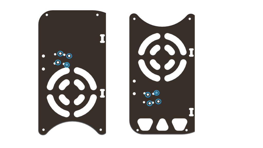
For the sake of clarity, the hole with the asterisk on the thruster shown below is the hole that is closest to the nose cone.
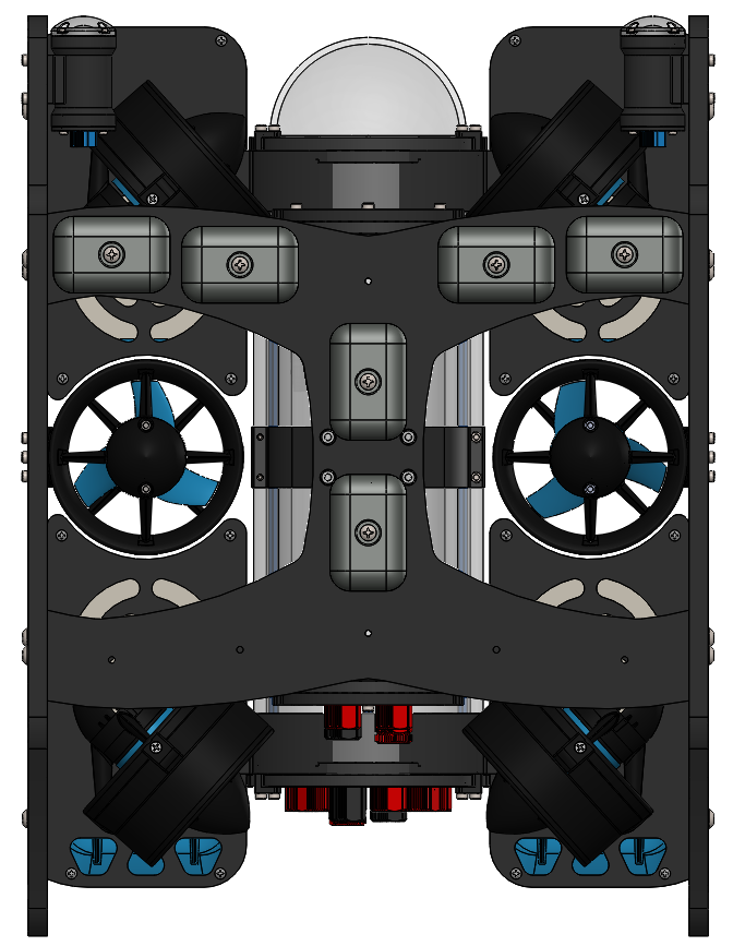
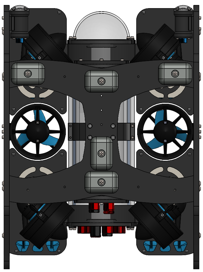
Here is a diagram of where the thrusters go, and how they should be oriented. The green thrusters should have counter-clockwise propellers and blue thrusters should have clockwise propellers. The order of installation matters here. You cannot get the front thrusters on if the rear ones were installed first.
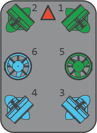
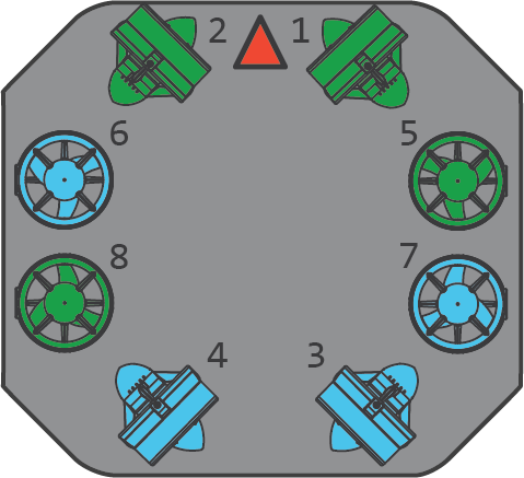
1. Install thrusters 1 and 2 underneath the front center panels, using the M3x16 screws. Tighten the screws so that they indent the frame slightly. It is physically possible to keep turning the screw at this point, but it isn’t recommended.
2. Install thrusters 5 and 6, using the M3x12 screws on the side panels. Tighten the screws so that they indent the frame slightly.
2. Install thrusters 5, 6, 7 and 8, using the M3x12 screws on the outside of the side panels. Tighten the screws so that they indent the frame slightly.
3. Install thrusters 3 and 4 underneath the rear center panels, using the M3x16 screws. Tighten the screws so that they indent the frame slightly.
Install the Thruster Guards
To install the thruster guards, you will need the following parts and tools:
- 1 Bag of 12 M4x16mm screws (from Heavy Retrofit Kit)
- 1 Bag of #4×0.5” Thread forming screws (from Heavy Retrofit Kit)
- 8 x Heavy Guard Mounting Brackets
- 2 x Heavy Guards
- 1 x Threadlocker
1. Apply one drop of threadlocker to each of the M4x16mm screws. Roll the screws around on a paper towel to evenly spread the threadlocker and to remove excess threadlocker.
2. Install 4 of the thruster guard mounting brackets on the outside of the frame using 4 M4x16 screws as shown below.
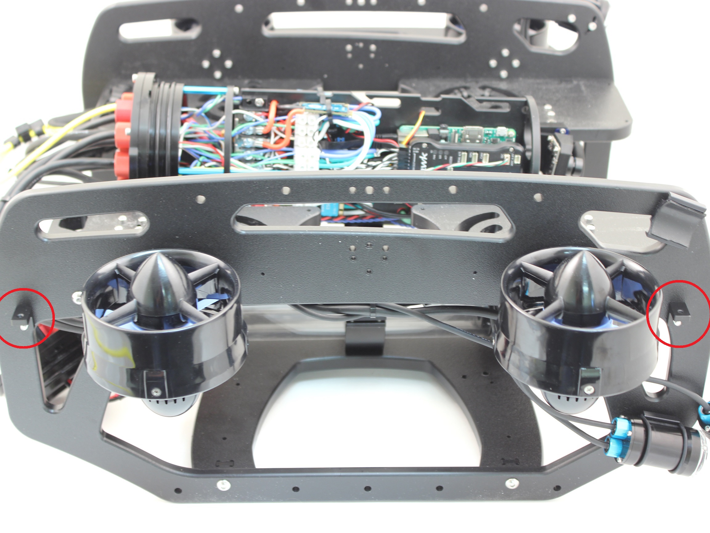
3. Place the new thruster guards on the brackets you had previously installed and make sure the holes align. The thruster guards only install in one direction with the shorter leading edge of the guard oriented towards the front end of the vehicle. If you plan to have Lumen lights mounted in the top mounts, make sure to arrange the wire so it is inside the guard, near the thruster duct. Secure the guards to the brackets using 4 M4x16 screws.
4. Install four more thruster guard mounting brackets (two on each side) in the holes near the middle of the ROV using one M4x16 screw and one #4×0.5” thread forming screw per bracket.
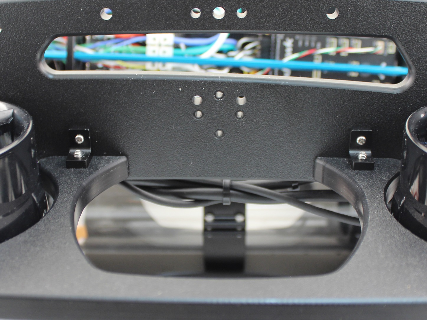
5. Tighten all the screws evenly until they are tight enough to properly secure the thruster guard to the frame and there is no excess freedom of movement.
Mounting the Lights
To install the Lumen mounts you will need the following parts and tools:
- 1 x Bag with four M3x12 socket head cap screws
- 1 x 2.5 mm hex driver
- 1 x BlueROV2 frame
- 1 x Threadlocker
1. Apply one drop of threadlocker to each of the M3x12 screws. Roll the screws around on a paper towel to evenly spread the threadlocker and to remove excess threadlocker.
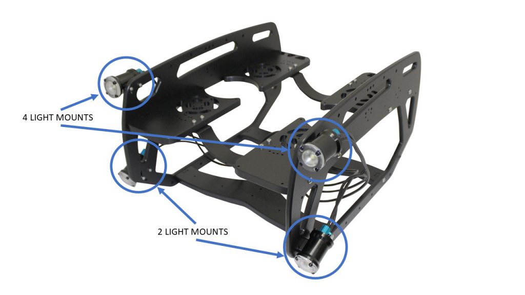
2. Install the Lumens in the locations specified depending on how many light pairs you have. Installing the lights outside the frame reduces the amount of backscatter the camera sees. Make sure not to overtighten the screw that goes into the slot. Only tighten it so that it slightly indents the frame.
Adding Desiccant to the Electronics Enclosure
If you ordered your BlueROV2 prior to February 14, 2018 you will need to order Moisture Indicating Silica Gel Desiccant in order to complete this step. This step is optional, but it will improve the usability of the BlueROV2, especially if you are planning on operating your ROV in humid environments with cold water.
The desiccant will absorb humidity that is inside of the Electronics Enclosure to prevent the dome from fogging up during dives. It will turn pink as it absorbs humidity.
1. Install the desiccant bag near the Fathom-X Tether Interface. This step will have to be combined with installing the Watertight Enclosure (4″ Series) over the Electronics Tray since the bag will be “floating” inside of the enclosure.

Mounting the Electronics Enclosure onto the Frame
To mount the Electronics Enclosure to the frame you need the following parts and tools:
- 1 x Watertight Enclosure for ROV/AUV (4″ Series) with Dome End Cap installed
- 1 x Bag with four M3x16 screws
- 1 x 2.5 mm hex driver
1. Apply silicone grease to the two radial O-rings on the O-Ring Flange (4″ Series) that is attached to the Electronics Tray then install the Watertight Enclosure (4″ Series) with installed Dome End Cap to the O-Ring Flange (4″ Series).
2. Mount the Electronics Enclosure to the frame using the M3x16 screws so that the dome is on the same side as the front center panels (the center panels BlueROV2 the 3 large holes). Install the M3x16 screws through the extensions and into the Enclosure Cradle (4″ Series). It is easier to install these screws if the extensions are not fully tightened until all screws are through the extensions and threading into the Enclosure Cradle (4″ Series). This allows to extension to rotate so you can find the threaded hole in the Enclosure Cradle (4″ Series) easily.
Mounting the Tether to the Frame
The tether needs to be firmly mounted to the frame to prevent the tether penetrator from being loosened through normal use. To do this, you will need the following parts and tools:
- 1 x Bag with thimble and 5 large zip ties
- 1 x Fathom Tether
- 1 BlueROV2 frame
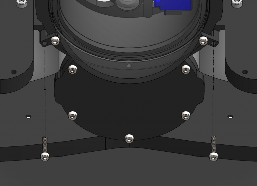
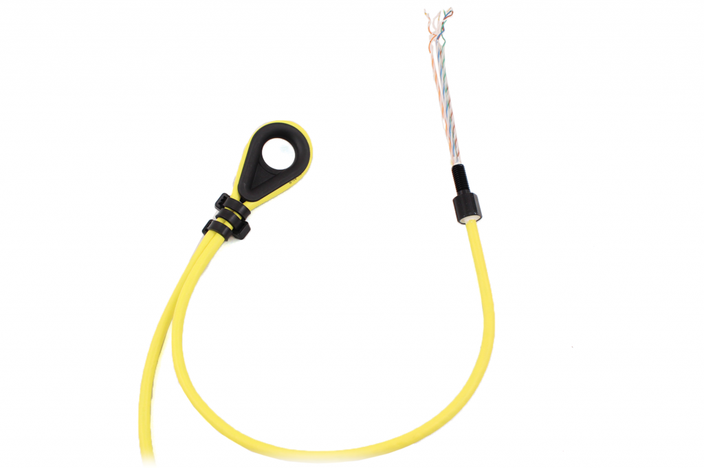
1. Loop the tether around the plastic thimble at a point about 12 inches (30 cm) away from the tether penetrator.
2. Firmly attach 3 of the zip ties, alternating directions as they are installed, around the tether right where it enters and exits the thimble. Hold the tether firmly in place against the thimble until it is secured.
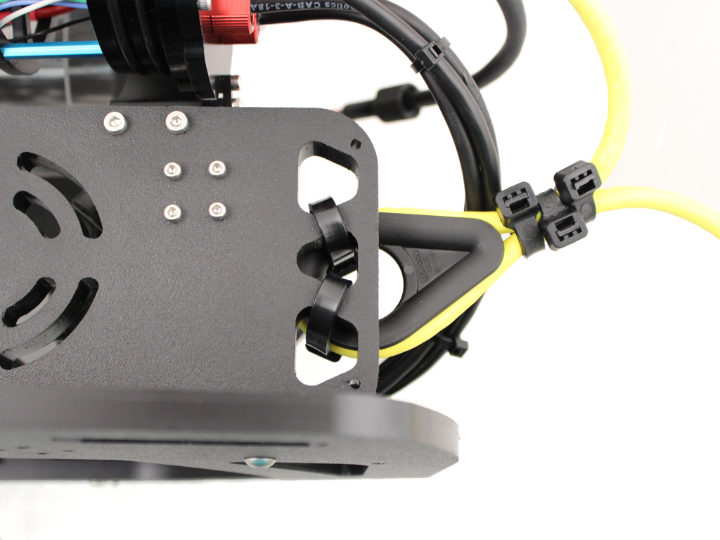
3. Attach the thimble to the rear panel as shown.
Thruster and Lumen Cable Management
To clean up the thruster and lumen wires, you will need the bag of 30 zip ties and your scissors/wire cutters.
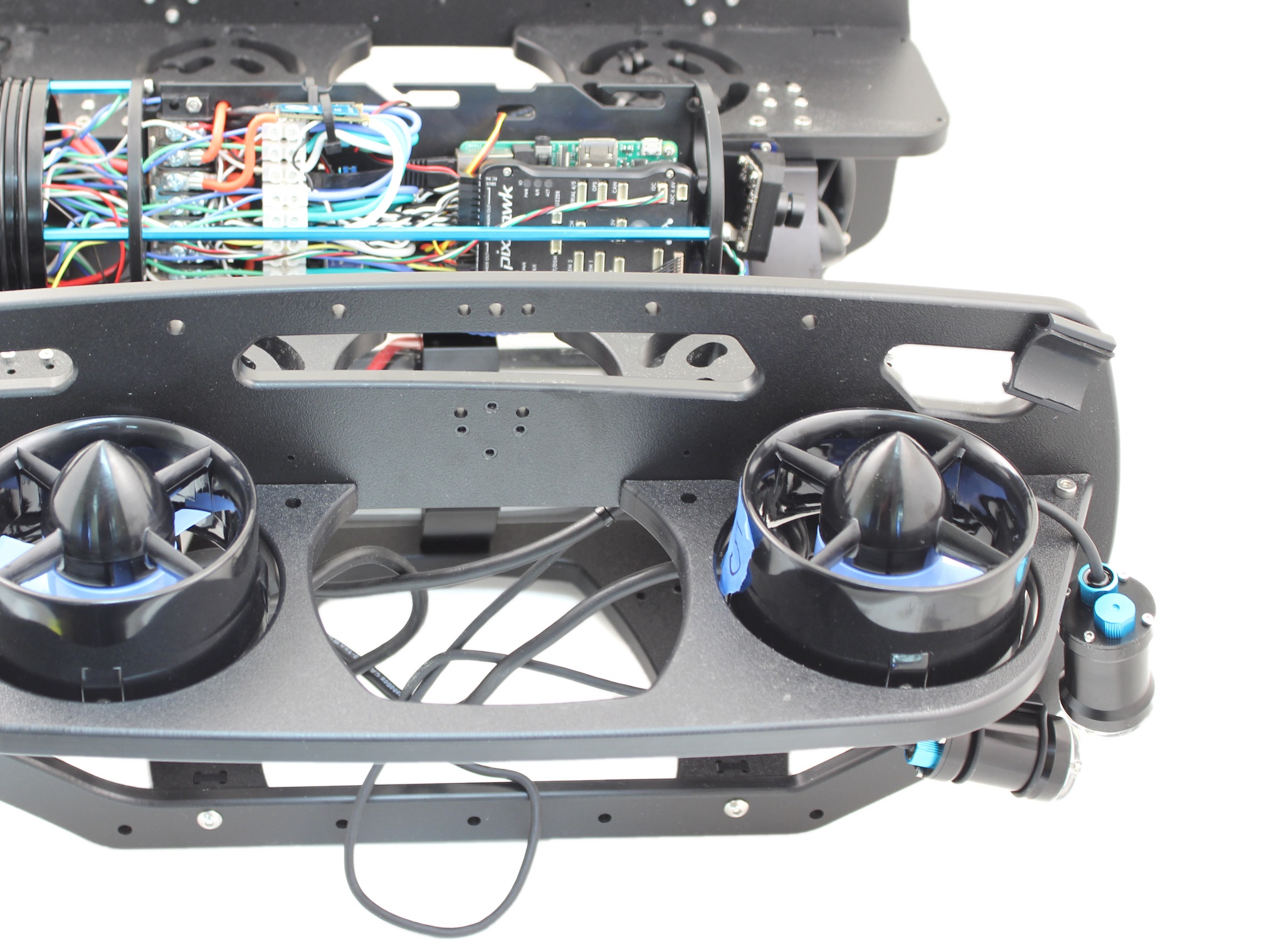
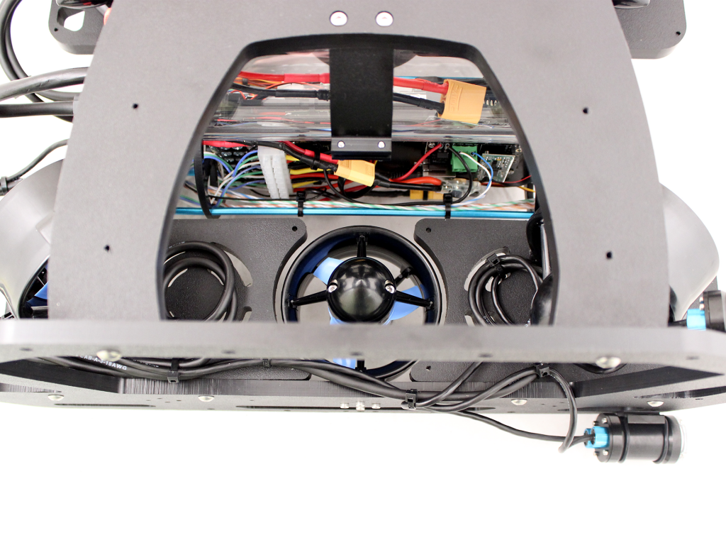
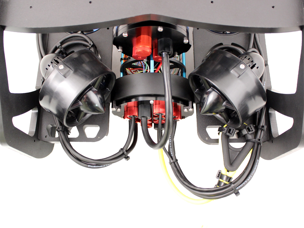
The primary goal of Thruster and Lumen cable management is to prevent the wires from getting cut by the propellers. Make sure to check that no wire can reach a propeller after you have finished routing the cables. Below are some examples of what the cable routing should look like.
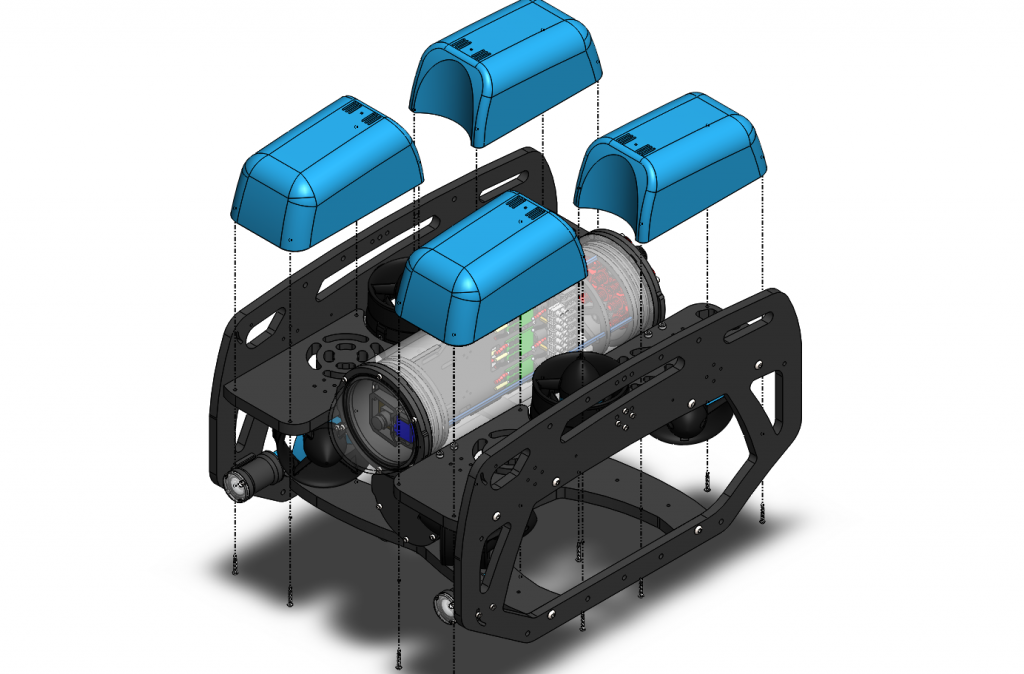
Installing the Fairings and Buoyancy
The buoyancy comes pre-installed in the fairings, but make sure it is still in all of the fairings prior to installing the fairings. To install the fairings, you will need the following parts and tools:
- 4 x Fairings with buoyancy installed
- 1 x Bag with 16 self tapping screws
- 1 x #2 Phillips head screwdriver
- 4 x Fairings with buoyancy installed
- 2 x Heavy additional buoyancy blocks
- 2 x Heavy fairings
- 1 x Bag with 16 self tapping screws
- 1 x Bag of 4 flat head fairing screws (from Heavy Retrofit Kit)
- 1 x #2 Phillips head screwdriver
1. Install the self tapping screws through the center panels and into the fairings.
2. Place the round Heavy buoyancy blocks into the open space between the fairings. Ensure the flat sides of the blocks are parallel to the sides of the ROV.
3. Place the new plastic Heavy fairings on top of the buoyancy blocks and secure them to the previous fairing blocks using the included flat head fairing screws.
Mounting Ballast to the Frame
To mount the ballast to the frame you need the following parts and tools:
- 7 x 200g ballast weights
- 7 x 8-16 Thread, 5/8″ Long, Thread-Forming Screw
- 1 x #2 Phillips head screwdriver
- 7 x 200g ballast weights
- 3 x 200g additional ballast weights (from Heavy Retrofit Kit)
- 10 x 8-16 Thread, 5/8″ Long, Thread-Forming Screw
- 1 x #2 Phillips head screwdriver
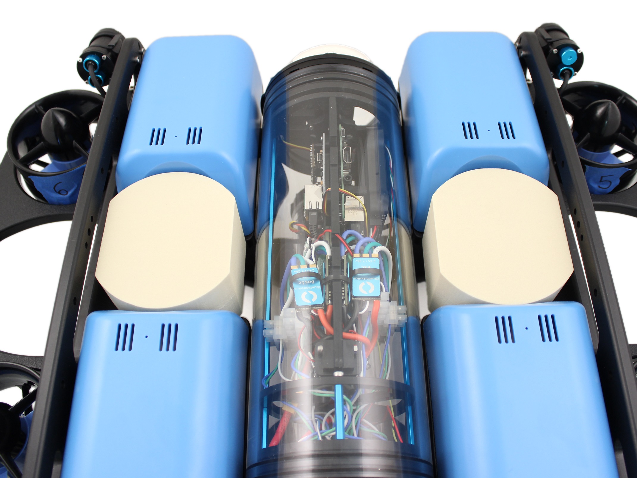
To get the longest battery life and the best driving experience, it is important to have the ROV close to balanced from front to back in water and close to neutrally buoyant. Trimming the ballast may involve a bit of trial and error. The pictures below should provide a good starting point for mounting ballast if you have a stock BlueROV2 with one of the recommended batteries.
BlueROV2 with 2 Lumen Lights
BlueROV2 with 4 Lumen Lights
Topside Setup
If you ordered your BlueROV2 on or after August 7th, 2018, your kit will include a Fathom-X Tether Interface (FXTI). Please refer to the FXTI documentation for connection instructions.
Fathom-X Tether Interface (FXTI) Usage Guide
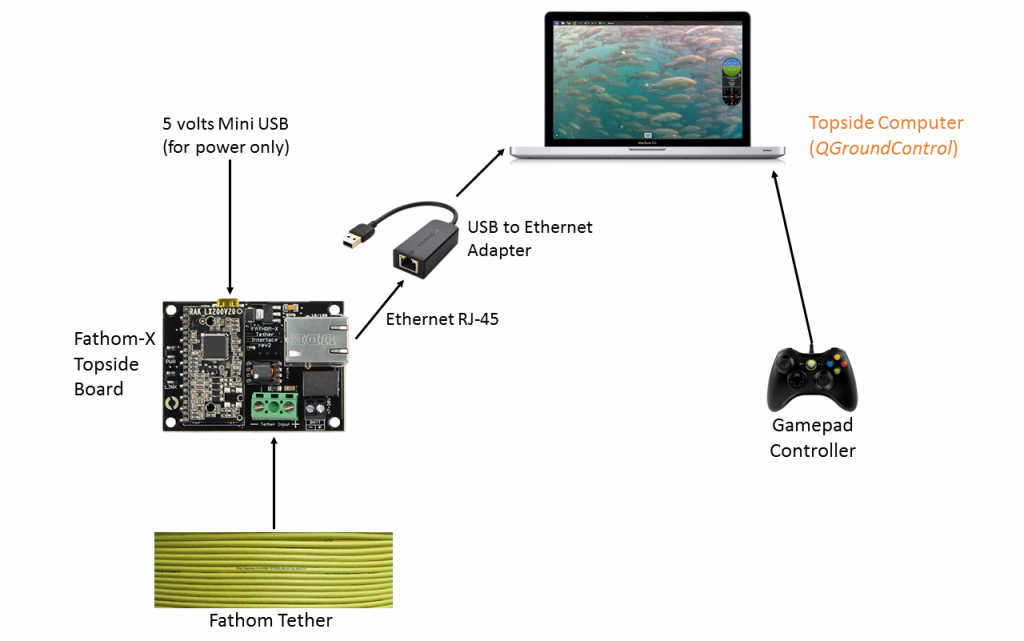
If you ordered your BlueROV2 prior to August 7th, 2018, you will need the following parts and tools:
- 1 x Fathom-X Tether Interface Board
- 1 x 2 mm flat head screw driver
- 1 x Computer (Mac, Windows, Linux)
- 1 x Ethernet cable
- 1 x USB to Ethernet adapter (if your computer does not have an Ethernet Port)
- 1 x Mini-USB cable
1. Connect the Fathom Tether to the Fathom-X Tether Interface Board.
2. Connect the Ethernet port of the Fathom-X Tether Interface Board to you computer. If you do not have an Ethernet port on you computer connect the Ethernet port on the Fathom-X Tether Interface Board to a USB to Ethernet adapter then connect the adapter to your computer.
3. Connect your Mini-USB the the Fathom-X Tether Interface Board and to a USB power supply that can supply at least 500 milliamps. Most computer USB ports can do this, but if the “Link” LED does not light up try using a USB charger.
Next Steps
First, set up the software on your topside computer. Please see our Software Setup page.
BlueROV2 Software Setup (R3 and Older)
Issue Reporting
We’re always trying to make our documentation, instructions, software, and user experience better. If you’re having an issue with anything, please report it so that we can address it as soon as possible! Here’s where to do that depending on what’s wrong:
- ArduSub Issues: For anything related to the ArduSub software that runs on the Pixhawk and controls the ROV, reports issues on the ArduSub Github Issues Page. If you’re unsure where your issue should be posted, you can report it here.
- QGroundControl Issues: For anything related to the QGroundControl software, joystick setup, video streaming, etc., please report an issue on the QGroundControl Github Issues Page.
- Documentation: For anything related to the documentation and instructions here, please report an issue by submitting an e-mail to [email protected].