
Outland Technology Power Supply BlueROV2 Integration
Introduction
The Outland Technology Power Supply allows the BlueROV2 to be powered through the tether so that you can run indefinitely and without any batteries! It has a safety-focused design that is simple to install, easy to use, and built with the rugged reliability that Outland Technology is known for. Installation is easy and straight-forward by removing the battery enclosure, installing the OTPS enclosure, and installing a new tether carabiner.


Version Compatibility
The current version of the OTPS kit (purchased January 2022 or later) is directly compatible with BlueROV2 version R3 or later. These versions have dual power cables with compatible 5.5 mm bullet connectors.
If you are integrating the current OTPS kit version (purchased January 2022 or later) on an older R1 or R2 version of the BlueROV2, you will need to upgrade the Power Sense Module in your BlueROV2 to the current version (R3 or later) with 5.5 mm bullet connectors. An additional available penetrator hole in the Electronics Enclosure end cap is also required to accommodate the dual power cables.
Parts and Tools
Apart from the OTPS kit and the BlueROV2, you will need the following to complete the installation:
You will also need:
- 1 x #1 Phillips head screwdriver (BlueROV2 kit)
- 1 x Bottle of Threadlocker (not included)
Removing the Battery Enclosure
To remove the battery enclosure from your BlueROV2 and install the Outland Technology Power Supply (OTPS) ROV Enclosure, you will need the following tools:
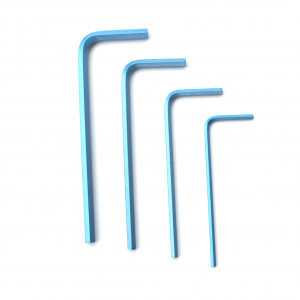
- 1 x 2.5 mm hex driver
- 1 x 3 mm hex key or driver
1. To ensure your ROV is completely powered off, please remove the battery completely from the 3” enclosure and place to the side.
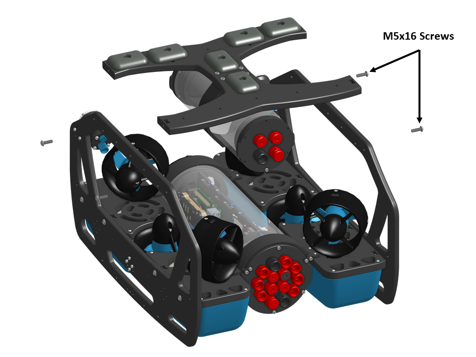
2. Remove the bottom panel from the BlueROV2 frame with a 3 mm hex key or driver.
3. Remove the M3x12 screws holding the two sections of the 3″ clamp together with a 2.5mm hex driver.
4. Remove the 3″ Battery Enclosure from the clamps.
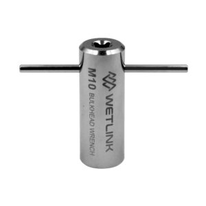
5. Open the Battery Enclosure and remove the two battery cable penetrators from the end cap by loosening the penetrator nuts at the back of the end cap with the bulkhead wrench that came in the BlueROV2 kit. If you have a BlueROV2 with a single power cable, you may skip this step. The Battery Enclosure will no longer be used for this installation.
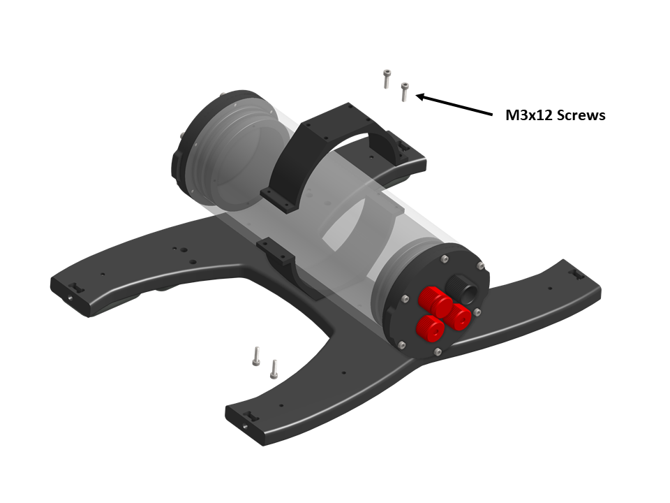
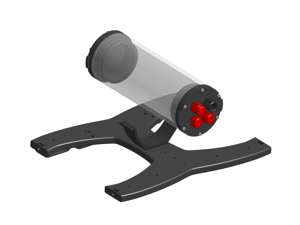
6. Place the OTPS ROV Enclosure between the two Enclosure Clamps (3″ Series). Orient the OTPS ROV Enclosure so the power cables are at the top.
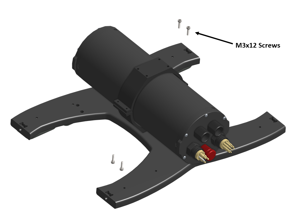
7. The Enclosure Clamps have tapped holes on one side and untapped holes on the other. Install the four M3x12 screws into the Enclosure Clamps (3″ Series) so that the screws pass through the untapped holes on the first clamp and are secured into the tapped holes on the alternate clamp. Install all four screws loosely at first and then slowly tighten them on both sides evenly. Take care not to over tighten the screws. Keep the OTPS ROV Enclosure approximately centered in the Enclosure Clamps (3″ Series).
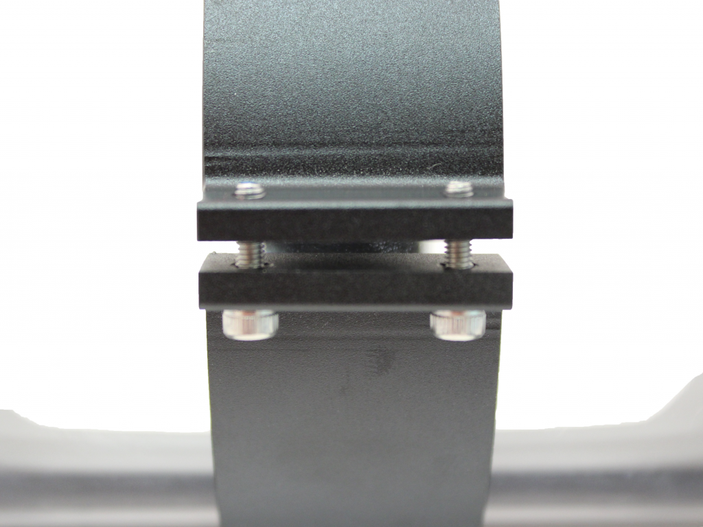
8. When you are finished tightening the screws, both sides should look similar to this.
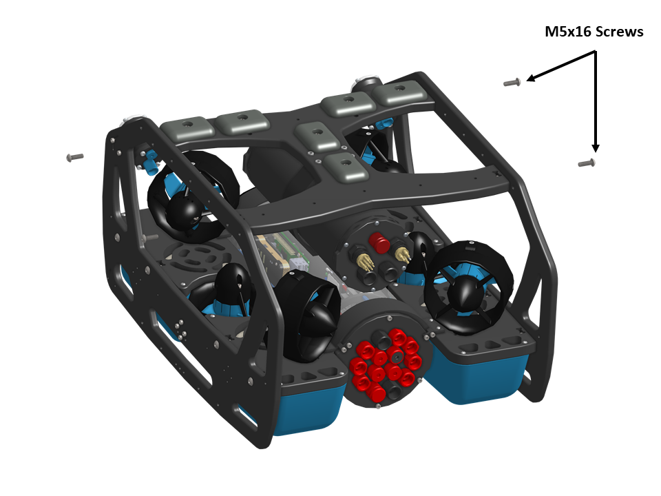
9. Using the four M5x16 screws that were previously removed, re-install the bottom panel onto the BlueROV2 frame. Tighten these screws using the provided 3 mm hex key.
Removing the Tether and Battery Cable Penetrators
To remove the tether and battery cable penetrators from your BlueROV2, you will need the following tools:
- 1 x 2.5 mm hex driver
- 1 x Penetrator wrench
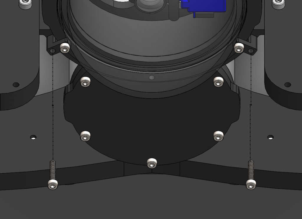
1. Remove the 4” electronics enclosure from the ROV by removing the M3x16 screws that mount the enclosure to the ROV cradle.
2. Remove the Vent Plug from the Vent Penetrator Bolt on the electronics enclosure. Remove the 4″ tube and forward dome assembly from the rear end cap.
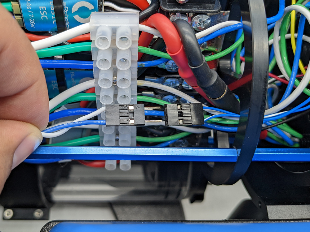
3. Disconnect the blue and white tether data connection wires.
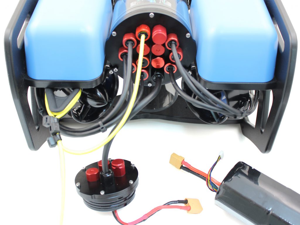
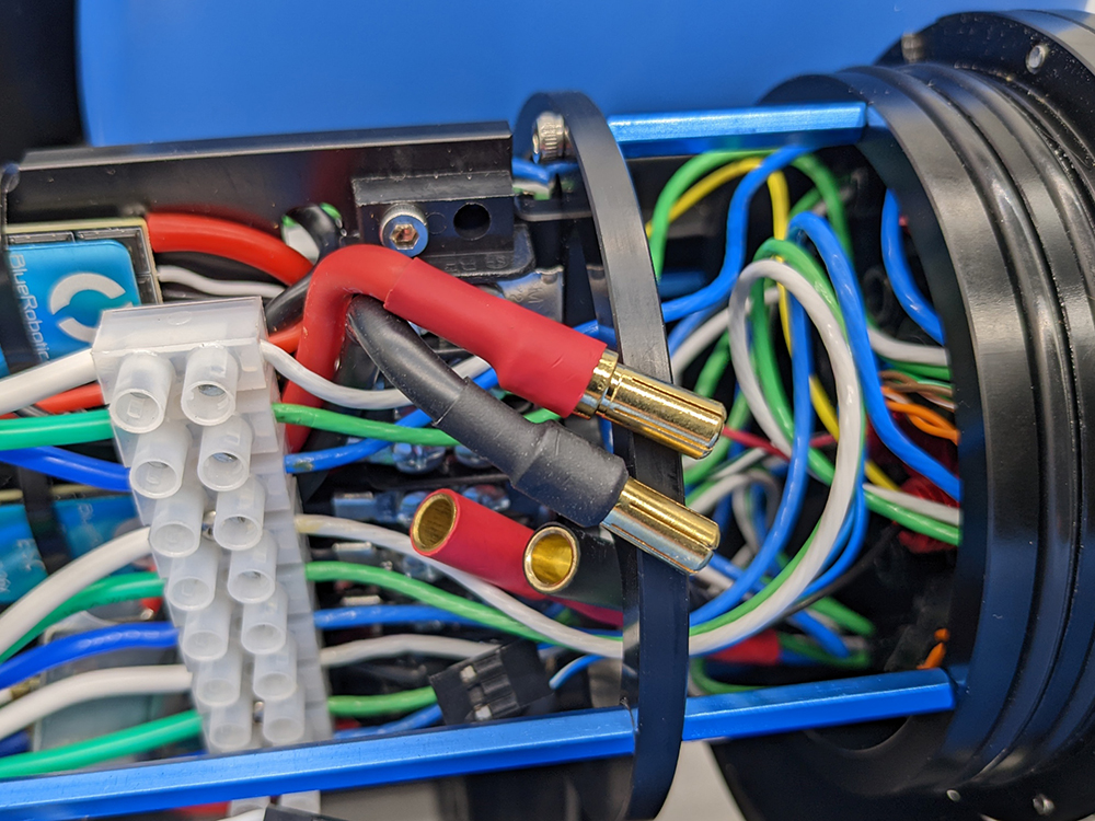
4. Disconnect the bullet connector power wires from the battery cables and the power sense module.
5. Remove the penetrators as shown in the pictures below using the bulkhead wrench. The penetrators that need to be removed depend on whether you have an 18-hole or 14-hole end cap. Be sure to keep the o-rings that were installed under the blank penetrators. Set these to the side as they will be used later.
18-Hole End Cap
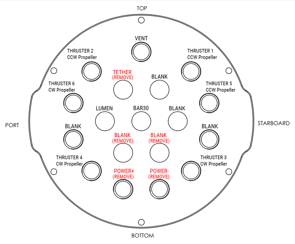
Remove these penetrators
14-Hole End Cap
Because the OTPS Enclosure uses dual power cables instead of a single battery cable, you will need to decide which penetrator hole to use for the additional power cable based on your setup. For a stock 14-hole end cap, the configuration below is recommended.
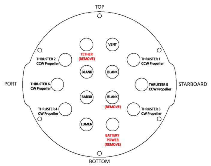
Remove these penetrators
Install the OTPS Data and Power Penetrators
To install OTPS data and power penetrators into the end cap, you will need the following parts and tools:
- 3 x Penetrator Nut (from OTPS kit)
- 3 x Penetrator O-ring (from OTPS kit)
- 1 x Silicone Grease – 10g Tube
- 1 x Isopropyl Alcohol Wipe
- 1 x Penetrator wrench
1. Wipe the exterior surface of the electronics enclosure endcap clean with isopropyl alcohol or isopropyl alcohol wipes, and make sure it is free of any particles in the areas where the penetrator O-ring will sit.
2. Remove the O-rings and penetrator nuts from the OTPS Enclosure data and power cables. Apply silicone grease to the o-rings.
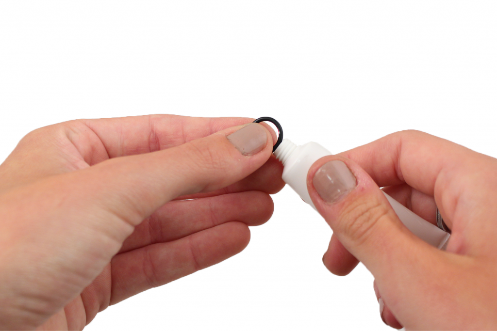
3. Install the O-rings onto the OTPS data and power cable penetrators.
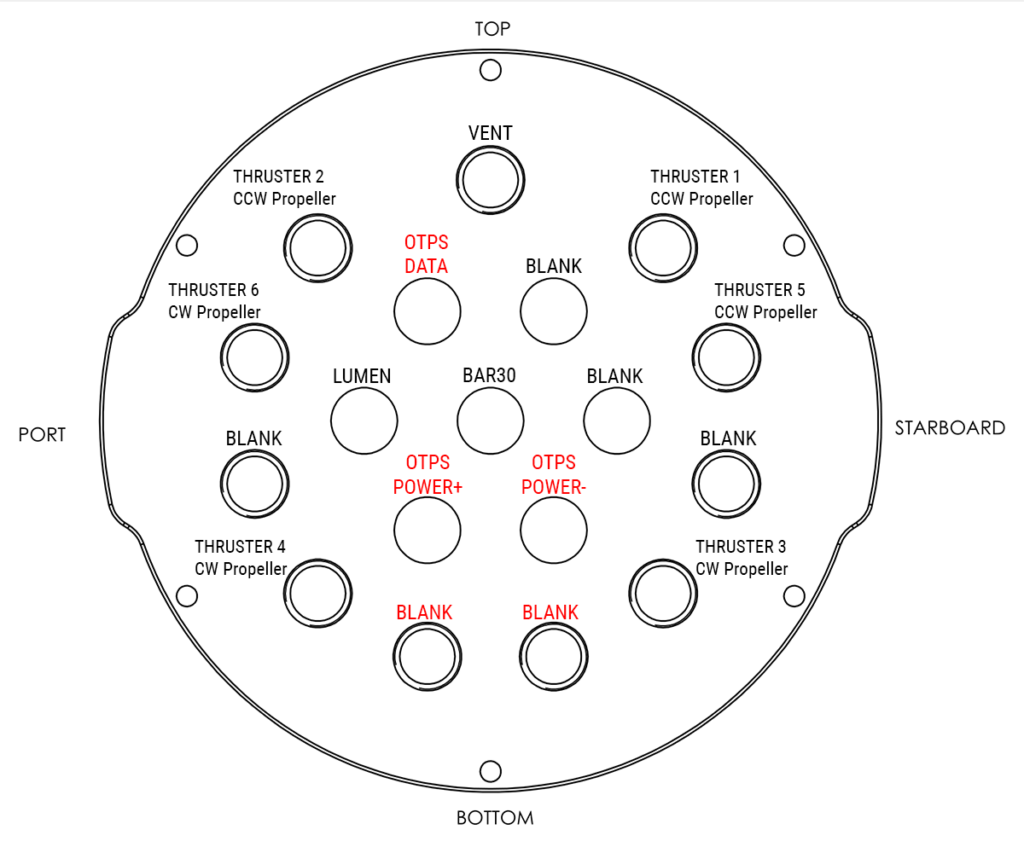
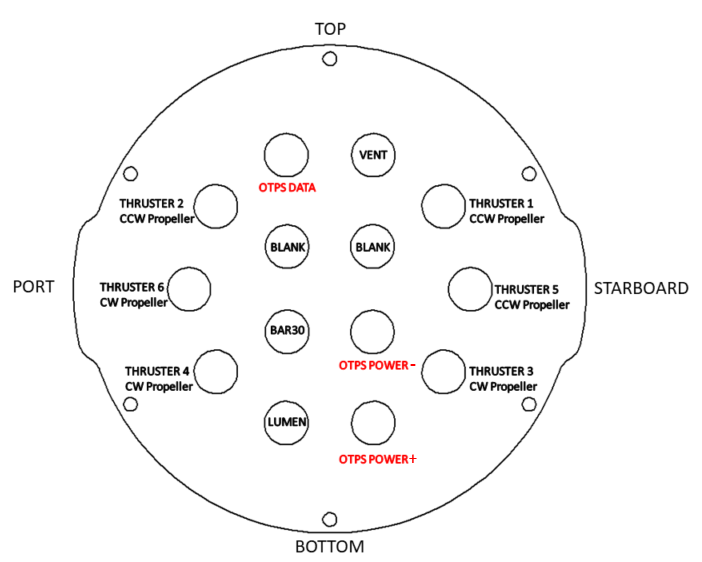
4. Install the OTPS data, OTPS power+ (red shrink wrap), and OTPS power- (black shrink wrap) cable penetrators into the end cap. The recommended configuration for the 18-hole or 14-hole end caps are shown below.
18-Hole End Cap
The OTPS power cables need to be installed in the non-threaded penetrator holes the blank penetrators were removed from previously. Install the blank penetrators you set aside into the end cap as shown below.
14-Hole End Cap
Tighten the penetrator nuts to finger tight, then use the bulkhead wrench to tighten it an additional ~1/16 of a turn. If you can’t loosen the penetrator with your fingers, it is tight enough.
Wiring Connections
1. Connect the bullet connector power wires from the OTPS power cables and the power sense module, matching the colors of the cables (red to red and black to black).
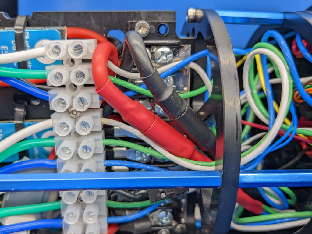
2. Connect the female OTPS Data wire connector with BLUE and WHITE wires to the extension cable that is connected to the Fathom-X Tether Interface Board. The other 6 wires do not need to be connected to anything to operate the ROV. They are for future expansion.
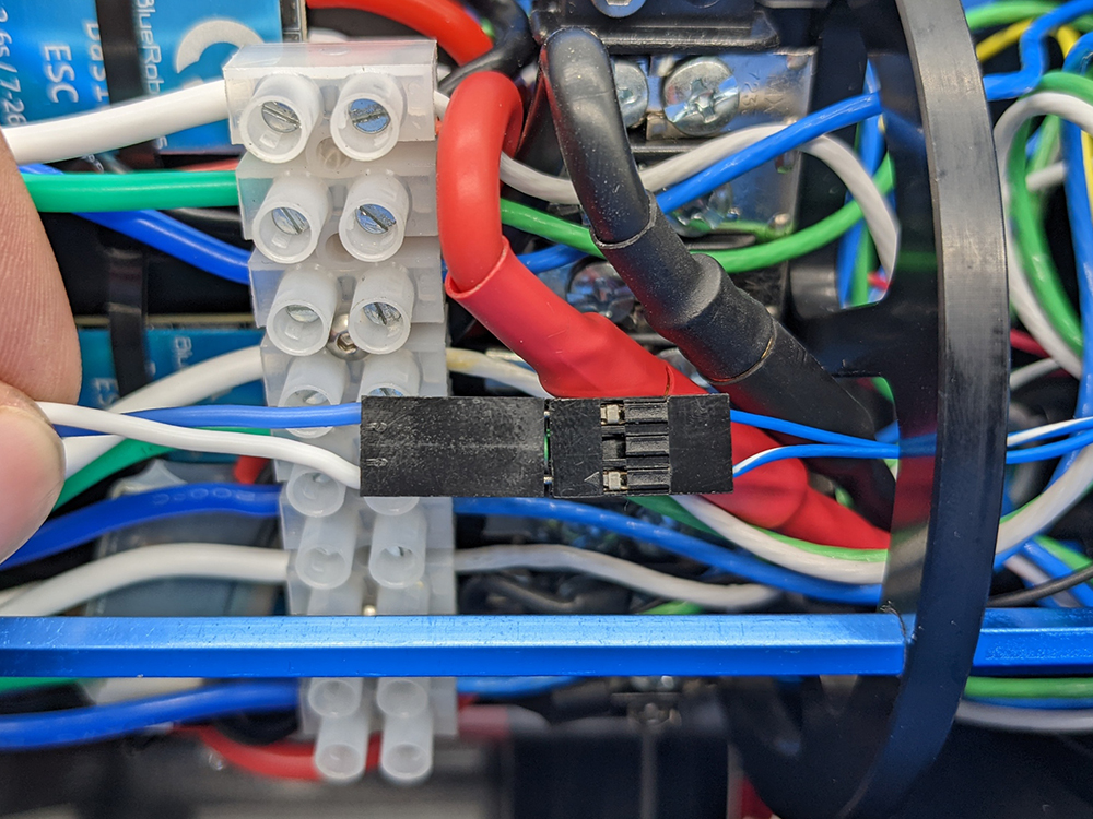
3. Outland Technologies has determined that the high voltage step-down power supply can add additional electrical noise to the system, which can result in problems communicating with the Bar30 Pressure sensor over I2C. A ferrite core is included, and is intended to suppress this interference. To install, disconnect the pressure sensor, pass the cable through the center of the core, and secure it close to the connector. Reconnect the Bar30, and if issues are encountered, consider adding a second ferrite core positioned at the sensor end of the cable.
Reassemble BlueROV2 Electronics Enclosure
To reassemble your BlueROV2 Electronics Enclosure, you will need the following parts and tools:
- 4 x M3x16 screws that were placed off to the side during disassembly
- 1 x Silicone Grease – 10g Tube
- 1 x 2.5 mm hex driver
Reinstall 4” Watertight Enclosure onto ROV with the following steps:
1. Apply silicone grease to the two radial O-rings on the O-Ring Flange (4” Series) that is attached to the Electronics Tray then install the Watertight Enclosure (4” Series) with installed Dome End Cap to the O-Ring Flange (4” Series).
2. Mount the Electronics Enclosure to the frame using the M3x16 screws so that the dome is on the same side as the front center panels (the center panels without the 3 large holes). Install the M3x16 screws through the clips and into the Enclosure Cradle (4” Series). It is easier to install these screws if the clips are not fully tightened until all screws are through the clips and threading into the Enclosure Cradle (4” Series). This allows to clips to rotate so you can find the threaded hole in the Enclosure Cradle (4” Series) easily.
Install Tether Carabiner
To remove the old tether and install the new tether carabiner, you will need the following parts and tools:
- 1 x #1 Phillips head screwdriver
- 1 x Wire cutters or scissors (for cutting zip ties)
- 1 x 316 Stainless Steel Carabiner (200 lb capacity)
- 2 x 8.5″ Zip ties
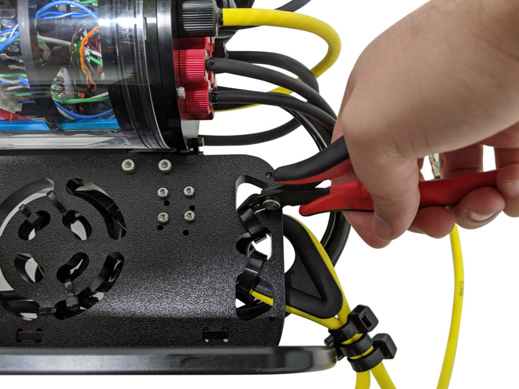
1. Remove the rear fairing covering the old tether thimble strain relief.
2. Cut the large black plastic zip ties securing the tether thimble to the frame. Remove the old tether and place off to the side, it will no longer be used.
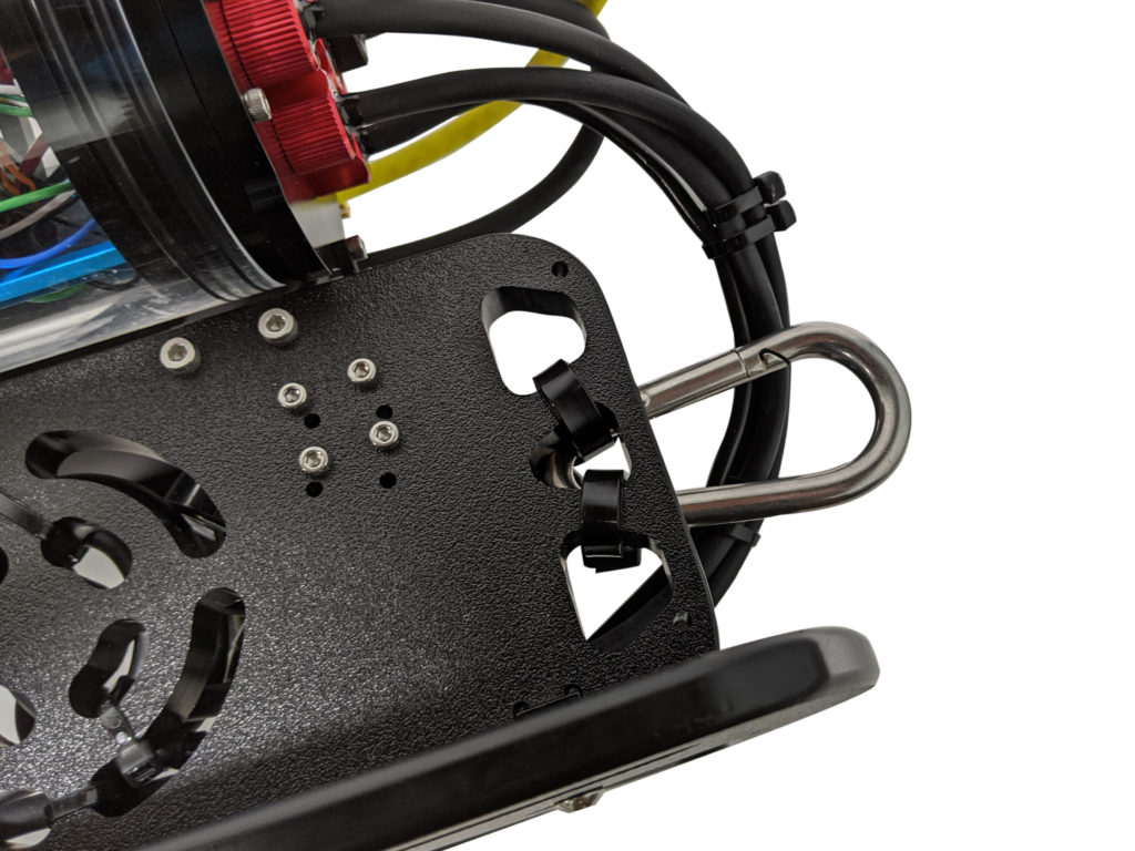
3. Using two new large black zip ties, attach the carabiner to the frame. Ensure the latch is able to open and close freely.
4. Reinstall the buoyancy block and fairing that had been removed in Step 1 of this section onto the ROV by installing the screws through the center panels and into the fairing.
Adjusting Ballast on the Frame
To adjust the amount or position of ballast on the frame you need the following parts and tools:
- 7 x 200g Ballast weights (from original BlueROV2 Kit)
- 7 x 8-16 Thread, 5/8” Long, Thread-Forming Screws
- 1 x #2 Phillips head screwdriver
To get the longest battery life and the best driving experience, it is important to have the ROV close to balanced from front to back in water and close to neutrally buoyant. After installation, the ROV may need to be re-trimmed based on your operating conditions. Trimming the ballast may involve a bit of trial and error.
Outland Technology Power Supply User Manual
After the hardware modifications are complete, please read the user manual on operation of the system as provided by Outland Technology:
OTPS User Manual 46-0013 Rev B3 (PDF) (Current)
OTPS User Manual 46-0013 Rev B2 (PDF) (Retired)
OTPS User Manual 46-0013 Rev A5 (PDF) (Retired)