
Newton Gripper Repair Guide
Introduction
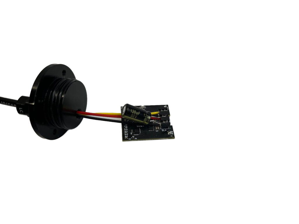
In this guide, we’ll explain how to replace the Newton Gripper motor, ESC, and power cable assembly. The guide is laid out so you can repair one or all of the components. Before proceeding, please ensure that you’ve contacted the Blue Robotics Support Team to verify that this is the best solution for the issue you’re encountering.
Taking the Gripper Apart
Tools You Will Need
- 2.0 mm hex driver
- M06 WetLink Bulkhead Wrench: BR-100977-006 or Soft touch pliers
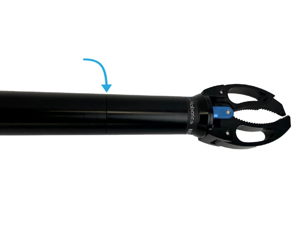
Let’s dive in! The Gripper can be separated into two main parts: the front housing (the jaws) and the rear housing (the part with the cable).
1. Twist the two parts counterclockwise to unfasten the front from the rear.
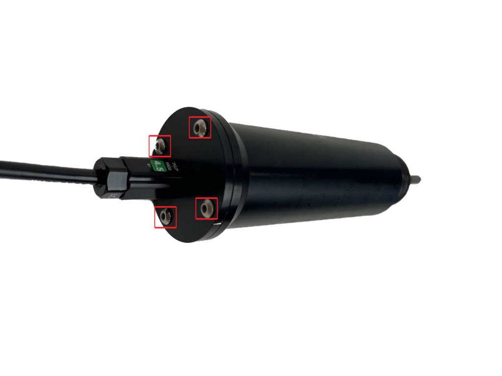
2. The motor and electronic speed controller (ESC) are in the rear housing. To access the motor, you must unfasten the four screws that secure the rear flange to the rear housing. You can also loosen the penetrator to facilitate the removal process if you’re replacing the power cable assembly.
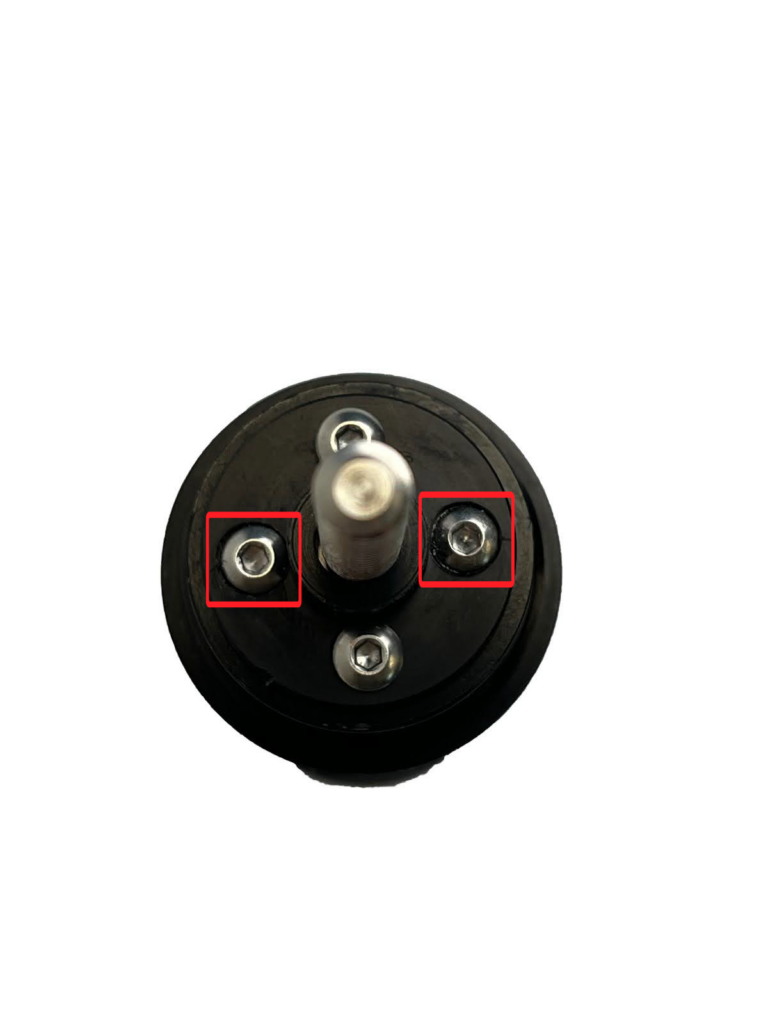
3. The motor is secured to the rear housing by two screws in the front. Unscrew the two recessed screws in the bumper on the front of the rear housing.
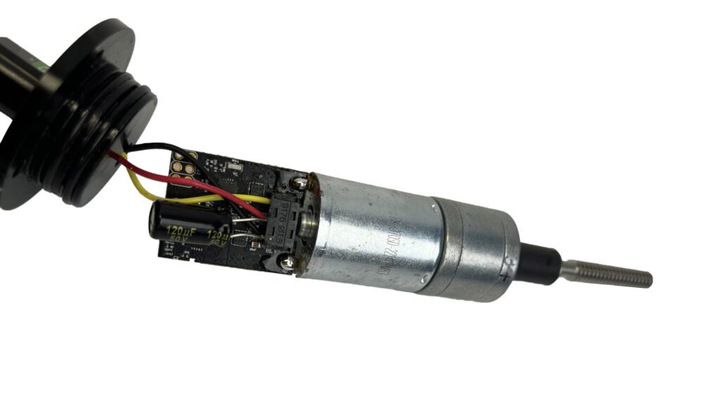
4. The rear flange cap can now be removed. Sometimes, this can be difficult because the O-rings can make a tight seal over time. Do not use anything metal to pry it off, it can result in irreparable damage. Instead, wiggle back and forth slightly while pulling and it should eventually come off. Take care not to pull too hard, the wires are attached internally. Once the flange is removed, you should have access to the internals.
Taking the Internals Apart
Parts and Tools You Will Need
- Small flathead screwdriver
- Soldering iron
- Solder
Break it down!
1. To desolder the motor and the ESC, apply heat to the solder joints with the solder-wet tip of a soldering iron.
2. Remove the IDC cap, gently prying the rear of it with a small flathead screwdriver.
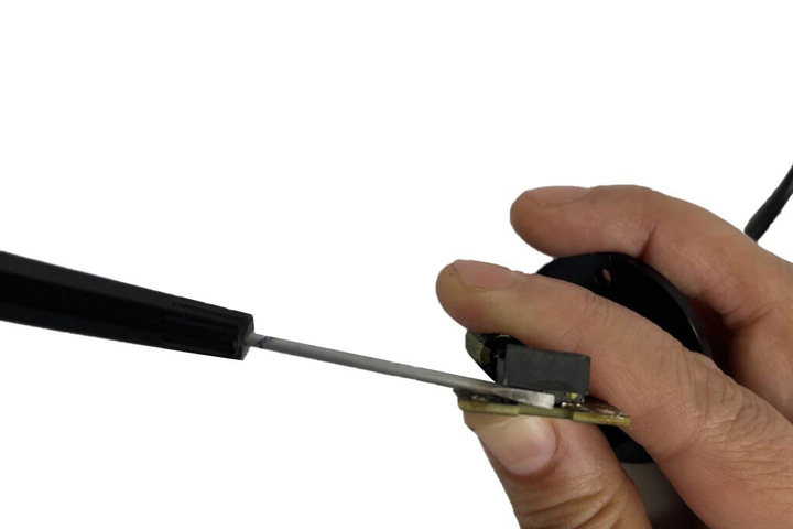
3. Remove the capacitor and pull the cable leads off the ESC IDC connector.
4. Fully unfasten the penetrator from the flange cap.
Now the internals are detached, and the cable can be replaced!
Cable Replacement
Parts and Tools You Will Need
- Cable Jacket Stripper
- Crimp Tool
- Heat gun
- PUR Subsea Cable – Lumen/Gripper Cable (3 conductors, 22 AWG)
- Wire cutters
- M06-4.5MM-LC
- M10-4.5MM-LC
- M06 WetLink Bulkhead Wrench: BR-100977-006 or Soft touch pliers
- 10-22AWG Wire Strippers
- 1 x Black shrink tube
- 1 x Female header pin
- 1 x Red shrink tube
- 2 x 18-22AWG spades
Lets get the cable prep started!
1. Cut cable to a length of about 40 inches. Prep each side of the cable as follows:
Device Side:
1. Strip 2.75 inches off one side of the cable jacket.
2. Install WLP-M06-4.5MM-LC.
3. Fasten the flange cap to the WLP. Don’t forget to add a greased O-ring between them.
ROV Cable end:
1. Strip 10.5 inches off the cable jacket.
2. Install WLP-M10-4.5MM-LC.
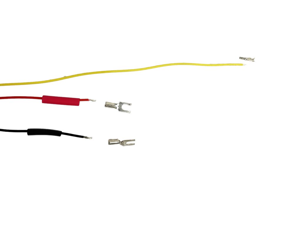
3. Cut the red and black wires to measure 5.5 inches. Do not cut the yellow wires!
4. Strip ¼ inch off the yellow, red, and black wires.
5. Crimp the yellow wire using a female header pin.
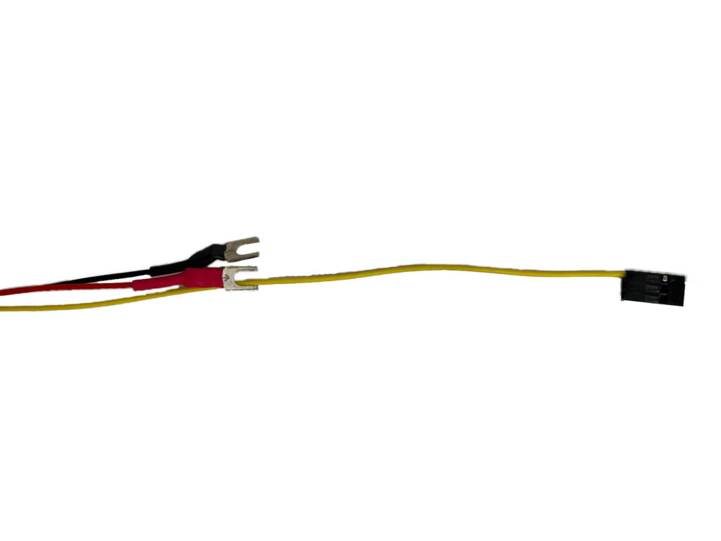
6. Insert red and black 1/8 heat shrink over the red and black wire, and crimp or solder the 18-22AWG spades.
7. Shrink the heat shrink, covering the spade’s stem with a heat gun.
8. Insert the female header pin into the left side of a header housing.
Installing the New ESC
Parts and Tools You Will Need
BR SKUs that don’t have a product page linked can be ordered by adding this Special Request item to your cart, enter billing/shipping information and specify the item SKUs and quantities needed in the customer notes. At check out, Request a Quote. A sales representative will return the quote with the total cost, including shipping and a payment link.
- ESC: BR-100410
- IDC (insulation-displacement contact) insertion tools:
Get your control on!
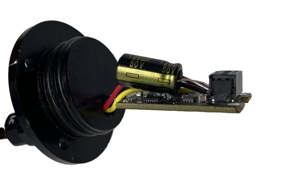
1. Punch in the yellow, red, and black wire leads with the IDC punch hand tool to the corresponding color label on the ESC.
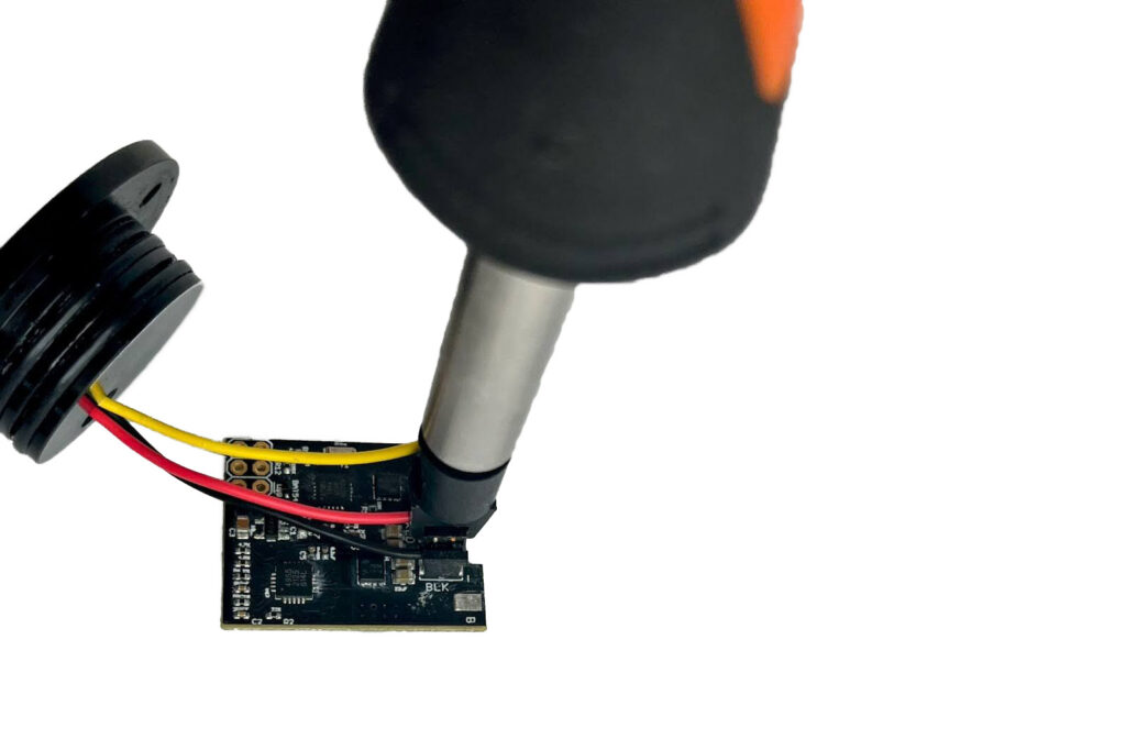
2. Add the capacitor on top of the red and black cable with the golden band on the negative/black side.
3. Install the IDC cap. To do this, you can remove the Kyocera tool bit from the Kyocera hand tool and gently massage the cap on.
Installing the New Motor
Parts and Tools You Will Need
- Motor: BR-100671
- Soldering iron
- Solder
Breathe life into the motor and grab on!
1. To desolder the motor and the ESC, apply heat to the solder joints with the solder-wet tip of a soldering iron.
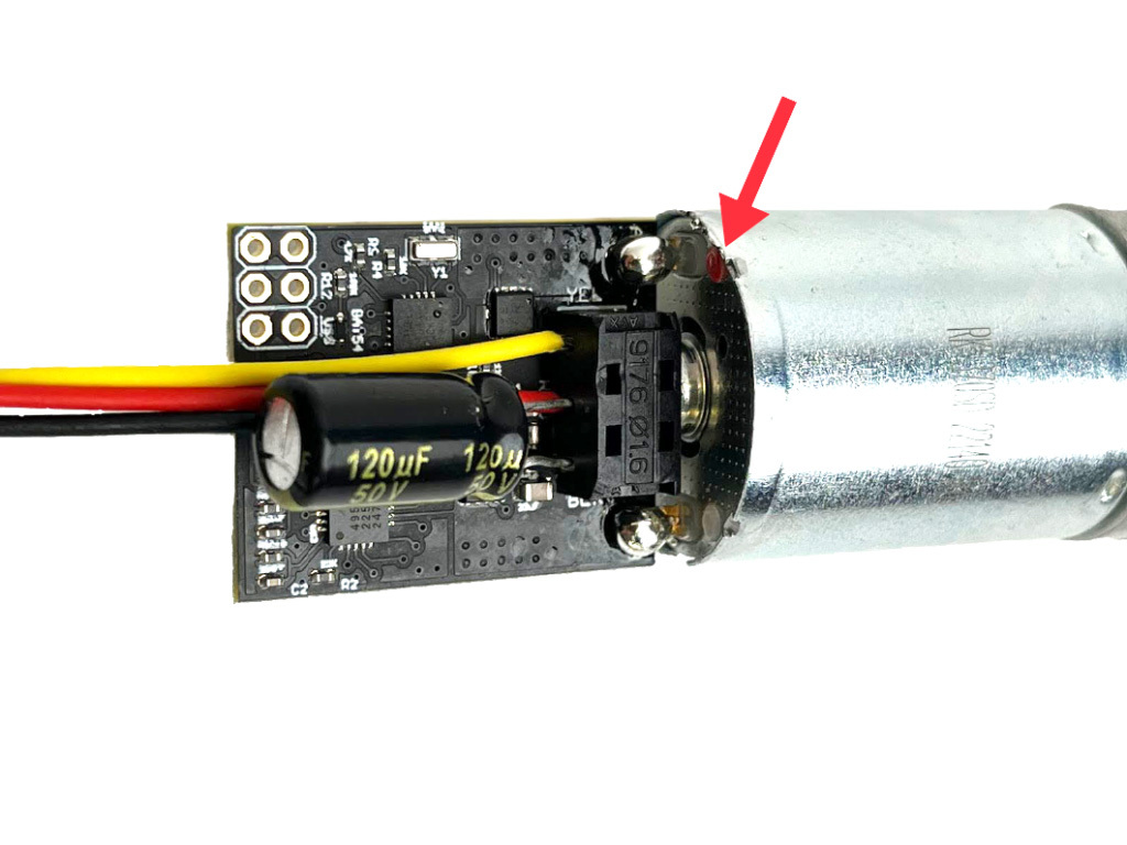
2. Solder Newton Gearmotor to Newton ESC—match the red dot to the solder pad labeled A.
Reassembly
It is advisable to spin test the motor before the Gripper is reassembled. Additionally, it is recommended to use Loctite 248 Threadlocker on the flange cap screws and Red Loctite 262 or 263 Threadlocker on the motor screws.
Troubleshooting
If the gripper fails to power up, check the solder between the motor and ESC and ensure you don’t have a cold solder joint. Apply 9–18V DC directly to the motor tabs. If the motor spins, there is a problem with the ESC. If the motor does not spin, the motor is faulty.
What did you think of this guide? Can we improve it? Let us know here!