
Integrating the Surveyor Multibeam Echosounder on the BlueBoat
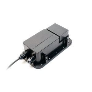
The Surveyor 240-16 Multibeam Echosounder is a compact, low-cost multibeam echosounder perfect for the BlueBoat and other small USVs. It has a depth range of 50 meters and a built-in IMU to provide pitch and roll compensation for accurate results, even in rough water. Paired with SonarView software, the Surveyor generates real-time 3D point clouds of the seafloor for bathymetric surveys and mapping.

This guide will show you how to install the Surveyor 240-16 on the BlueBoat.
Cerulean provides great documentation for the Surveyor 240-16 and SonarView software. Once your integration is complete, be sure to check out their guides for usage information and helpful tips.
Kit Contents
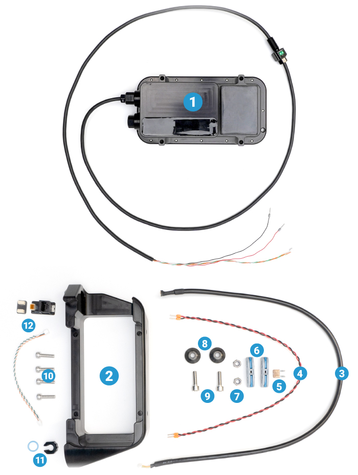
- 1 x Cerulean Surveyor 240-16 Multibeam Echosounder
- 1 x Surveyor 240-16 mounting bracket
- 1 x 600 mm JST GH to JST GH Ethernet extension cable (BR-103531)
- 1 x 400 mm power extension cable (BR-103533)
- 1 x 5A Mini Blade fuse (BR-101401-005)
- 2 x Inline snap connector (BR-103548)
- 2 x M6 nylon insert lock nut (BR-101258)
- 2 x BlueBoat Hull Mount Bushing
- 2 x M6x20 socket head cap screw (BR-102241)
- 4 x M5x18 socket head cap screw (BR-101191)
- 1 x M10 bulkhead nut & -013 O-ring (BR-100167-010)
- 1 x Twisted pair cable, JST GH coupler, RJ45 adapter (not used for installation)
Parts and Tools for Installation
In addition to the Surveyor 240-16 kit, you will need the following to complete the installation:
- 4 mm hex key (included in BlueBoat kit)
- 5 mm hex key (included in BlueBoat kit)
- Small (~2 mm) flathead (slotted) screwdriver
- M10 Bulkhead Wrench or 16 mm wrench
- Silicone grease (Molykote 111)
- Cable ties for cable management (not included)
Cable Routing Options
The Surveyor cable can be installed through the rear of the BlueBoat or through the top of the starboard hatch lid. Installing through the rear preserves the ability to fully disconnect the hatch lid assembly from the BlueBoat. Select the cable routing method that works best for your setup.
Cable routed through the stern of the boat.
Cable routed through the hatch lid.
To route the cable through the rear of the boat, follow the instructions in the Under Fairing Cable Routing section. To route the cable through the hatch lid, skip to the Through Hatch Lid Cable Routing section.
Under Fairing Cable Routing
For this section you will need:
- Surveyor with included bulkhead O-ring
- M10 Bulkhead Wrench or 16 mm wrench
- 4 mm hex key
- Silicone grease (Molykote 111)
1. Remove the starboard hatch lid assembly from the BlueBoat by disconnecting all cables, then set it aside.
2. Use the 4 mm hex key to remove the starboard side hull fairing screws and remove the fairing from the hull.
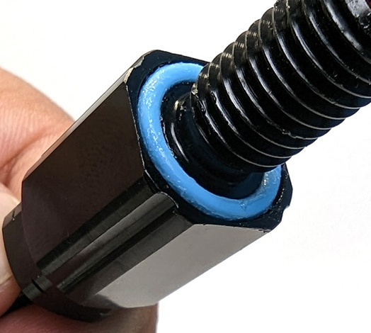
3. Apply a thin, even layer of silicone grease (Molykote 111) to the Surveyor bulkhead O-ring and install it in the groove on the underside of its penetrator.
4. The Surveyor bulkhead penetrator is installed in the M14 adapter penetrator. Use the M10 Bulkhead Wrench (or a 16 mm wrench) to remove the M10 penetrator blank from the M14 adapter penetrator.
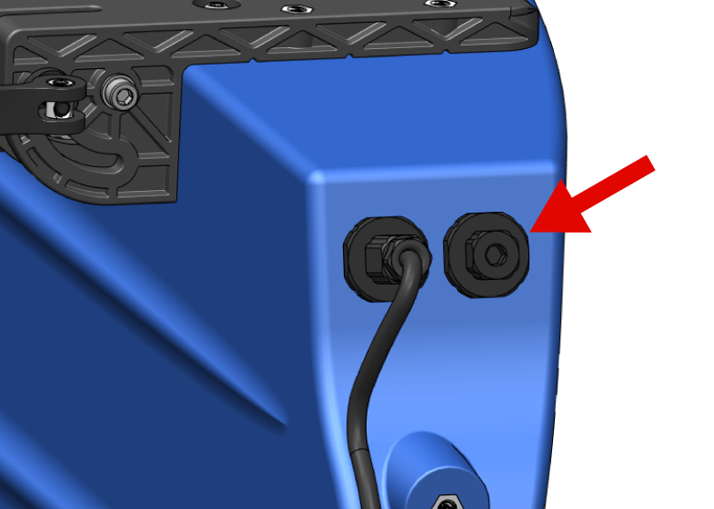
If desired, the entire M14 adapter can be removed temporarily to make installing the bulkhead easier. To do this, use an M14 Bulkhead Wrench (or a 20 mm wrench) to loosen the C-nut securing the adapter inside the hull. Be careful not to lose the O-ring that sits beneath the M14 adapter.
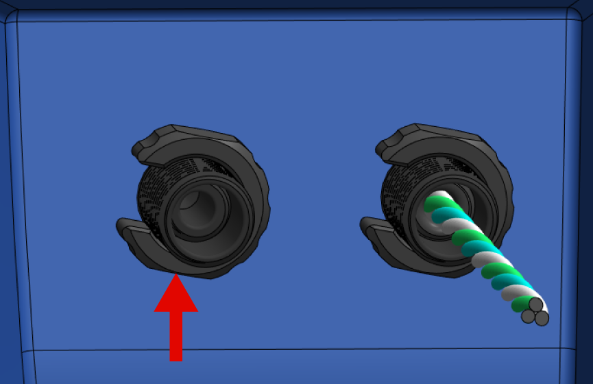
5. Install the Surveyor bulkhead penetrator into the adapter penetrator, and use the M10 Bulkhead Wrench (or a 16 mm wrench) to tighten it securely. The bulkhead C-nut is not used in this step.
If you removed the adapter penetrator earlier, reinstall it into the hull now.
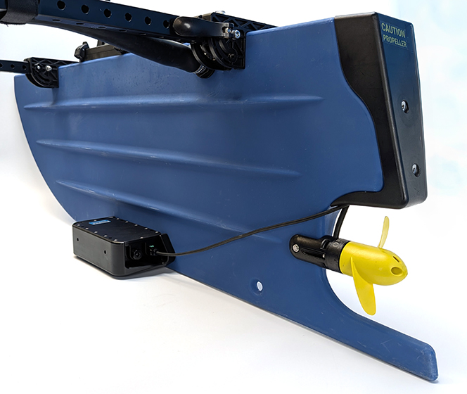
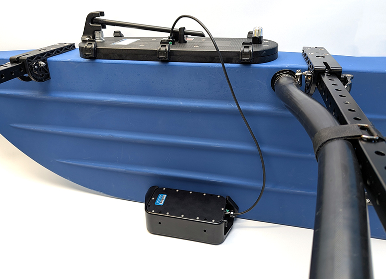
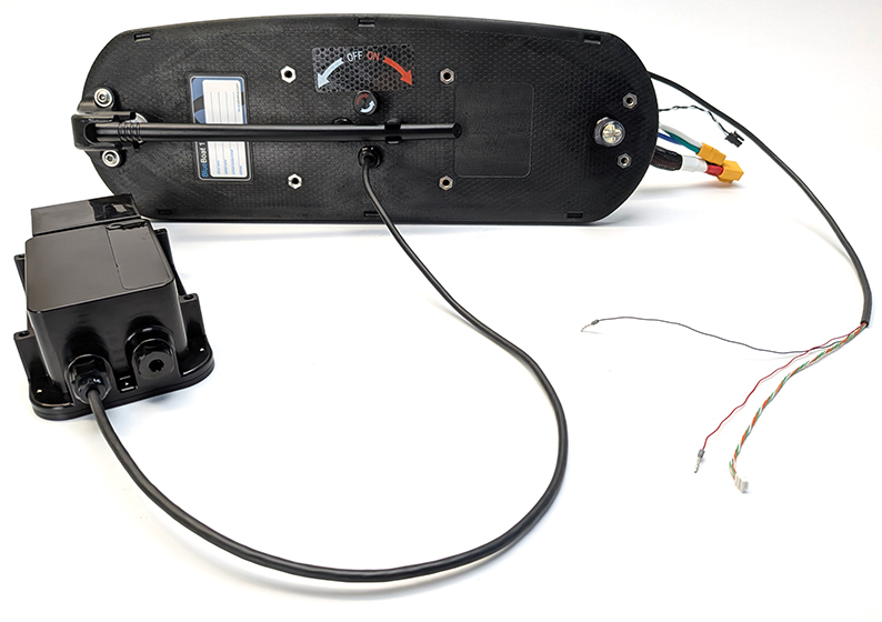
6. Reinstall the fairing on the starboard hull. Make sure the Surveyor cable runs through the cutout in the fairing, alongside the motor cable. At this point, your setup should look like this:
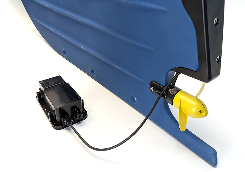
Proceed to the Cable Connections section.
Through Hatch Lid Cable Routing
These are the instructions to route the Surveyor cable through the hatch lid. If you have already installed the cable, you can skip this section and proceed to the Cable Connections section.
You will need:
- Surveyor with included bulkhead O-ring and C-nut
- M10 Bulkhead Wrench or 16 mm wrench
- 2.5 mm hex key
- Silicone grease (Molykote 111)
1. Remove the starboard hatch lid assembly from the BlueBoat by disconnecting all cables.
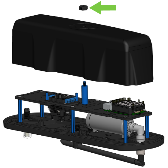
2. Remove the cover from the starboard hatch lid assembly by unscrewing the thumb nut.
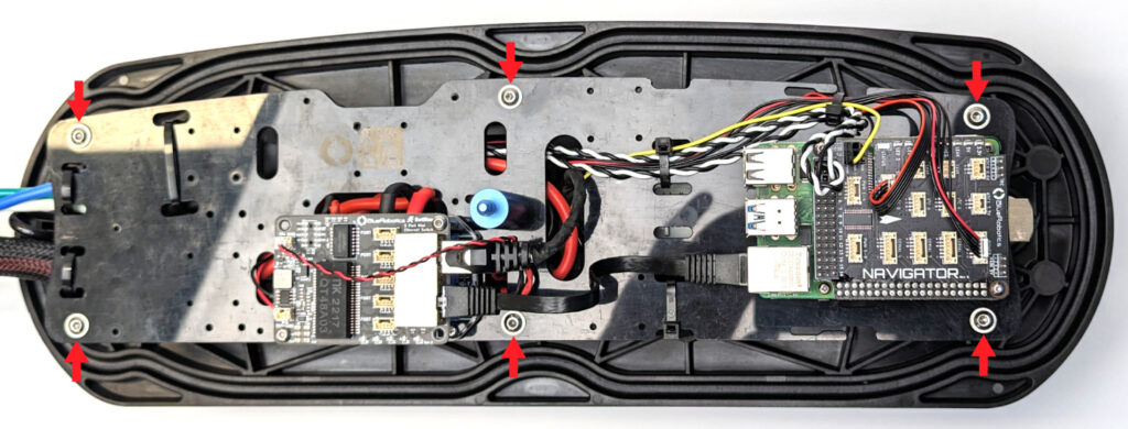
3. Use the 2.5 mm hex key to remove the six hex nuts from the electronics tray (on older boats these will be flange head screws). Move the electronics tray to the side but be careful not to pull on the wires too much.
4. Use the M10 Bulkhead Wrench or a 16 mm wrench to loosen the C-nut from one of the blank penetrators.
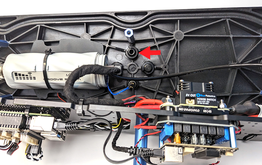
5. Apply a thin, even layer of silicone grease (Molykote 111) to the Surveyor Bulkhead O-ring and install it in the groove on the underside of the penetrator.
6. Install the Surveyor bulkhead penetrator into the hole and fasten the C-nut on the opposite side. Tighten it by hand, then use the wrench to fully secure it.
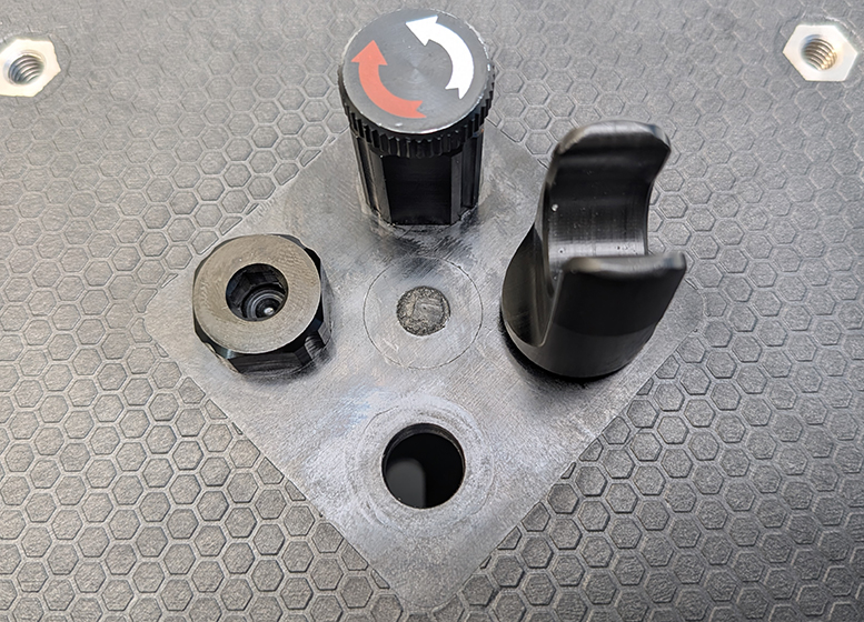
On older BlueBoats, the hatch lids have recesses shaped to hold the bulkhead in place and prevent it from turning. In this case, make sure the bulkhead is fully seated in the recess, and only use the wrench to turn the C-nut—do not attempt to rotate the bulkhead itself.
7. Mount the electronics tray back on the standoffs using the nuts or screws you removed earlier.
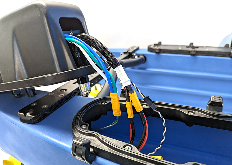
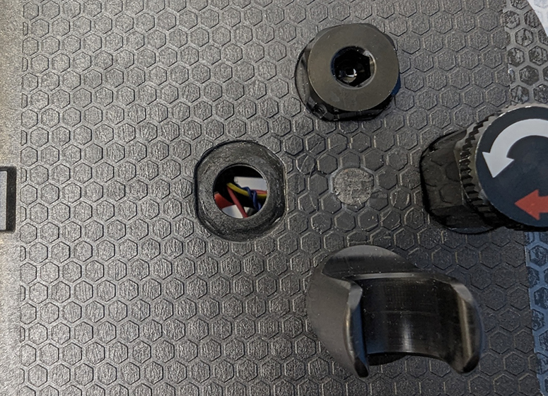
The hatch lid should now look like this:
Cable Connections
The Ethernet and power extension cables—along with the snap connectors—are only needed when the Surveyor cable is routed through the rear of the BlueBoat and you want to maintain the ability to quickly disconnect the starboard hatch lid from the boat.
If you don’t need the quick-disconnect feature, you can connect the cables directly to the electronics without using the extension cables.
You also don’t need the extension cables if the Surveyor cable is routed through the hatch lid.
- If you’re using the extension cables, follow the steps in Using the Extension Cables.
- If you’re connecting directly, follow the steps in Direct Cable Connection.
Using the Extension Cables
For this section you’ll need:
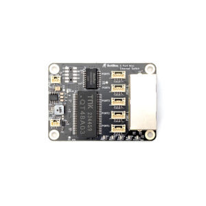
- 1 x Blue Robotics Ethernet Switch (if not installed already)
- 1 x 600 mm JST GH to JST GH Ethernet extension cable
- 1 x 400 mm power extension cable
- 1 x 5A Mini Blade fuse
- 2 x Inline snap connector
- Small (~2 mm) flathead (slotted) screwdriver
- Cable ties for cable management (not included)
1. Remove the cover from the starboard hatch lid assembly by unscrewing the thumb nut.
2. If you already have the Blue Robotics Ethernet Switch installed in the BlueBoat, you’ll need to temporarily unmount it from the fuse board. You don’t need to disconnect any wires—just remove the screws so you can access the fuse board underneath.
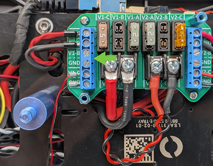
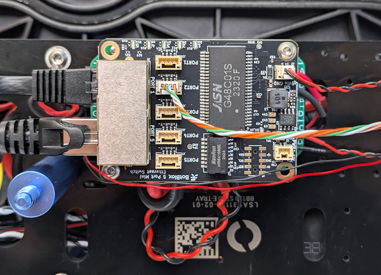
3. Connect the power extension cable to an available output on the V1 side of the fuse board. Do not use the V2 side, as it only supplies 5V power. Connect the black wire to the terminal labeled “GND”, and the red wire to the voltage output next to it. Use the small flathead screwdriver to loosen and tighten the screw terminals.
Install the included 5A fuse into the corresponding slot at the top of the fuse board.
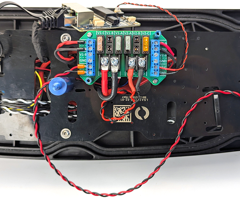
In this picture, the cable is connected to terminal V1-C, so the fuse is installed in the corresponding V1-C slot.
4. Now is a good time to install the Blue Robotics Ethernet Switch if you haven’t already. Follow the installation guide to complete the switch setup, then return to this guide when you’re done.
If you’ve previously installed the switch, go ahead and remount it to the fuse board at this time.
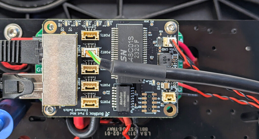
5. Connect the Ethernet extension cable to port 2, 3, or 4 on the switch. Do not use ports 1 or 5, as they are already in use.
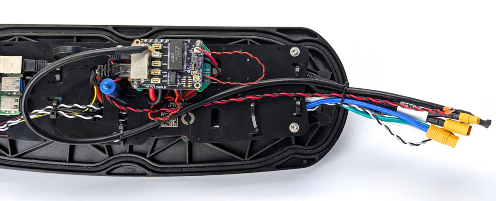
6. Use cable ties to secure the extension cables to the electronics tray and the main cable bundle. Position the extension cables to be about the same length as the other cables to keep everything tidy.
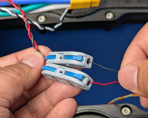
7. Install a snap connector on each of the power wires. To do this, pull up the lever, fully insert the wire into the hole, then close the lever to secure the wire in place.
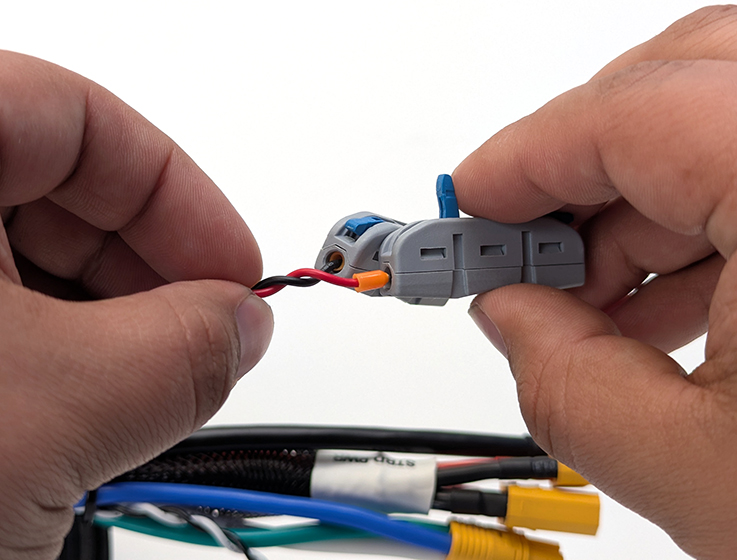
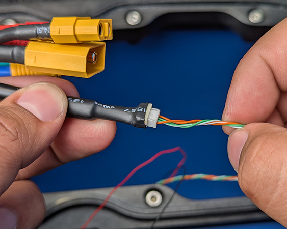
8. You can now connect the Surveyor cable to the extension cables. Connect the JST GH connector to the Ethernet extension cable, and connect the power wires to the snap connectors, making sure the wire colors match.
You can now reinstall the hatch lid cover and reconnect the remaining cables from the hatch lid to the BlueBoat.
Direct Cable Connection
For this section you’ll need:
- 1 x Blue Robotics Ethernet Switch (if not installed already)
- 1 x 5A Mini Blade fuse
- Small (~2 mm) flathead (slotted) screwdriver
- Cable ties for cable management
1. If you already have the Blue Robotics Ethernet Switch installed in the BlueBoat, you’ll need to temporarily unmount it from the fuse board. You don’t need to disconnect any wires—just remove the screws so you can access the fuse board underneath.
2. Connect the power wires to an available output on the V1 side of the fuse board. Do not use the V2 side, as it only supplies 5V power. Connect the black wire to the terminal labeled “GND”, and the red wire to the voltage output next to it. Use the small flathead screwdriver to loosen and tighten the screw terminals.
Install the included 5A fuse into the corresponding slot at the top of the fuse board.
In this picture, the cable is connected to terminal V1-C, so the fuse is installed in the corresponding V1-C slot.
3. Now is a good time to install the Blue Robotics Ethernet Switch if you haven’t already. Follow the installation guide to complete the switch setup, then return to this guide when you’re done.
If you’ve previously installed the switch, go ahead and remount it to the fuse board at this time.
4. Connect the Ethernet JST GH connector to port 2, 3, or 4 on the switch. Do not use ports 1 or 5, as they are already in use.
5. Use cable ties to secure the cable to the electronics tray to keep everything tidy.
You can now reinstall the hatch lid cover and reconnect the remaining cables from the hatch lid to the BlueBoat.
Installing SonarView and Calibrating the Surveyor
Before mounting the Surveyor on the BlueBoat, it must be calibrated on a level surface. To calibrate the Surveyor:
1. Install the starboard hatch lid back on the BlueBoat and connect all the cables if you haven’t already.
2. Connect a battery, power on your BlueBoat and BaseStation, and connect the system to your computer. If you’re not sure how to do this, check out the BlueBoat Software Setup Guide first.
3. Access BlueOS (the BlueBoat’s operating system) by typing 192.168.2.2 or blueos.local into a web browser address bar.
4. Connect the BlueBoat to a Wi-Fi network.
5. Installing extensions requires BlueOS version 1.1.0 or later. If your system is out of date, follow these instructions to update BlueOS then come back to this guide.
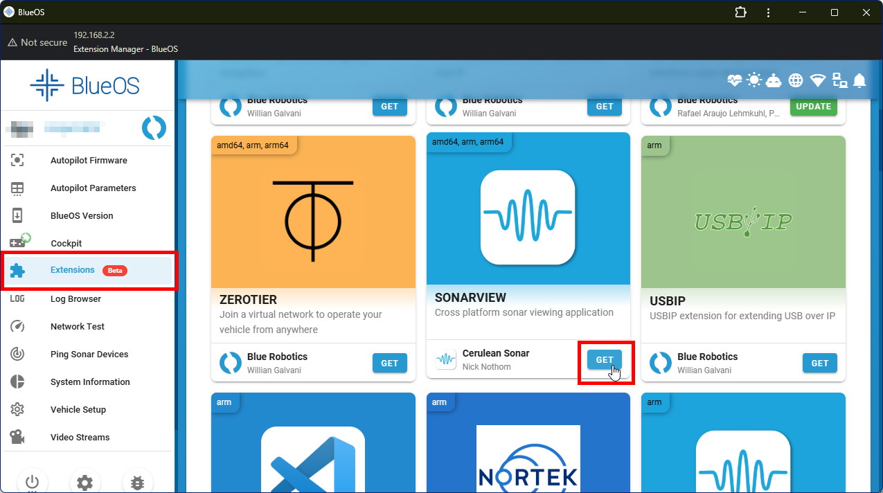
6. Go to the Extensions menu in BlueOS and install the SONARVIEW extension by Cerulean Sonar.
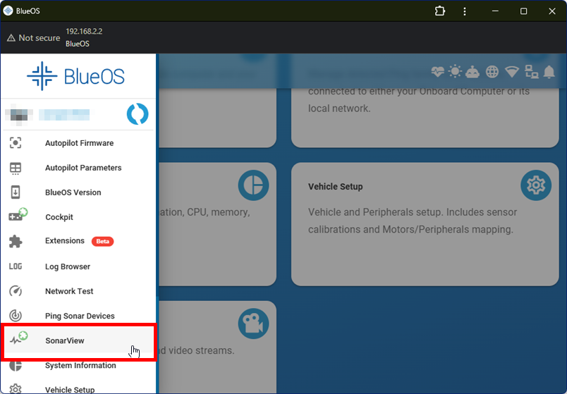
7. After the extension is installed, SonarView will appear in the left sidebar. Click it to launch SonarView.
8. Click on Device Discovery. The Surveyor should be listed here if everything is connected correctly. Click on CONNECT. If a firmware update is available, go ahead and update it.
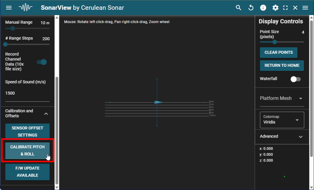
9. Expand the Advanced menu on the left side, then expand Calibration and Offsets. Place the Surveyor on a level surface then click on CALIBRATE PITCH & ROLL. Follow the onscreen instructions to finish calibration.
Once calibration is complete, you can finish the installation by mounting the Surveyor on the BlueBoat.
Mounting The Surveyor
To mount the Surveyor you will need:
- 1 x Surveyor 240-16 mounting bracket
- 2 x BlueBoat Hull Mount Bushing
- 2 x M6x20 socket head cap screw
- 2 x M6 nylon insert lock nut
- 4 x M5x18 socket head cap screw
- 4 mm hex key
- 5 mm hex key
1. Use the hardware from the bag labeled BlueBoat Mount Hardware and the 5 mm hex key to mount the bracket onto the starboard hull.
- Use the two forwardmost hull mounting points.
- If the nuts are difficult to install, tilt the boat to let gravity help—this will guide the nuts into the nut pockets and onto the bolt threads.
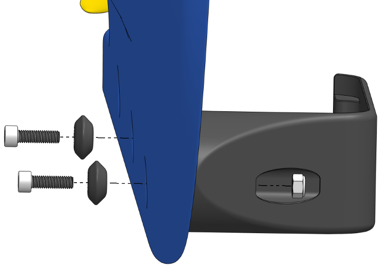
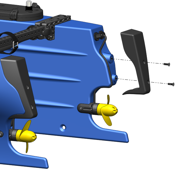
2. With the bracket installed, use the four M5x18 screws and 4 mm hex key to install the Surveyor in the bracket.

The BlueBoat and Surveyor are shown upside down in this image to better illustrate the screw locations.
Software Setup
The SonarView extension should already be installed at this point. If it isn’t, follow the instructions in the Installing SonarView section.
Adjust Message Stream Rates
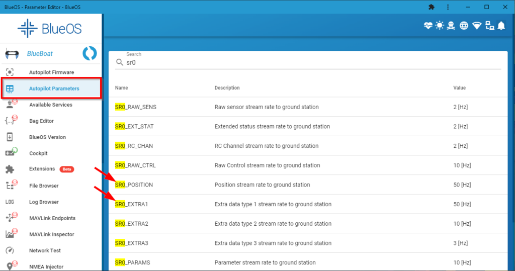
1. In BlueOS, click on Autopilot Parameters.
2. In the search box, type “sr0”. Find the SR0_POSITION and SR0_EXTRA1 parameters and set them both to “50”.
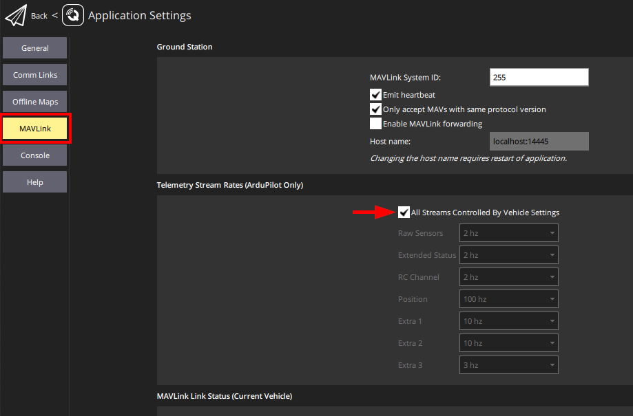
Configure QGroundControl
QGroundControl needs to be configured to allow the vehicle to control message rates.
1. Open QGroundControl, click the Q icon in the top left corner, then click Application Settings.
2. Click MAVLink on the left side, then enable All Streams Controlled By Vehicle Settings. Restart QGroundControl.
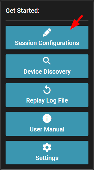
Creating a Session Configuration
1. From the SonarView main menu, click on Session Configurations.
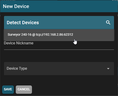
2. In the Session Configurations screen click on ADD DEVICE. In the next window, click on Detect Devices and select the Surveyor. Give it a device nickname, leave all the settings at default and click SAVE.
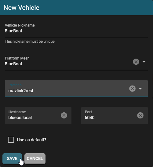
3. While still on Session Configurations screen, click on ADD VEHICLE. In the next window:
- Enter a vehicle nickname.
- Set the Platform Mesh to BlueBoat.
- Set the Protocol to mavlink2rest.
- Click SAVE.
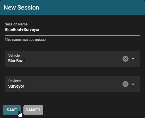
4. Click on ADD SESSION to make a new session. On the next screen, give the session a name, and use the drop downs to add the BlueBoat and Surveyor to the session. Click on SAVE when you are done.
That’s it! This session will now appear in the Device Discovery menu. Click on CONNECT next to the session then START to start using the Surveyor.
Next Steps
Head over to Cerulean’s documentation to learn more about using the Surveyor 240-16. A list of the most helpful links is below:
- Conducting Your First Survey
- Integration with Bathymetric Software (Reefmaster)
- CSV Export
- Viewing Point Clouds
- Replaying Saved Sonar Files
Feedback
We’re always working to make our guides, software, and user experience even better. If you have any ideas on how we can improve this guide, feel free to let us know here.