
Integrating the Sonoptix ECHO on the BlueROV2
Introduction
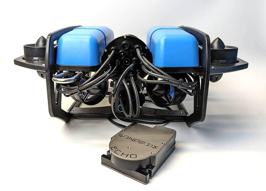
The Sonoptix ECHO is a high performance, multibeam imaging sonar with dual frequency capability. It hosts its own web-based user interface, meaning that you don’t have to download any software and it just works on any device or computer.
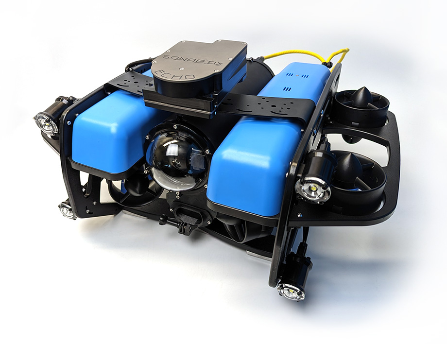
When purchased from The Reef by Blue Robotics, the Sonoptix ECHO comes equipped with a WetLink penetrator and connectors for easy installation and plug-and-play operation with the BlueROV2. This guide will show you how to install and operate the Sonoptix ECHO with a BlueROV2.
Hardware Installation
Parts and Tools
You will need:


You will also need:
- 1 x M10 Bulkhead Wrench
- 1 x 2.5 mm hex driver
- 1 x 3 mm hex driver
- 1 x #2 Phillips head screwdriver
- Silicone grease (Molykote 111)
- Medium-strength (blue) threadlocker such as Loctite 242 or 243.
- Zip ties for cable management
Preparing the BlueROV2
You will have to open up the BlueROV2 Electronics Enclosure and remove one of the penetrators to install the Sonoptix ECHO. To do this you will need:
- 1 x 2.5 mm hex driver
- 1 x M10 Bulkhead Wrench
If you are not sure how to perform any of the steps in this section, more detailed instructions for each operation are available in the Servicing the BlueROV2 section of the BlueROV2 Operation guide.
1. Make sure your BlueROV2 is completely powered off by disconnecting the battery.
2. Use the 2.5 mm hex to remove the M3x16 mounting screws that secure the enclosure mounting clips to the cradles, remove the PRV or vent plug, and remove the Electronics Enclosure tube from the Electronics Enclosure assembly.
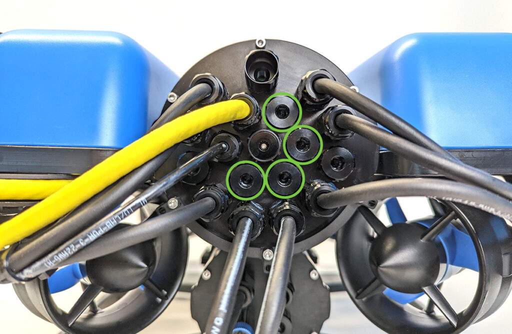
3. Choose one of the blank penetrators in the middle of the end cap and use the M10 Bulkhead Wrench to remove it.
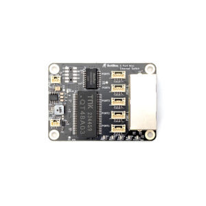
4. Install the Blue Robotics Ethernet Switch if you have not done so already. Follow the Ethernet Switch installation guide to install the Ethernet Switch in your ROV. Come back to this guide when you are done.
Installing the Penetrator
To install Sonoptix ECHO’s penetrator into the end cap, you will need the following parts and tools:
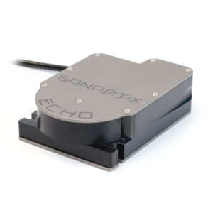
- 1 x Sonoptix ECHO
- 1 x M10 bulkhead nut (included with the Sonoptix ECHO)
- 1 x Bulkhead O-ring (included with the Sonoptix ECHO)
- 1 x Silicone grease (Molykote 111)
- 1 x M10 Bulkhead Wrench
1. Wipe the exterior surface of the end cap around the penetrator hole you previously removed the blank penetrator from. Ensure the area around the hole where the O-ring will sit is free of dust or debris.
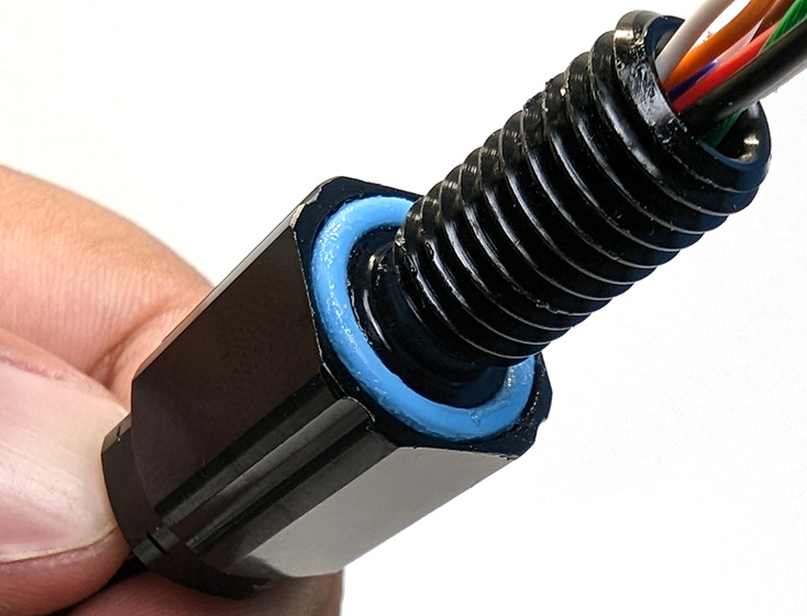
2. Inspect the penetrator O-ring to make sure it is not dirty or damaged.
3. Lubricate the O-ring with a thin layer of silicone grease and install it in the groove on the underside of the penetrator.
4. Install the penetrator in the hole and fasten the penetrator nut on the other side. Tighten the nut and bulkhead by hand until finger-tight. Use the Bulkhead Wrench to fully tighten the penetrator. The penetrator should no longer rotate in the hole and you should not be able to loosen it using your fingers when installed properly.
Wire Connections and Reassembly
For this step you will need:
- 1 x 150 mm JST GH to JST GH twisted pair cable (included with the Sonoptix ECHO)
- 1 x 4-pin JST GH to 4-pin JST GH adapter PCB (included with the Sonoptix ECHO)
- 1 x #2 Phillips head screwdriver
- 1 x 2.5 mm hex driver
- The M3 mounting screws you removed previously
- Silicone grease (Molykote 111)
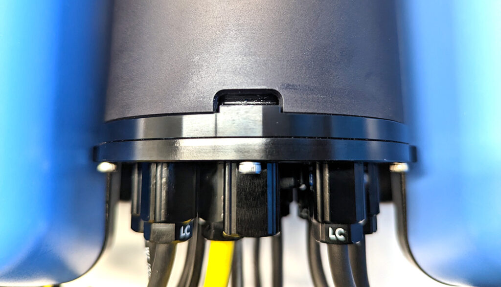
1. Use the #2 Phillips head screwdriver to connect the spade connectors at the end of the power wires to available screw terminals on the power terminal blocks. Connect the brown/white power wire (with black heat shrink) to the terminal block with the other black wires and connect the brown power wire (with red heat shrink) to the terminal block with the other red wires.
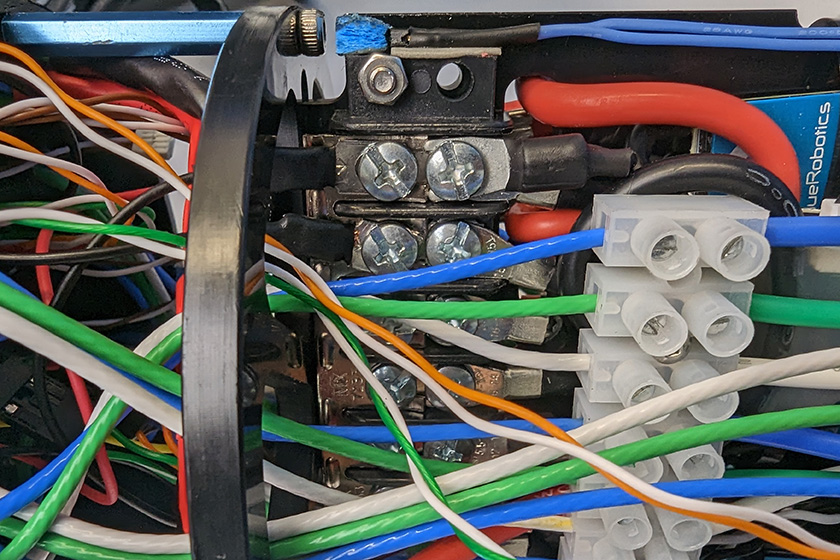
All the black power wires.
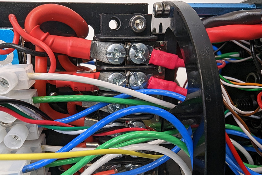
All the red power wires.
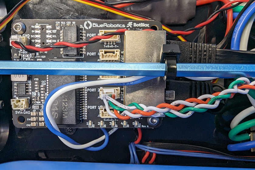
2. Connect the 4-pin JST GH adapter PCB to the 4-position JST GH connector at the end of the Sonoptix cable.
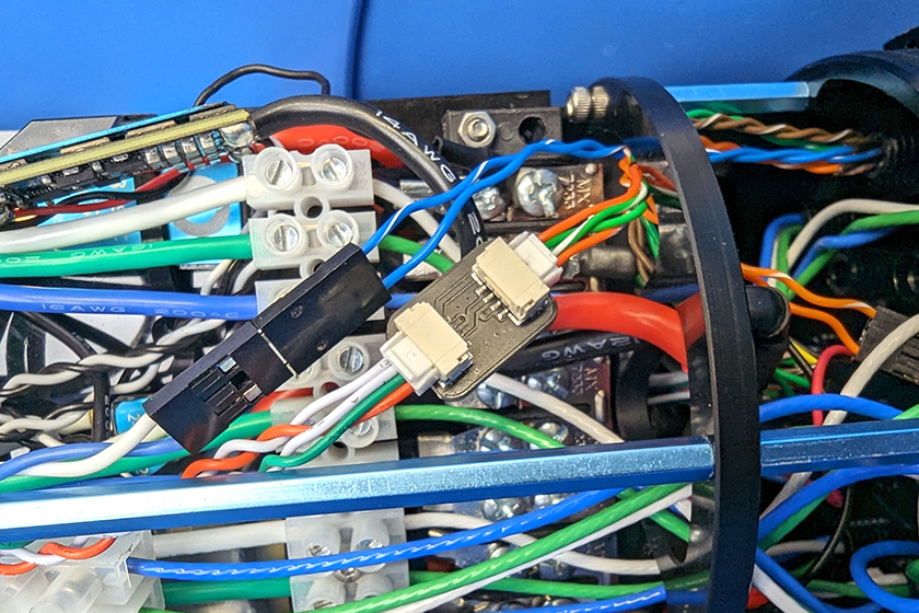
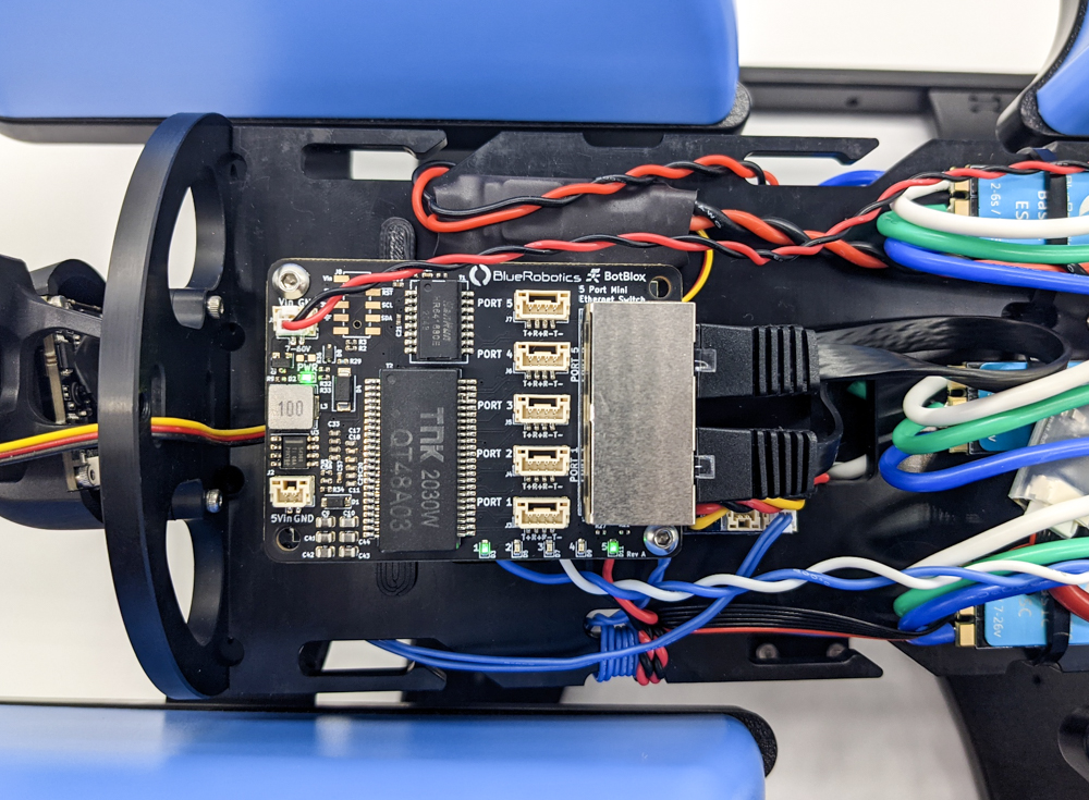
Connect the 150 mm JST GH to JST GH twisted pair cable to the adapter board then connect the other end to an open port on the Ethernet Switch. Do not use ports 1 or 5 as these are already in use.
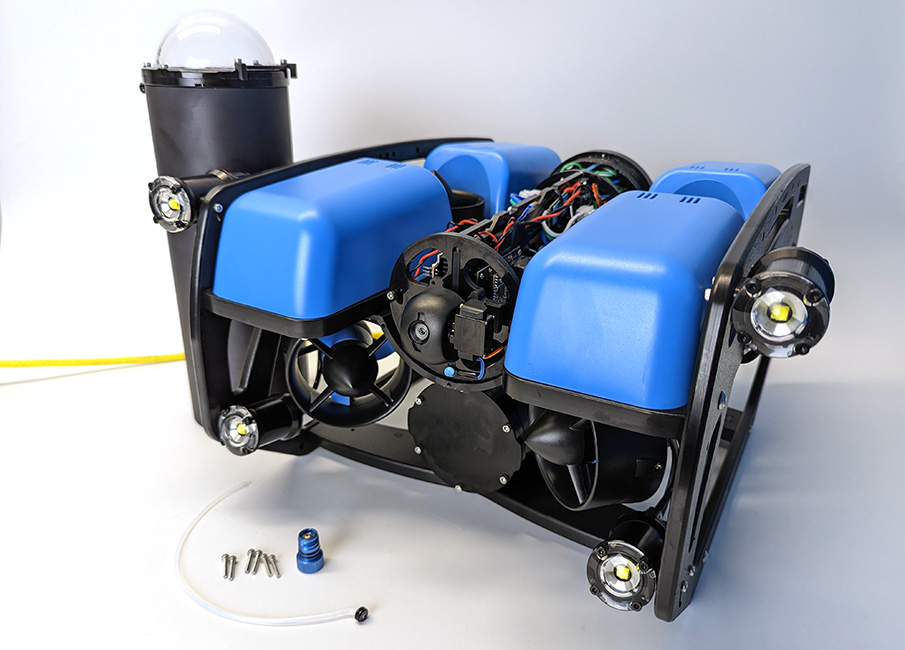
3. That completes all of the wire connections inside the ROV. You can now close up the ROV. Apply a thin coat of silicone grease to the two radial O-rings on the O-ring flange and the inner end of the tube.
4. Reinstall the tube and dome assembly onto the flange. If the ROV has a locking-style enclosure, ensure the rotation locking tab sits inside the slot in the tube.
5. Insert the locking cord through the slot. Older ROVs may not have a locking cord.
6. Reinstall the PRV or vent plug back in the bulkhead. Turn the plug clockwise until it stops to seal it.
7. Place the Electronics Enclosure on the enclosure cradles and line up the mounting clips with the screw holes on the cradles. Use the 2.5 mm hex to install the screws through the mounting clips and into the front and rear enclosure cradles
Mounting the Sonoptix ECHO to the BlueROV2 Frame
To mount the Sonoptix ECHO to the BlueROV2 frame, you will need:
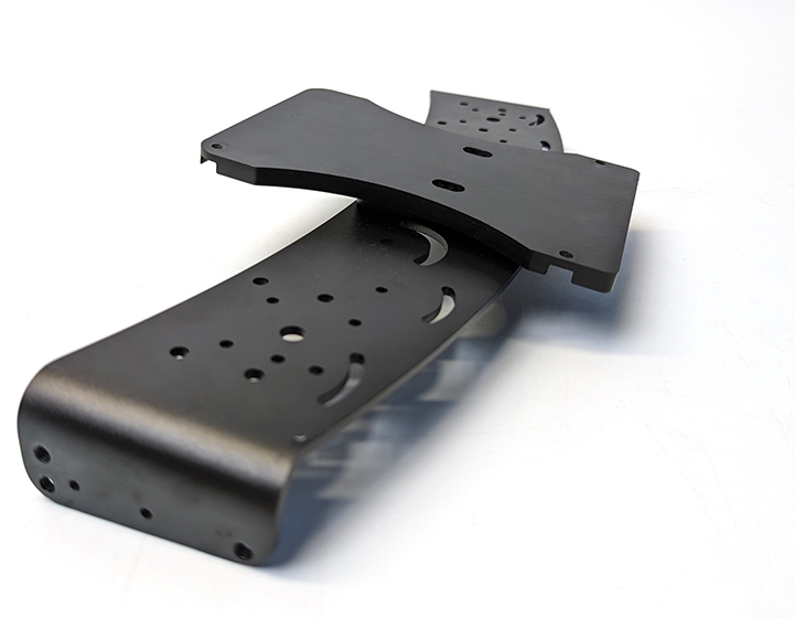
- 1 x BlueROV2 Roof Rack
- 1 x 5 Degree Mounting Bracket (included with the Sonoptix ECHO)
- 1 x 2.5 mm hex driver
- 1 x 3 mm hex driver
- 5 x M4x12 button head cap screws (included with the Sonoptix ECHO)
- 5 x M4 Nylon insert lock nut (included with the Sonoptix ECHO)
- 4 x M5x12 button head cap screws (included with the Roof Rack)
- 1 x Medium-strength (blue) threadlocker
1. Insert a lock nut in the two recessed holes of the mounting bracket. The flat side of the locking nut should sit against the flat surface.
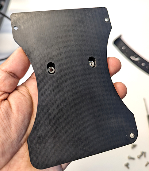
2. The BlueROV2 Roof Rack has three mounting location options for the Sonoptix ECHO. The middle mounting point is the default location but the side mounting points can be used if preferred.
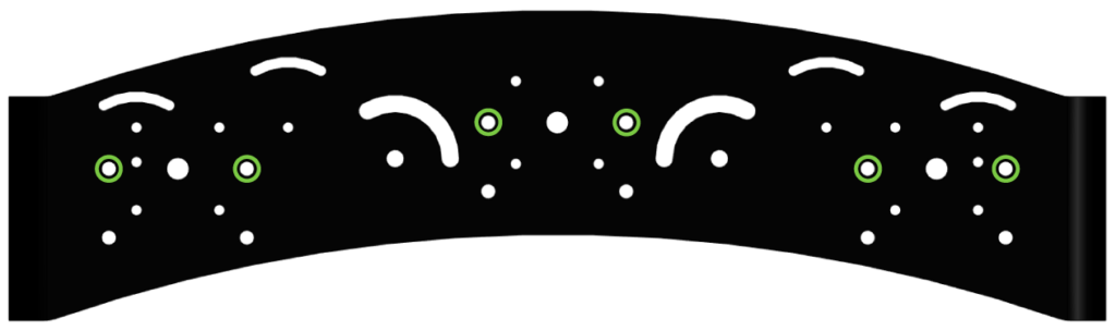
Choose a mounting location then use two M4x12 screws and the 2.5 mm hex driver to secure the mounting bracket to the rack.
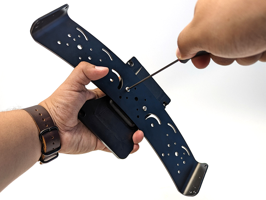
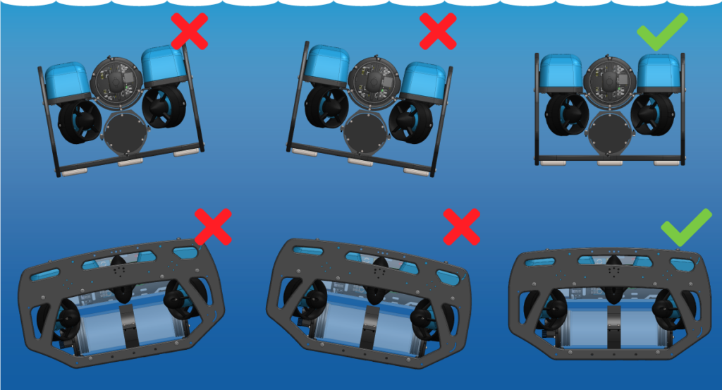
The mounting bracket should sit on top of the rack, with the angle sloping down toward the outward curved (convex) side of the rack.
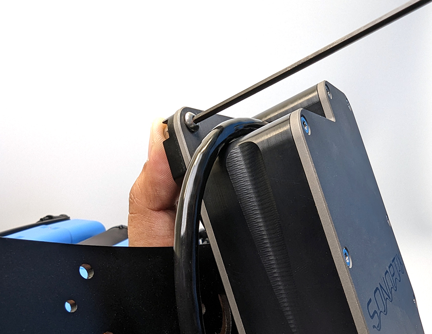
3. Take a moment to consider how you plan to route and secure the sonar cable to the frame, then route the sonar through the frame and into position.
4. Align the sonar mounting holes with the holes in the mounting bracket. Start with the mounting hole closest to the cable, insert a locking nut into the recessed mounting hole in the bracket. Use your finger to hold the nut while you secure the sonar using an M4x12 screw and the 2.5 mm hex driver. Repeat for the other mounting holes.
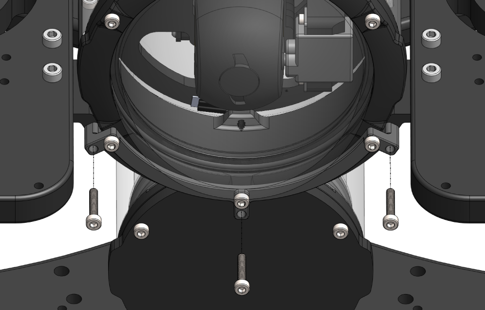
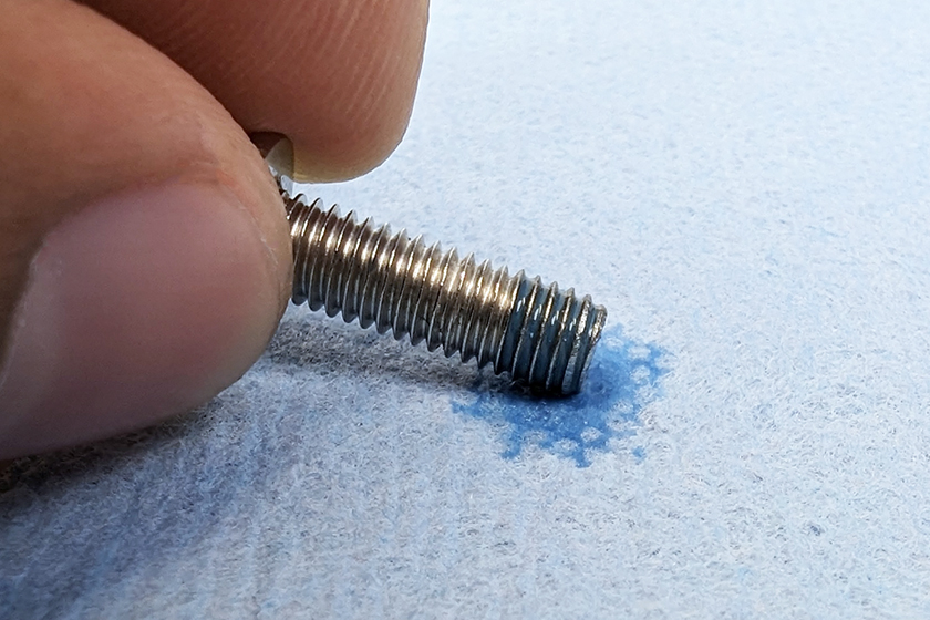
5. Apply one drop of threadlocker to the bottom of each M5x12 screw. Roll the screws around on a paper towel to evenly spread the threadlocker and remove any excess.
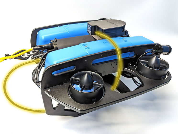
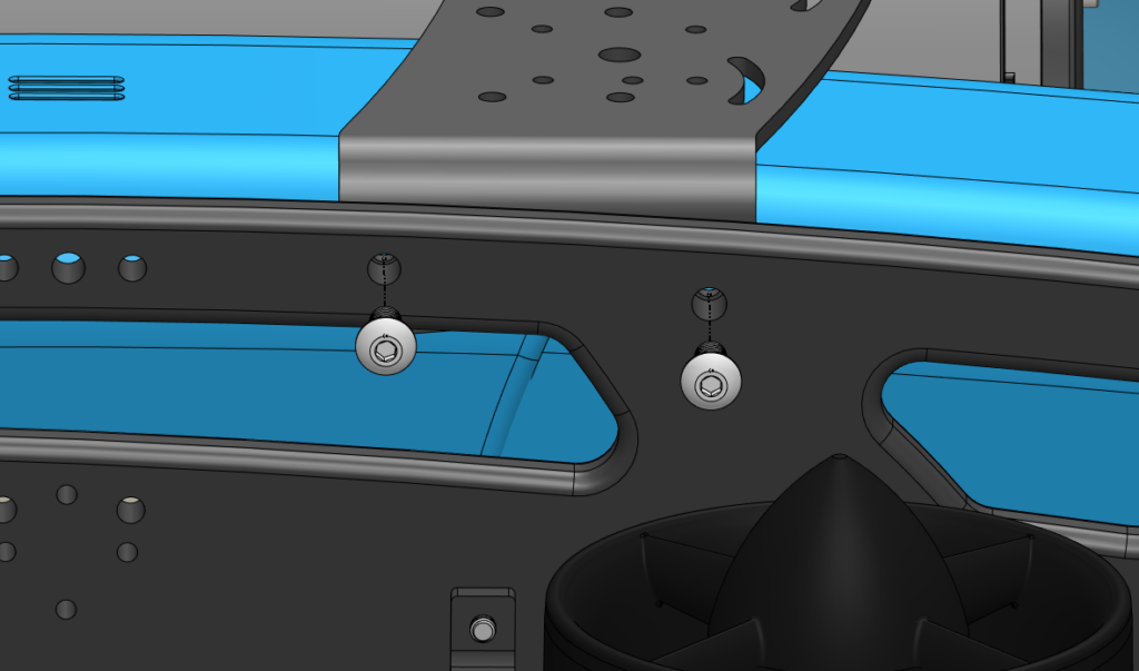
6. Align the Roof Rack mounting holes with the mounting holes in the BlueROV2 side panels. Use the upper set of rear mounting holes on the Roof Rack. The top of the Roof Rack should be level, not angled down, when mounted correctly. This puts the Sonoptix ECHO at an ideal 5° downward angle.
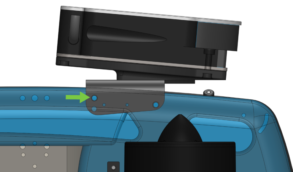
Use the M5x12 screws and the 3 mm hex driver to secure the Roof Rack to the BlueROV2 frame.
Cable Management
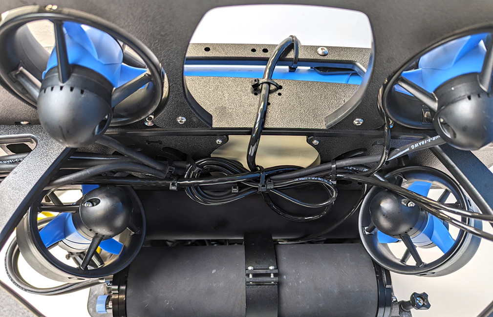
The goal of good cable management is to secure loose cable to the ROV frame to prevent it from getting damaged by the thruster propellers or getting caught on something during operation. Secure the cable to the frame using zip ties so there is no loose cable. Check that no cable can reach a thruster propeller after you have finished.
Adjusting the Ballast on the Frame
The sonar and rack add weight to the BlueROV2 frame, so the ROV ballast will need to adjusted to keep it neutrally buoyant and balanced in the water. Remove or relocate the ballast weights on the bottom of the frame to adjust the ballast. You can view complete instructions for adjusting the ballast in the Servicing the BlueROV2 section of the BlueROV2 Operation guide.
Using the Sonoptix ECHO
The Sonotix ECHO hosts its own user interface, so there is no need to download any additional software. You only need a web browser to access it.
1. Open your web browser and type 192.168.2.42 into the address bar to bring up the user interface. The user interface has three buttons:
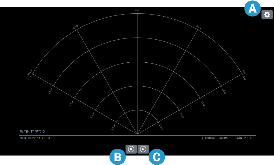
- A. Settings panel
- B. Record button to start and stop video recording
- C. Play button to start and stop pinging
2. Press the Play button to start pinging. The sonar will begin pinging and the button will change to a stop button. Press the stop button to stop pinging.
3. Press the Record button to record the sonar output. The record button will turn red while recording is in progress. Press the record button again to stop recording. The video file is automatically saved to whichever folder is designated as the “Downloads” or “Save to…” folder in your web browser settings.
4. Press the Settings button to open the settings panel overlay. The configurable settings are explained in the next section.
Sonar Settings
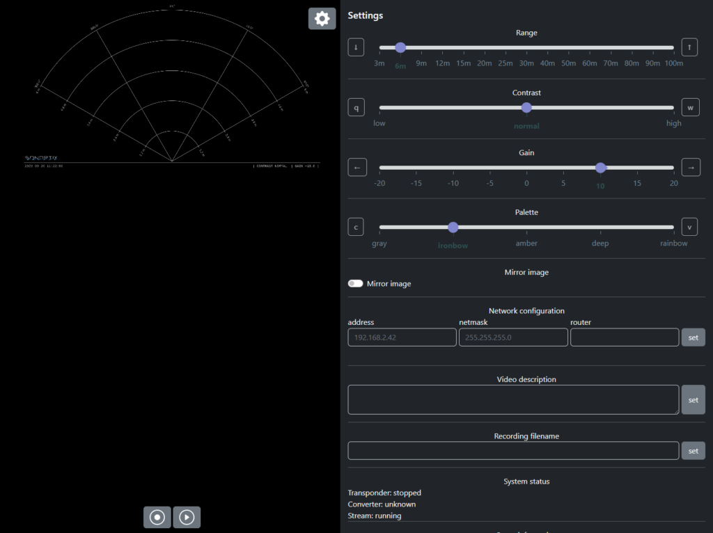
The following settings affect the way the sonar output is displayed. Each setting slider also displays shortcut keys that can be used to adjust the setting without opening the settings panel.
- Range: Adjusts the maximum distance from the sonar that is scanned and displayed in the sonar output. The sector angle for 3 m to 30 m range is 120°, the sector angle is reduced to 90° for 40 m to 100 m range.
- Gain: Adjusts the sensitivity of the receiver. Increasing the gain amplifies the received signals, making weaker echoes more visible. Excessive gain can also increase noise, making it harder to distinguish meaningful echoes from background noise. Decreasing the gain reduces sensitivity, which can help reduce noise but may make it harder to detect faint or distant objects.
- Contrast: Adjusts the sonar image contrast.
- Palette: Applies different color map options to the sonar image.
- Mirror Image: Flips the sonar output image. Use this setting if the sonar is mounted upside down.
Additional settings…
- Network configuration: Change the static IP configuration.
- Video description: The text entered here is displayed in a textbox in the lower corner of the sonar output.
- Recording filename: The text entered here is prepended to the filenames of recorded sonar video.
Updating Firmware
1. Download the latest firmware from this link and extract the SWU file.
2. Power up and connect the ROV with installed Sonoptix ECHO to your computer.
3. In a web browser, type 192.168.2.42:8081 in the address bar and follow the update instructions.
Feedback
We’re always working to make our documentation, instructions, software, and user experience even better. If you have any ideas on how we can improve this guide, feel free to let us know here.