
Changing Communications Interface on the Ping360
Introduction
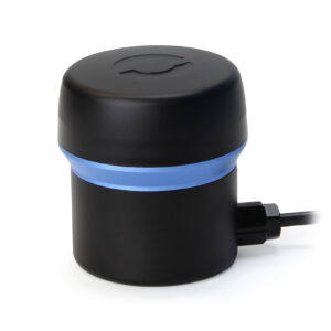
The Ping360 sonar is a mechanical scanning sonar. You can see echoes from objects like ropes, walls, dock pilings, rocks, shipwrecks, boats, and any other structures or objects that reflect sound waves. With that, you have reference points to navigate from, regardless of water visibility, and you can locate important features in the water quickly.
One of the unique features of the Ping360 is the ability to have user configurable communications interface types by changing a few wires around. This guide will show how to configure a Ping360 for USB, RS-485, or Ethernet communications.
Parts and Tools
You Will Need
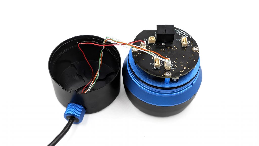
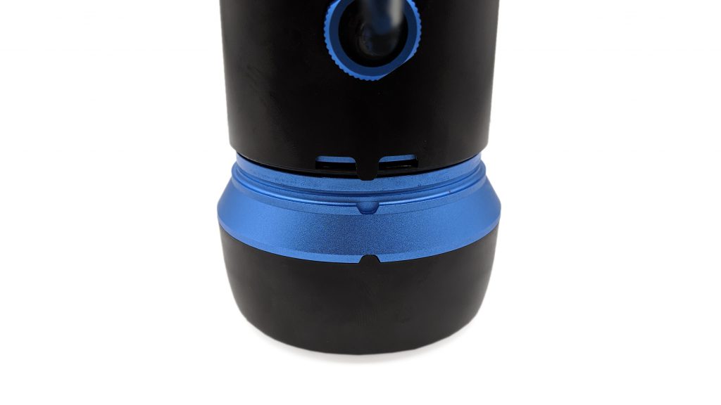
Separate the Ping360 Body
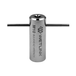
To remove the Ping360 body halves, you will need the following tool:
- 1 x M10 Bulkhead Wrench
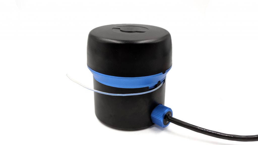
1. Remove the plastic cord retaining the two body halves together.
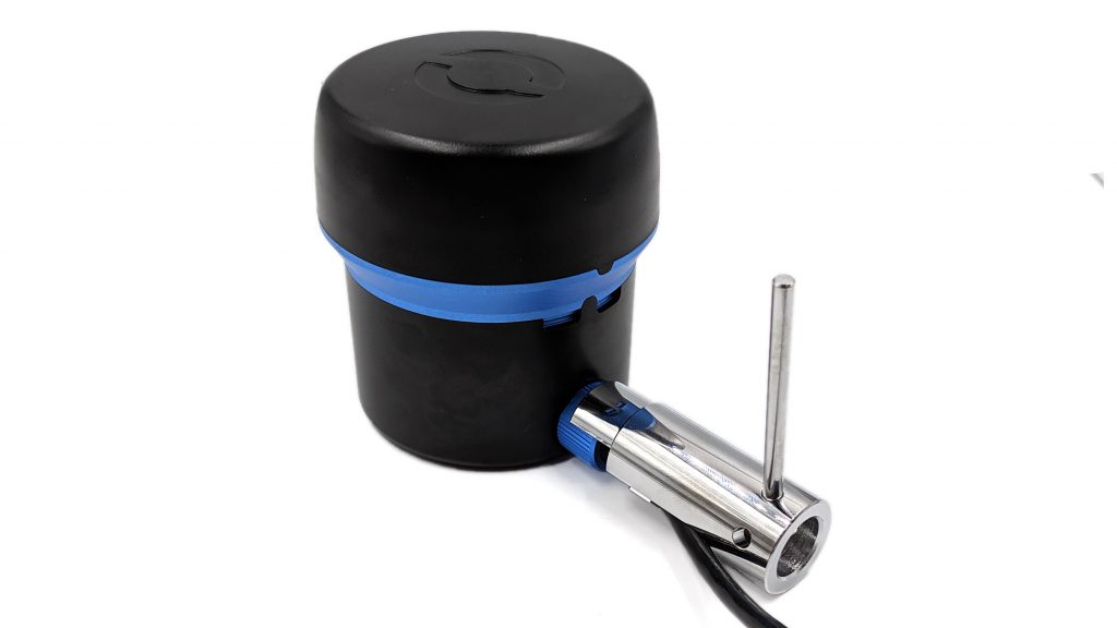
2. Using the M10 Bulkhead Wrench, loosen the penetrator just enough so that the air can be equalized.
3. Gently slide the two halves apart. Avoid opening the Ping360 with too much force that the wires are ripped out.
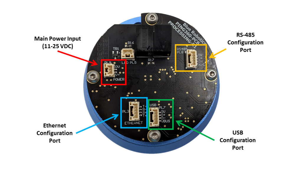
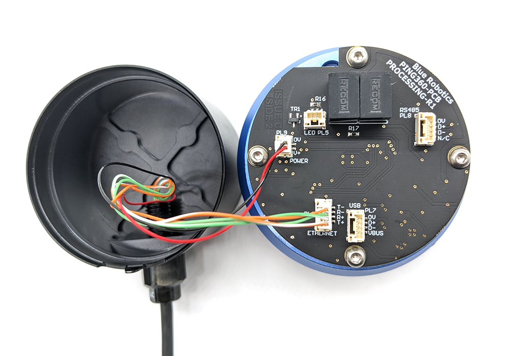
Ping360 Processor Board Overview
The following image shows the different interface port locations:
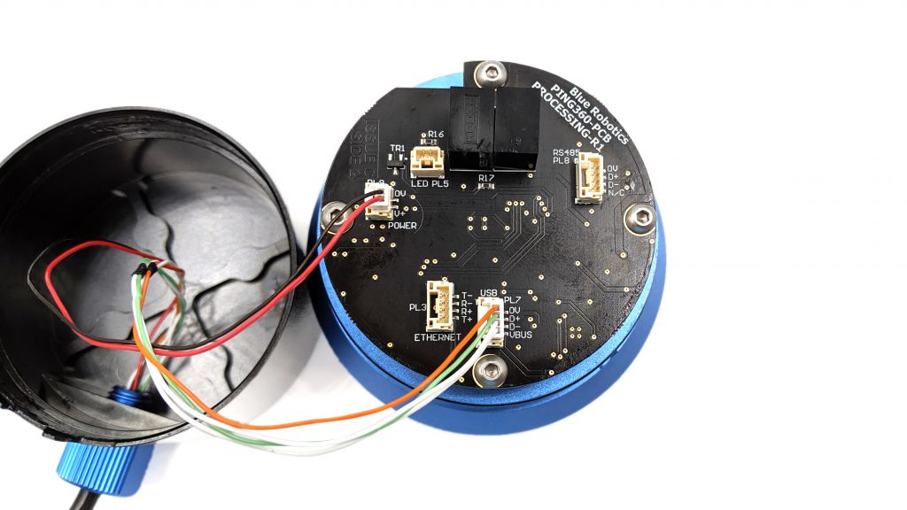
Processor Board - USB Configuration
Move the 4-pin JST-GH plug to the “USB” configuration port.
Ensure the plug firmly clicks into the receptacle.
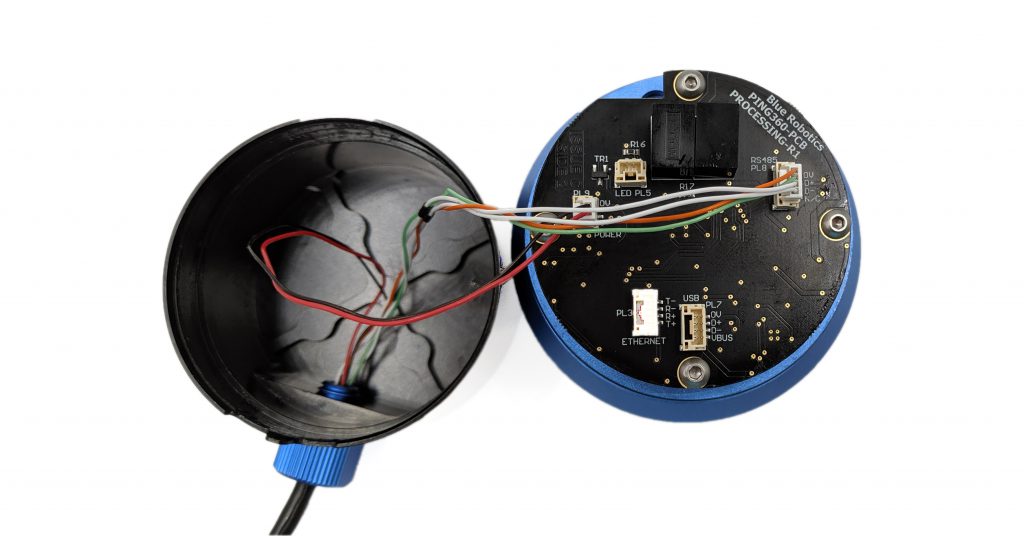
Processor Board - RS-485 Configuration
Move the 4-pin JST-GH plug to the “RS485” configuration port.
Ensure the plug firmly clicks into the receptacle.
Processor Board - Ethernet Configuration
Move the 4-pin JST-GH plug to the “ETHERNET” configuration port.
Ensure the plug firmly clicks into the receptacle.
Reassemble Ping360
1. Gently slide the upper head assembly onto the base with the penetrator loose so air can escape.
2. Slide the plastic cord in its channel to hold the two halves together.
2. Using the Bulkhead Wrench, tighten the penetrator so it is “hand tight”.
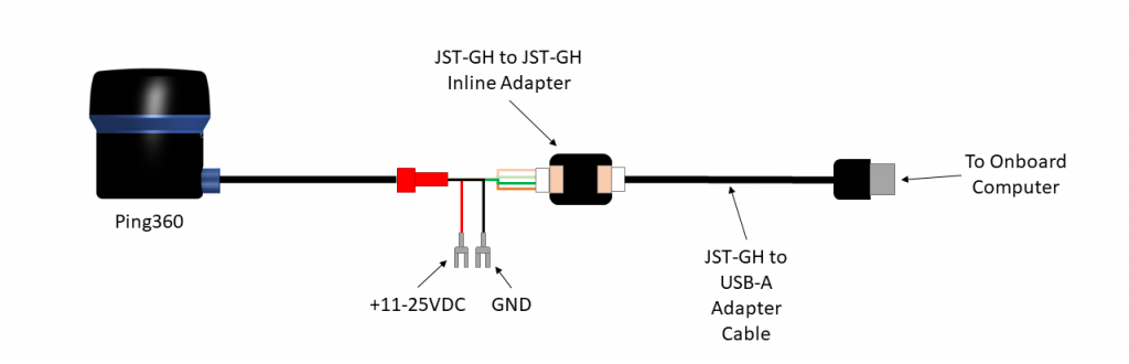
Wiring Connections - USB Configuration
You Will Need
- 1 x 4-pin JST-GH to 4-pin JST-GH adapter PCB (included with Ping360)
- 1 x 4-pin JST-GH to USB-A adapter (included with Ping360)
1. Connect the power wires (red and black wires) into open screw power terminals (11–18 VDC).
2. Plug the JST-GH to JST-GH inline connection board into JST-GH connector coming from the Ping360.
3. Plug the JST-GH to USB-A cable into the other end of the JST-GH to JST-GH inline connection board.
4. Plug the JST-GH to USB cable (USB side) into a computer.
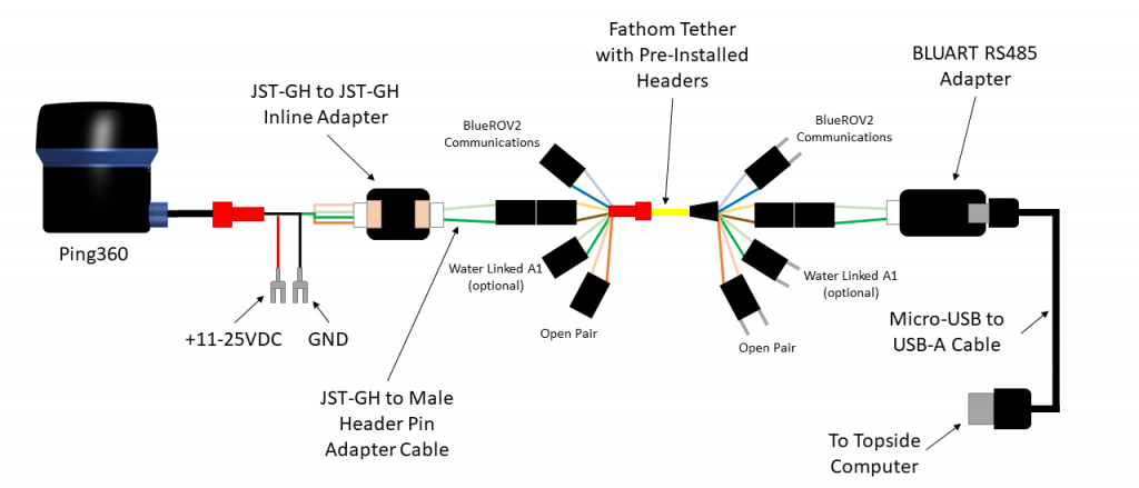
Wiring Connections - RS-485 Configuration
You Will Need
- 1 x 4-pin JST-GH to 4-pin JST-GH adapter PCB (included with Ping360)
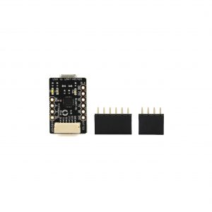
- 1 x 4-pin JST-GH to male header pin adapter cable (included with Ping360)
- 1 x 4-pin JST-GH to female header pin adapter or 2 x 0.1″ male-female jumper wires (not included)
1. Connect the power wires (red and black wires) into open screw power terminals (11–18 VDC).
2. Plug the JST-GH to JST-GH inline connection board into JST-GH connector coming from the Ping360.
3. Plug the 4-pin JST-GH to male header pin adapter into the JST-GH to JST-GH inline connection board.
4. Plug the male header pin adapter into an unused twisted wire pair on the tether.
5. Plug a 4-pin JST-GH to female header pin adapter or 2x 0.1″ male-female jumper wires into the corresponding unused twisted wire pair coming from the FXTI tether pigtail.
6. Plug a 4-pin JST-GH to female header pin adapter or 2x 0.1″ male-female jumper wires into the RS-485 TX/RX pins on the RS485 side of the BLUART.
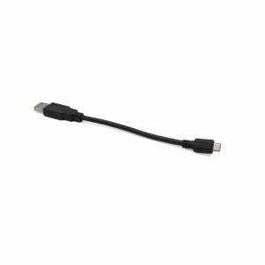
7. Plug the BLUART into a computer using a Micro-USB to USB-A cable.
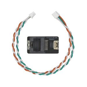
Wiring Connections - Ethernet Configuration
You Will Need
- 1 x Ethernet Cable (not included)
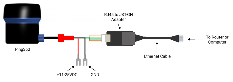
1. Connect the power wires (red and black wires) into open screw power terminals (11–18 VDC).
2. Plug the JST-GH connector coming from the Ping360 into the JST-GH connector on the RJ45 to JST-GH Adapter Board.
3. Plug an Ethernet cable into the RJ45 jack on the RJ45 to JST-GH Adapter Board.
4. Connect the other end of the Ethernet cable to a router or your computer.
Configure Network Settings
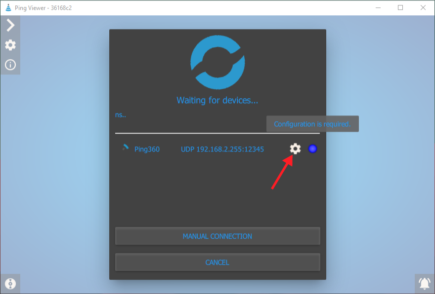
Make sure you are using Ping Viewer version 2.4.1 or newer. Configure the Ping360 Network settings from the Ping Viewer device manager screen.
- The Ping360 is configured as a DHCP client by default and will be assigned an IP address automatically when connected to a DHCP server such as a router. No additional configuration is necessary.
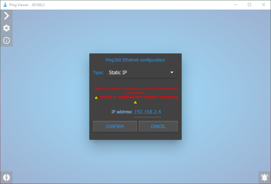
- The Ping360 IP address can also be configured manually by opening the network configuration menu and selecting Static IP.
- To connect the Ping360 directly to your computer:
- If the Ping360 is configured as a DHCP client, set your computer’s network configuration to automatic IP (DHCP).
- If the Ping360 is configured with a static IP address, set your computer to a static IP address on the same subnet.
- To use the Ping360 in Ethernet configuration with a BlueROV2, set the Ping360 to a static IP address on the 192.168.2._ subnet. The default 192.168.2.4 should work fine in most cases.
Troubleshooting
USB Configuration
1. Ensure the power and data wires are correctly plugged into their respective ports (POWER, USB) on the Ping360 processor board.
2. Ensure the power wires are correctly installed (positive and negative) into the power source. Ping360 does not have any reverse polarity protection and the Processor Board will be damaged if powered incorrectly.
3. Ensure the JST-GH connectors are plugged firmly into their receptacles. There will be a mechanical “click”.
4. Check to make sure you have the most recent stable release of Ping Viewer.
5. Contact our support team for further troubleshooting recommendations.
RS485 Configuration
1. Ensure the power and data wires are correctly plugged into their respective ports (POWER, RS485) on the Ping360 processor board.
2. Ensure the power wires are correctly installed (positive and negative) into the power source. Ping360 does not have any reverse polarity protection and the Processor Board will be damaged if powered incorrectly.
3. Ensure the JST-GH connectors are plugged firmly into their receptacles. There will be a mechanical “click”.
4. Try reversing one of the header pin connectors.
5. Check to make sure you have the most recent stable release of Ping Viewer.
6. Contact our support team for further troubleshooting recommendations.
Ethernet Configuration
1. Ensure the power and data wires are correctly plugged into their respective ports (POWER, ETHERNET) on the Ping360 processor board.
2. Ensure the power wires are correctly installed (positive and negative) into the power source. Ping360 does not have any reverse polarity protection and the Processor Board will be damaged if powered incorrectly.
3. Ensure the JST-GH connectors are plugged firmly into their receptacles. There will be a mechanical “click”.
4. Check to make sure you have the most recent stable release of Ping Viewer.
5. Check to make sure the Ping360 network settings have been configured correctly in Ping Viewer.
6. If you have a firewall enabled, create an exception rule to allow Ping Viewer through the firewall.
7. Try pinging the Ping360 at the configured IP address. If there is no response, check the network configuration.
8. Be sure that your computer’s network interface is configured as automatic IP (DHCP) if the Ping360 is in DHCP client mode, or with a static IP address if the Ping360 is configured with a static IP address. Be sure that your computer’s network interface IP address is using the same subnet as the device.
9. Contact our support team for further troubleshooting recommendations.
Feedback
We’re always trying to make our documentation, instructions, software, and user experience better. If you’d like to leave feedback about how we can make this guide better, let us know here.