
BarXT High-Resolution Depth/Pressure Sensors Guide
The BarXT Extended Submersion Depth/Pressure Sensors measure pressure, depth, and temperature underwater. These sensors require minimal maintenance and can stay submerged for extended periods. Our sensors are available in four models covering depths from 20 to 1000 meters.
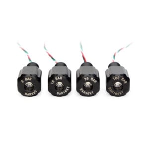
Installing the BarXT Sensor
The BarXT sensor works by exposing a “sensing face” to the water while keeping your electronics safe and watertight.
The sensor should not be fully submerged on its own. It is designed to be installed through a flat mounting surface, such as an enclosure or case. A rubber O-ring sits in a groove on the underside of the sensor bulkhead. When the bulkhead is installed and tightened, the O-ring is compressed against the surface, creating a watertight seal.
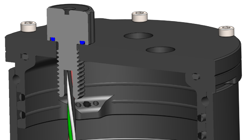
BarXT sensor installed through an enclosure end cap.
The BarXT sensors use the M10 bulkhead penetrator form factor and can be installed in any M10-size hole in a Blue Robotics Watertight Enclosure, Watertight Box, or other device.
Installation Procedure
1. Inspect the included O-ring; it should be clean and free of dents, cuts, or damage.
2. Apply a thin layer of silicone grease (such as Molykote 111) to the O-ring and place it in the groove on the underside of the bulkhead.
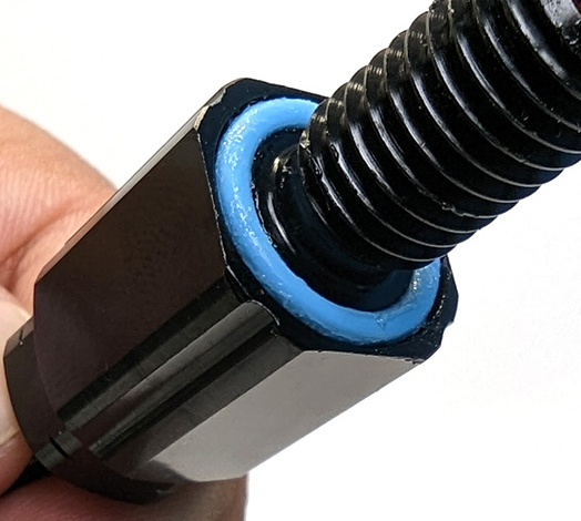
3. Check the installation port hole; the area around the hole should be clean and free of dust, dirt, hair, scratches, or debris.
4. Follow the steps for the type of hole you’re working with:
For unthreaded holes:
- Insert the bulkhead into the hole and secure it with the included nut on the opposite side.
- Tighten by hand until finger-tight, then use an M10 bulkhead wrench (or 16 mm wrench) to fully tighten.
- When properly installed, the bulkhead should not rotate, and you should not be able to loosen it by hand
For threaded holes:
- Thread the bulkhead directly into the hole until finger-tight.
- Do not use the included nut.
- Use an M10 bulkhead wrench (or 16 mm wrench) to fully tighten.
- When properly installed, the bulkhead should not rotate, and you should not be able to loosen it by hand.
Making an Installation Hole
You can also create your own hole to install the BarXT sensor. The mounting surface must be:
- Flat: so the O-ring can seat properly. A curved or uneven surface will not seal.
- Smooth: rough or textured surfaces will not seal.
When making a hole, you can choose either an unthreaded clearance hole or a threaded hole:
- Unthreaded Hole: Drill a hole 10.0–10.2 mm in diameter.
- Threaded Hole: Drill an 8.5 mm pilot hole, then tap it with an M10x1.5 thread tap.
Wire Connections
The BarXT sensors communicate via I²C, making them compatible with many devices. In the following sections, we’ll cover general wiring instructions and then walk through some specific connections for common devices: Arduino, Raspberry Pi, Navigator, and Pixhawk.
General Connections
The BarXT sensor wires terminate in a 4-position JST GH connector. The pinout is shown below.
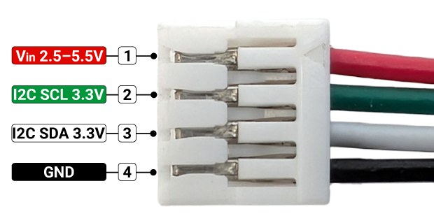
Connecting Power:
- Connect the red (Vin) wire to 2.5–5.5 V.
- Connect the black (GND) wire to ground.
Connecting SDA and SCL:
Connect the sensor to your device’s I²C bus:
- Connect the white SDA wire to the device’s SDA pin.
- Connect the green SCL wire to the device’s SCL pin.
These lines use 3.3 V logic:
- If your device also uses 3.3 V logic, you can connect the lines directly.
- If your device uses 5 V logic (like some Arduinos), you must use a logic level shifter to translate the data signals from one voltage to the other. ⚠️ Do not try to connect the sensor’s SDA and SCL lines directly to a 5 V device; this will damage the sensor.
Arduino Uno
The Arduino Uno (and many other Arduino boards) uses 5 V logic levels, so you’ll need a logic level converter to communicate with a 3.3 V device like the BarXT sensor.
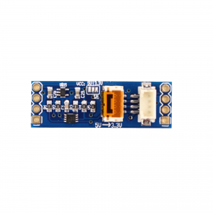
You’ll also need four male-to-female jumper wires.
1. Connect the BarXT sensor to the level converter using the JST GH connector on the 3.3V side.
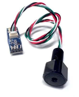
2. Connect the level converter pins on the 5V side to the Arduino using the jumper wires (the pin labels are on the back of the board):
- +5V → Arduino Uno 5 V power output
- SDA → Arduino Uno SDA pin (A4)
- SCL → Arduino Uno SCL pin (A5)
- GND → Arduino Uno GND pin
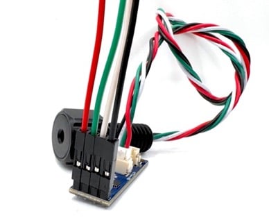
Jumper wire connections on the Level Converter board.
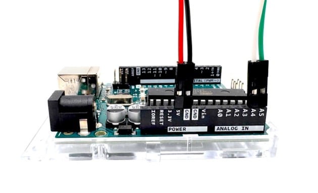
Jumper wire connections on an Arduino
Raspberry Pi
Raspberry Pi computers use 3.3 V logic, so the BarXT sensors can connect to it directly without a logic level converter. The Raspberry Pi GPIO header pinout is provided below, sourced from raspberrypi.com
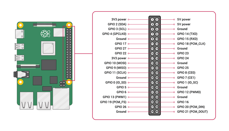
1. Connect the red Vin wire to the Raspberry Pi 3V3 or 5V power pin.
2. Connect the black GND wire to a Raspberry Pi ground pin.
3. Connect the white SDA wire to the Raspberry Pi SDA pin (board pin 3).
4. Connect the green SCL wire to the Raspberry Pi SCL pin (board pin 5).
Navigator Flight Controller
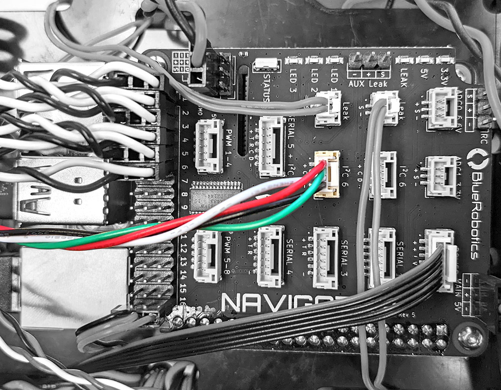
Connect the BarXT sensor to either one of the two I²C ports on the Navigator.
Pixhawk Autopilot
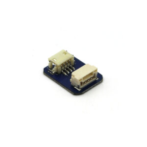
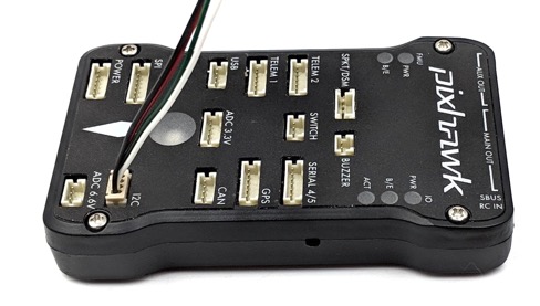
Most current Pixhawks use JST GH connectors, and the BarXT sensor can connect directly to the I²C port. Some older Pixhawk models use DF-13 connectors instead of JST GH. In this case, use the JST GH to DF13 Adapter to connect the sensor to the Pixhawk.
I²C Address
All BarXT models use I²C address 0x40. This address is hardcoded and cannot be changed, so only one BarXT sensor can be connected to a single I²C bus at a time.
If you need to use multiple BarXT sensors:
- Connect additional sensors to a different I²C bus, if one is available.
- Use a hardware I²C multiplexer.
Software Setup
To use this sensor in an ArduSub vehicle you will first need to enable the Keller driver. This section will show how to do so in BlueOs. We will then cover how to view the sensor readings in Cockpit or QGround Control.
ArduSub Vehicles
The BarXT sensors use the Keller LD pressure sensor driver. In ArduSub, this requires the Keller bit to be enabled in the BARO_PROBE_EXT parameter so the sensor can be detected correctly.
- Pixhawk-based systems require this bit to be enabled for the sensor to be detected.
- Navigator systems may detect the sensor without this parameter enabled, but confirming the setting ensures consistent behavior across platforms and future firmware updates.
To enable the Keller driver:
1. Open BlueOS and navigate to Autopilot Parameters.
2. Use the search bar to locate the BARO_PROBE_EXT parameter.
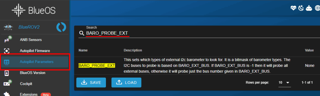
3. BARO_PROBE_EXT is presented as a list of driver options, making it easy to see which barometer drivers are enabled (multiple can be enabled at once). Enable Keller.
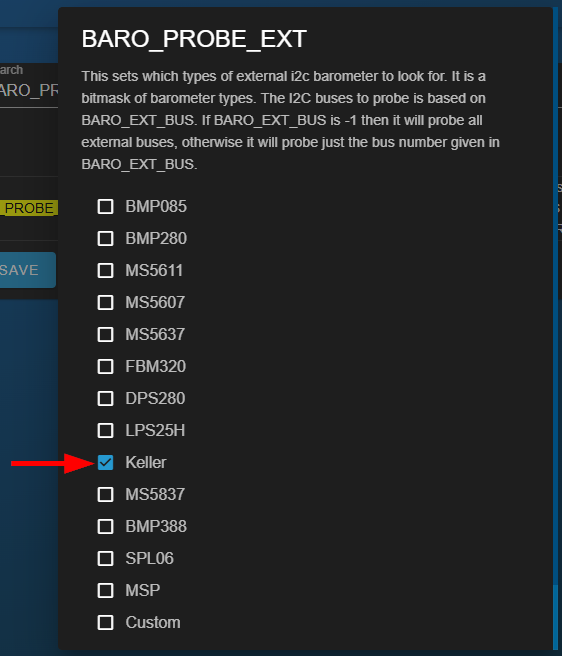
4. Apply changes and reboot if prompted.
View Depth in Cockpit
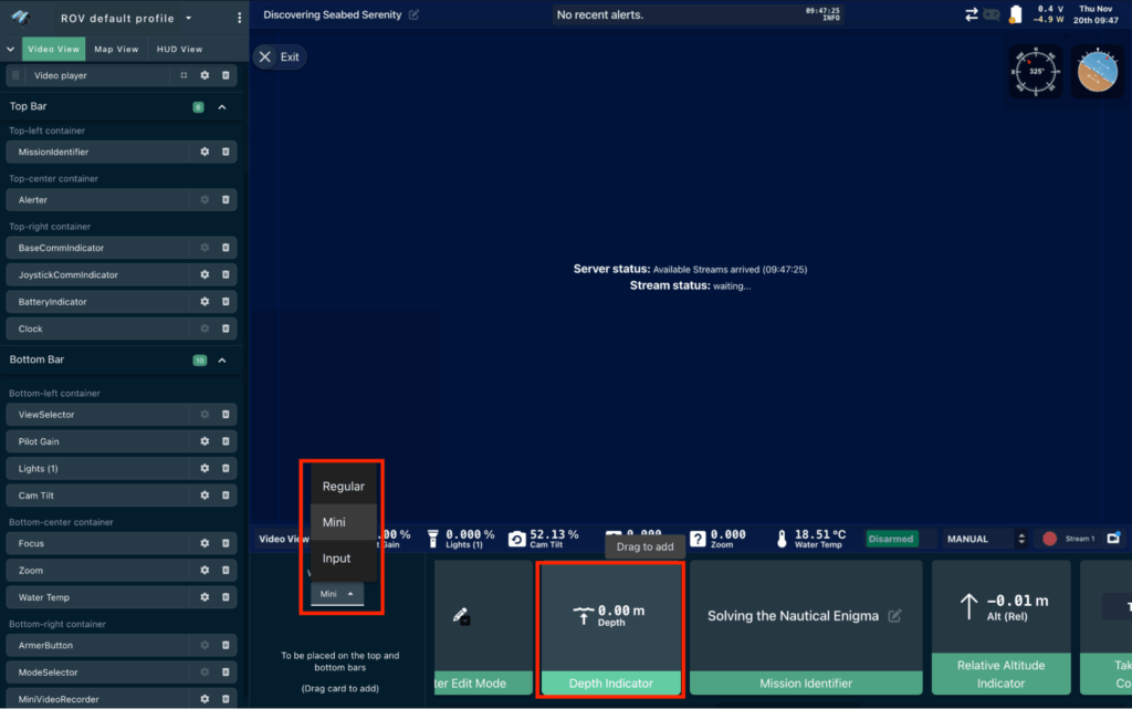
1. Open Cockpit. The depth value is usually displayed as a mini widget in the bottom bar.
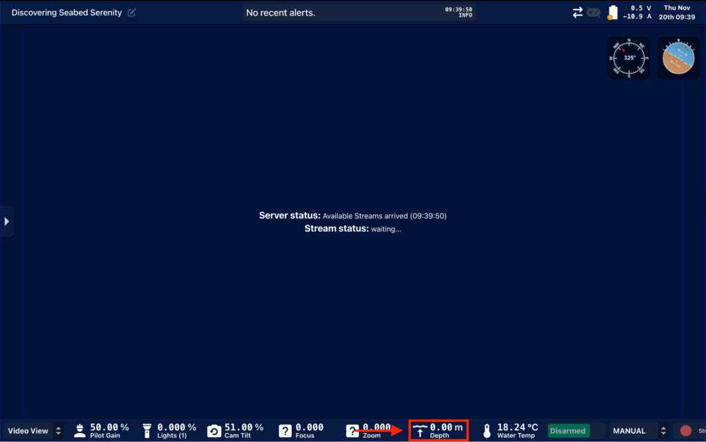
2. If depth is not displayed, expand the sidebar menu on the left side of the screen and choose Edit Interface.
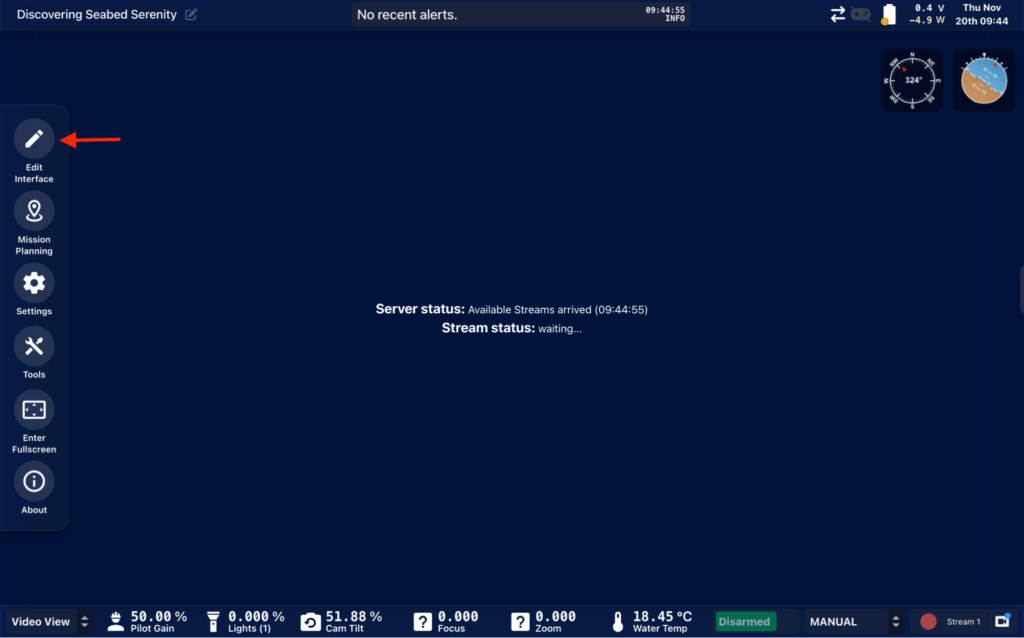
3. In the editing view, choose Mini for the widget type. Scroll through the mini widgets until you find Depth Indicator. Drag it onto the bottom bar to add it.
View Depth in QGroundControl
1. Open QGroundControl. The depth value is usually displayed in the Telemetry Panel.
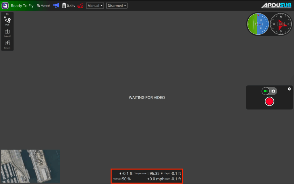
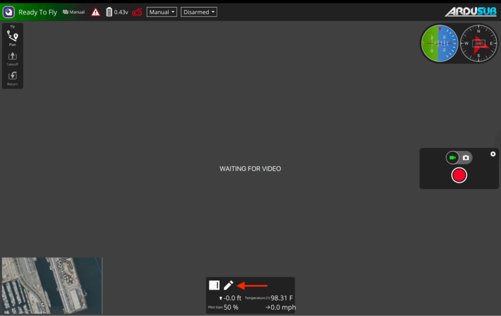
2. If the depth is not visible, hover over the Telemetry panel and select the pencil icon. Select an existing telemetry parameter to replace, or select the + button on the right or bottom of the panel to add a new row or column.
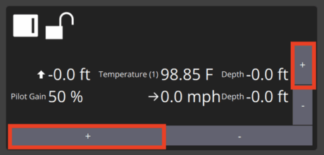
3. Select the parameter you want to change. A Value Display box appears, where you will select AltitudeRelative under the Vehicle category.
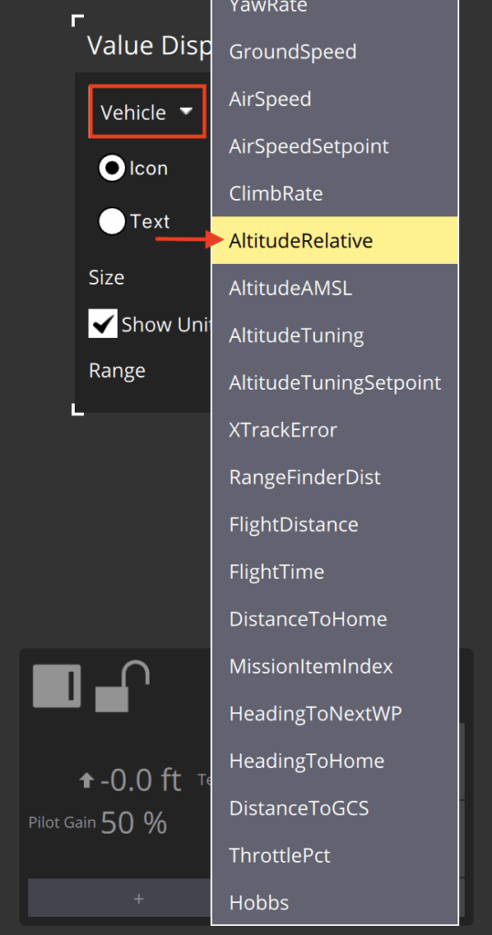
4. When finished, click Close, then click the padlock icon to lock your changes.
Code Examples
We have Keller libraries for both Arduino and Raspberry Pi / Python. This section will cover examples for each one.
Arduino
1. Install the BlueRobotics KellerLD Library:
- Open Library Manager in the Arduino IDE, search for “BlueRobotics KellerLD Arduino Library,” and click Install
- Or download the ZIP from GitHub, unzip it, and place the folder in your Arduino/libraries folder
2. Open an example sketch from the library or use this example:
#include <Wire.h>
#include "KellerLD.h"

KellerLD sensor;

void setup() {
  Serial.begin(9600);
  Wire.begin();
  sensor.init();
  sensor.setFluidDensity(997); // kg/m^3 (997 freshwater, 1029 for seawater)
  Serial.println("Starting");
}

void loop() {
  sensor.read();
  Serial.print("Pressure: ");
  Serial.print(sensor.pressure());
  Serial.println(" mbar");
  Serial.print("Temperature: ");
  Serial.print(sensor.temperature());
  Serial.println(" deg C");
  Serial.print("Depth: ");
  Serial.print(sensor.depth());
  Serial.println(" m");
  delay(1000);
}
3. Upload the sketch to the Arduino.
4. Open the Serial Monitor at 9600 baud to view live pressure, depth, and temperature readings.
Raspberry Pi / Python
This example uses the BlueRobotics KellerLD Python Library. Please check out the repository page for full instructions.
from kellerLD import KellerLD
import time

sensor = KellerLD()

if not sensor.init():
    print("Failed to initialize sensor")
    exit(1)

while True:
    try:
        sensor.read()
        print("Pressure: %.4f bar  Temperature: %.2f C  Depth: %.2f m" % (
            sensor.pressure(),
            sensor.temperature(),
            sensor.depth()
        ))
        time.sleep(0.2)
    except Exception as e:
        print(e)
Care and Maintenance
The BarXT sensors are designed for continuous submersion with no daily maintenance.
While no routine care is needed during deployment, we do recommend washing the sensor with fresh water after use in saltwater environments to reduce the effects of corrosion over time.
Troubleshooting
| Issue | Possible causes | Steps to troubleshoot |
|---|---|---|
| Sensor not recognized, no readings, or error reported in BlueOS, QGroundControl, or Cockpit | • The sensor is not being detected • Loose or damaged wiring • Faulty sensor or connector • Software not picking up the sensor | 1. Check the connection: Make sure the sensor is fully seated in the correct port on the Navigator and that the connector clicks in cleanly. 2. Inspect the cable: Make sure the sensor is fully seated in the correct port on the Navigator and that the connector clicks in cleanly. 3. Inspect the cable: Look for bent pins, corrosion, or any damage on the cable or housing. A bad pin will prevent the sensor from showing up. 4. Restart BlueOS and power cycle the system: Sometimes the sensor is not detected at boot. A full restart can bring it back. 5. Confirm software versions: Make sure BlueOS, ArduSub, QGroundControl and Cockpit are up to date. Older versions may not consistently detect newer hardware. 6. Test another port: Move the sensor to a different port. If it shows up on another port, the original port may have an issue. 7. Swap in another sensor if available: If a second sensor works and the original does not, that points to a faulty sensor or cable. 8. If nothing shows up on any port: At this point, the sensor is most likely bad, or the cable is damaged. Reach out to Support with photos and a description of what you have tested. |
| Initialization error or connection problem when used with a microcontroller | • SDA and SCL lines are swapped • Bad or inconsistent jumper wires • Wires are too long, causing a signal drop • Wrong logic level voltage • Logic level converter not powered correctly | 1. Check SDA and SCL wiring: Make sure SDA goes to SDA, and SCL goes to SCL. If you are unsure, swap them. It will not damage the sensor. 2. Test or replace jumper wires: Bad quality jumpers have terrible electrical connections. Check them for continuity, or swap in known-good ones. 3. Shorten the wiring: Long I2C runs can cause the sensor to fail initialization. Keep the wires as short as possible. 4. Confirm logic voltage: Use a 3.3V logic level converter for SDA and SCL connections. If it were connected directly to 5V, it may already be damaged. 5. Check the level converter: If you are using an I2C level shifter, make sure the 5V rail on the converter is actually powered. 6. Contact support if the issue persists: Reach out to Support with photos and a description of what you have tested. |
Help and Feedback
- If you need help using the BarXT sensor, reach out to our support team using our help center.
- We’re always working to make our guides, software, and user experience even better. If you have any ideas on how we can improve this guide, feel free to let us know here.