
Ping Sonar Repair Guide
Introduction
This guide is designed to help you confidently and easily navigate the Ping’s repair process. It provides step-by-step instructions for replacing the Ping’s PCB and cable. Let’s get right to it!
Taking the Ping Apart
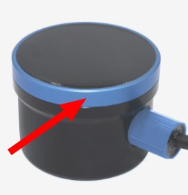
To open a first-generation Ping Sonar Altimeter and Echosounder, hold it firmly and turn the blue ring in a counterclockwise direction:
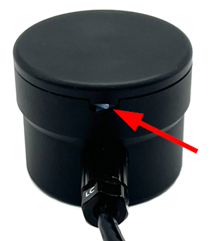
To open a second-generation Ping Sonar Altimeter and Echosounder, pull out the plastic locking cord, then carefully separate the top from the case. A gentle wiggle as you pull the halves apart can help separate the cap:
Disconnecting the Internals
You’ll need to disconnect some things first to replace the cable or PCB.
Tools You Will Need:
- Pliers or a small flathead screwdriver
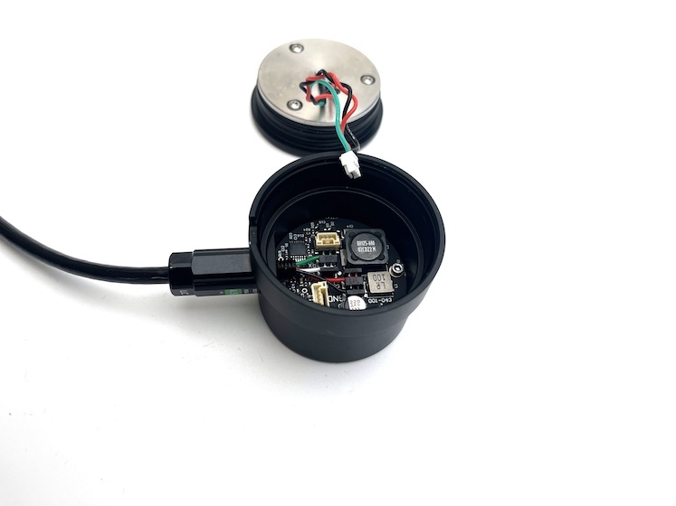
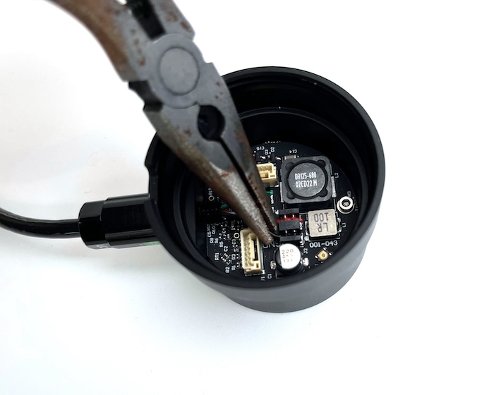
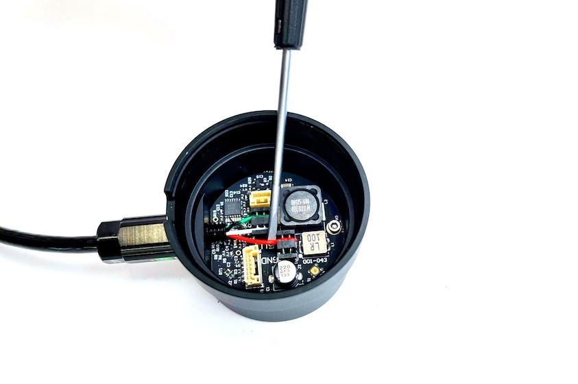
1. Disconnect the Ping head from the PCB. Press the lever on the JST-GH connector to detach it.
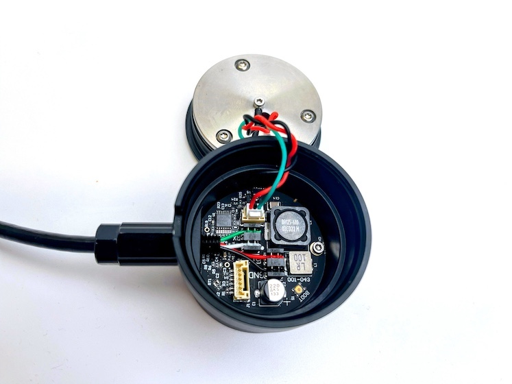
2. Carefully pry the green, white, red and black conductors from the IDC connector on the PCB using small pliers, or a small screwdriver. If you have a first-generation Ping you might have to remove a clear plastic film to access the wires. If possible, save the plastic and glue it back post repair. Its purpose is to keep the wires from getting twisted up when screwing the Ping head back on. It’s not essential but it is helpful to prevent damage.
Installing a New PCB
If the green LED does not turn on and you cannot connect to the device, the PCB needs to be replaced. This is a simple, straightforward process.
Parts and Tools You Will Need:
BR SKUs without a product page link can be ordered by adding this Special Request item to your cart, entering billing/shipping information, and specifying the item SKUs and quantities needed in the customer notes. At check out, Request a Quote. A sales representative will return the quote with the total cost and a payment link.
- 1.5 mm hex driver
- ESC: BR-100010
1. Unfasten the penetrator on the device side to remove the cable.
2. Unfasten the PCB screw to remove the damaged PCB.
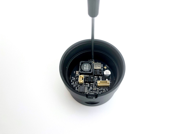
3. Fasten the replacement.
Cable Replacement
If your cable is damaged, needs to be lengthened, or if penetrators need to be replaced, follow these instructions .
Parts and Tools You Will Need:
- IDC (insulation-displacement contact) insertion tools:
- PUR Subsea Cable (it can be up to 8 m long)
- 11 mm WetLink Penetrator Plug Wrench
- M06 WetLink Bulkhead Wrench
- WetLink penetrators:
- M06-4.5MM-LC for the device side
- M10-4.5MM-LC for the cable end
- WetLink Penetrator Assembly Block
- Cable Jacket Stripper
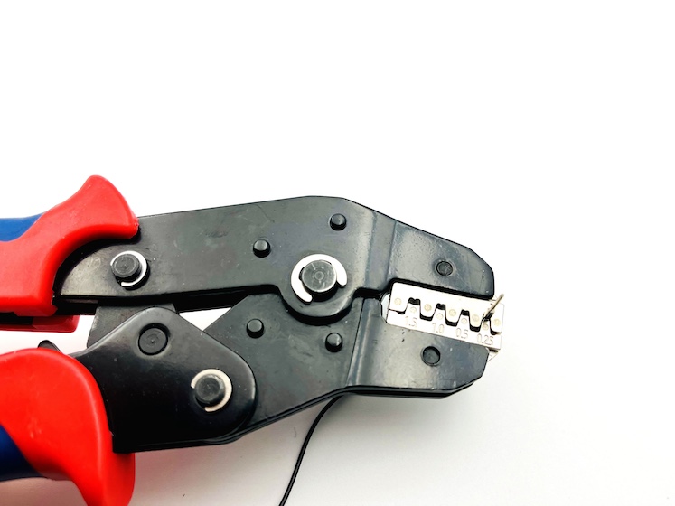
- AWG 18 to 28 crimp tool
- 10-22AWG wire strippers
- Wire cutters
- 4x crimp connector housings (if yours are damaged, otherwise the same one case be used)
- 4x male crimp pins
Device Side:
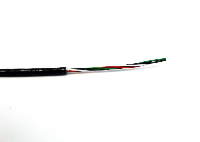
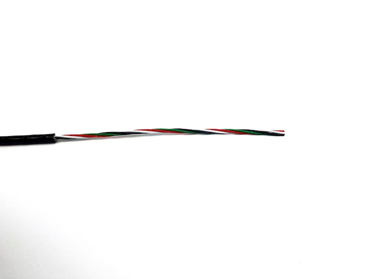
1. Strip 7 cm off the cable jacket and cut the fillers.
2. Follow the WetLink Penetrator Assembly Guide and install the WLP-M06-4.5MM-LC.
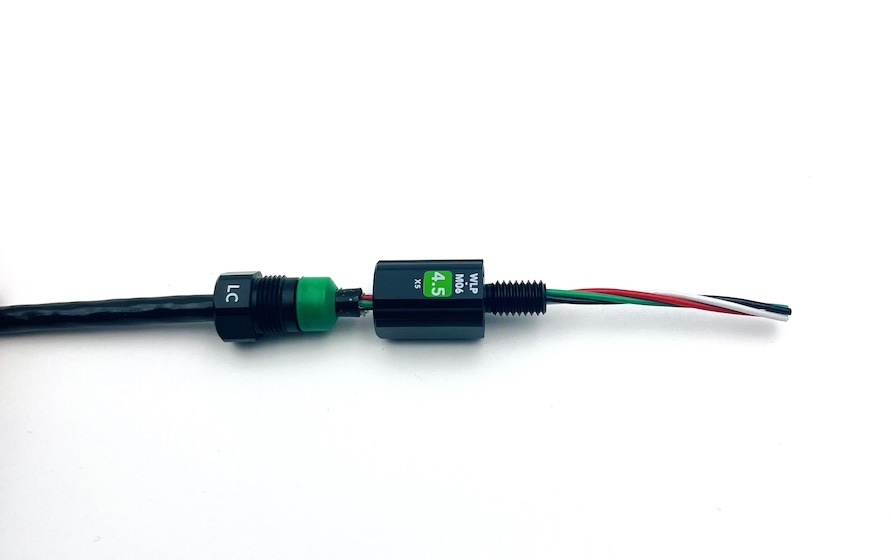
3. Fasten the WLP on the device side to the Ping body; don’t forget the greased O-ring.
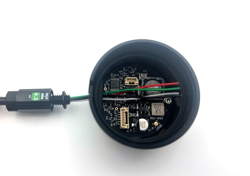
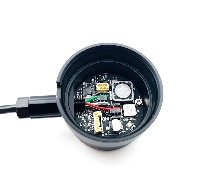
4. Punch in the black, red, white, green wires with the IDC punch hand tool to the corresponding labels on the PCB:
- GND – black
- 5V – red
- TX – white
- RX – green
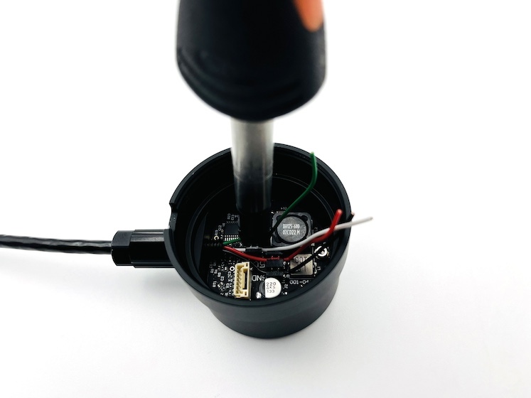
5. Clip the wires with wire cutters.
Cable end:
1. Strip 13 cm from the cable jacket and cut the fillers.
2. Follow the WetLink Penetrator Assembly Guide to install the M10-4.5MM-LC.
3. Strip 1mm off the four conductors.
4. Crimp the wires with male crimp pins.
5. Install the male pins in the crimp connector housings.
6. Reconnect the Ping head to the PCB.
7. Fasten the Ping head to the body. Install the locking cord if you are repairing a Ping2.
Troubleshooting
If the green LED on the PCB does not light upon powering the Ping, please contact the support team via the support form on the contact page.
What did you think of this guide? Can we improve it? Let us know here!