
Guide to the Thruster Commander

Introduction
The Thruster Commander makes it easy to get started with our thrusters and speed controllers. It comes with a control unit, potentiometers, knobs, cables, and terminal blocks to get thrusting quickly!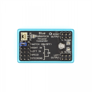
Why do I need the Thruster Commander?
Most ESCs do not accept simple knob- or button-inputs, instead communicating via pulse-width modulation (PWM) signals. The Thruster Commander converts up to two potentiometer (knob) inputs to two separate PWM output signals that can be used to control ESCs. This allows you to run BLDC motors without the need for a complex onboard computer system.Why can't I use the Thruster Commander with other ESCs?
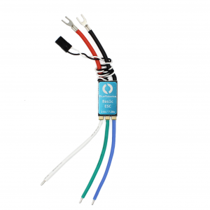
Most ESCs are designed for RC airplane or multi-copter use. Motors on these craft never need to be run in reverse, so most ESCs are uni-directional. However the Thruster Commander is designed to be used with bi-directional ESCs. Because of the different operating natures of uni-directional and bi-directional ESCs, the signals required to stop these types of ESCs are different, so the Thruster Commander’s safety features (which are meant to stop all attached motors) will not work with uni-directional ESCs. For this reason the Thruster Commander should never be used with uni-directional ESCs.It is possible to upload bi-directional firmware to some standard ESCs. More information can be found in the Basic ESC documentation.
Important Notes
Only use the Thruster Commander with reversible/bi-directional ESCs, like Blue Robotics ESCs. Standard ESCs are not compatible with the Thruster Commander’s safety features. See below for more information.
Neither the Thruster Commander nor its included accessories are waterproof. Make sure to mount them in locations where they will not get wet.
Deadman switches are recommended on any mobile Thruster Commander application.
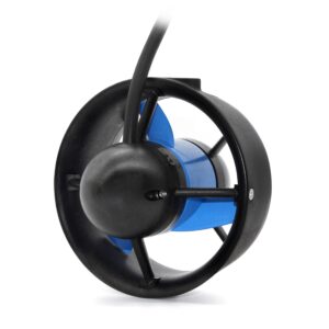
ESCs are necessary for powering brushless DC (BLDC) motors (e.g. T200 or T500 thrusters), even to run at full speed.
Most ESCs require a neutral input signal to complete their initialization. This is a safety feature! The Thruster Commander will output a neutral signal when:
- SWITCH is open (i.e. not connected to ground),
- input potentiometers are centered, or
- not enough potentiometers are connected.
Parts and Tools
You Will Need
Optional
You will also need: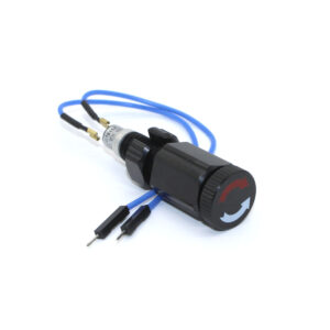
- 1 x #2 Phillips head screwdriver
Video Tutorial
Quick Start
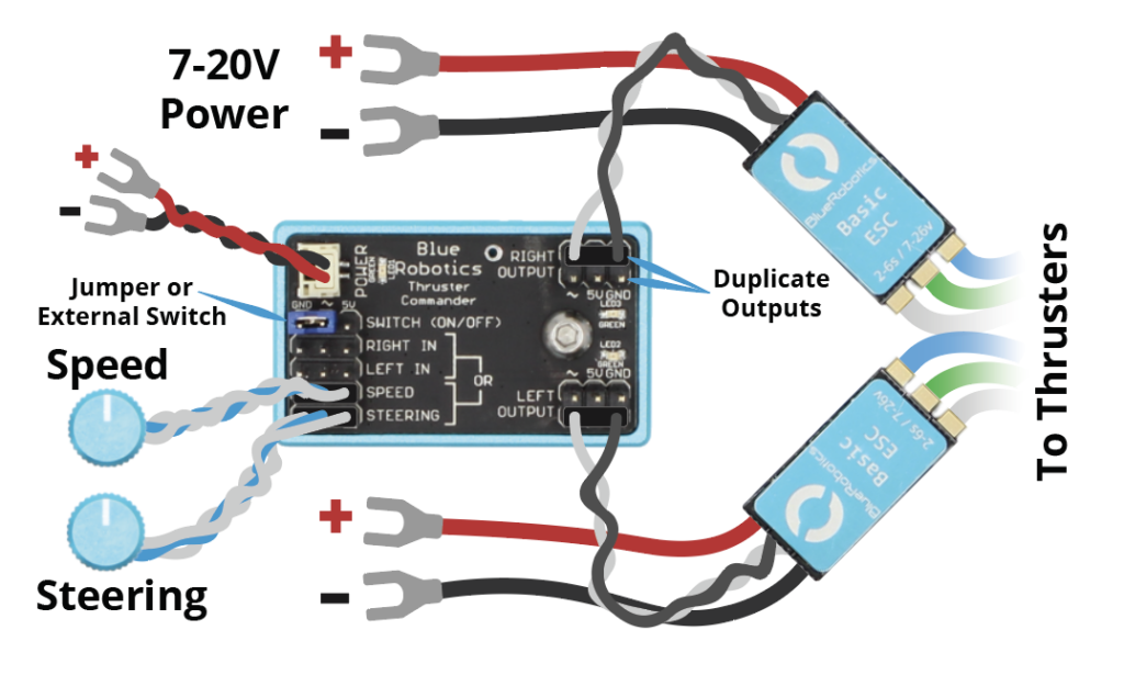
- Connect the power cable to the POWER connector in the top left of the board.
- Attach the potentiometer(s) to the inputs (see Modes of Operation for input configurations).
- Each potentiometer’s 3-pin connector can be reversed to reverse its input.
- Attach electronic speed controllers (ESCs) to the output pins.
- The black/brown wire should be connected to the GND pin.
- These connectors should not be reversed.
- Apply 7-20 VDC power to the POWER connector and ESCs.
- To initialize the ESCs, either:
- Turn the knobs to their center position, or
- Turn the external switch to the off position
- That’s it! You’re ready to go.
Modes of Operation
| Mode | Inputs | Outputs |
|---|---|---|
| Single Input | SPEED | SPEED Both OUTPUTs |
| Dual Input | RIGHT IN and LEFT IN | RIGHT IN RIGHT OUTPUT LEFT IN LEFT OUTPUT |
| Mixed Input | SPEED and STEERING | SPEED and STEERING Both OUTPUTs |
Powering Thruster Commander
The Thruster Commander can be powered in one of two ways: 7-20 VDC or regulated 5 VDC. 7-20 VDC power can be supplied via the POWER connector in the top left corner of the board. This can be connected directly to any 7-20 VDC power supply, including the batteries powering your motors.
Make sure you do not power the Thruster Commander with greater than 20 VDC. If you are using a higher voltage to power your ESC and thruster (for example, using a 6S battery to power the T500), you must use a separate power supply for the Thruster Commander. The 5V 6A Power Supply can be used for this.
Note that not all ESCs with such three-wire PWM input cables have built-in BECs.
Connecting the Battery and ESCs
A 6-pole barrier block and jumpers are provided for connecting power between the Thruster Commander, ESCs, and the provided XT90 connector/your power source of choice. The six poles of the barrier block can be connected as shown into two sets of three with the provided jumpers; one set for power (red) and one for ground (black).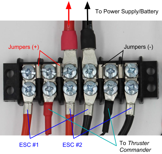 |
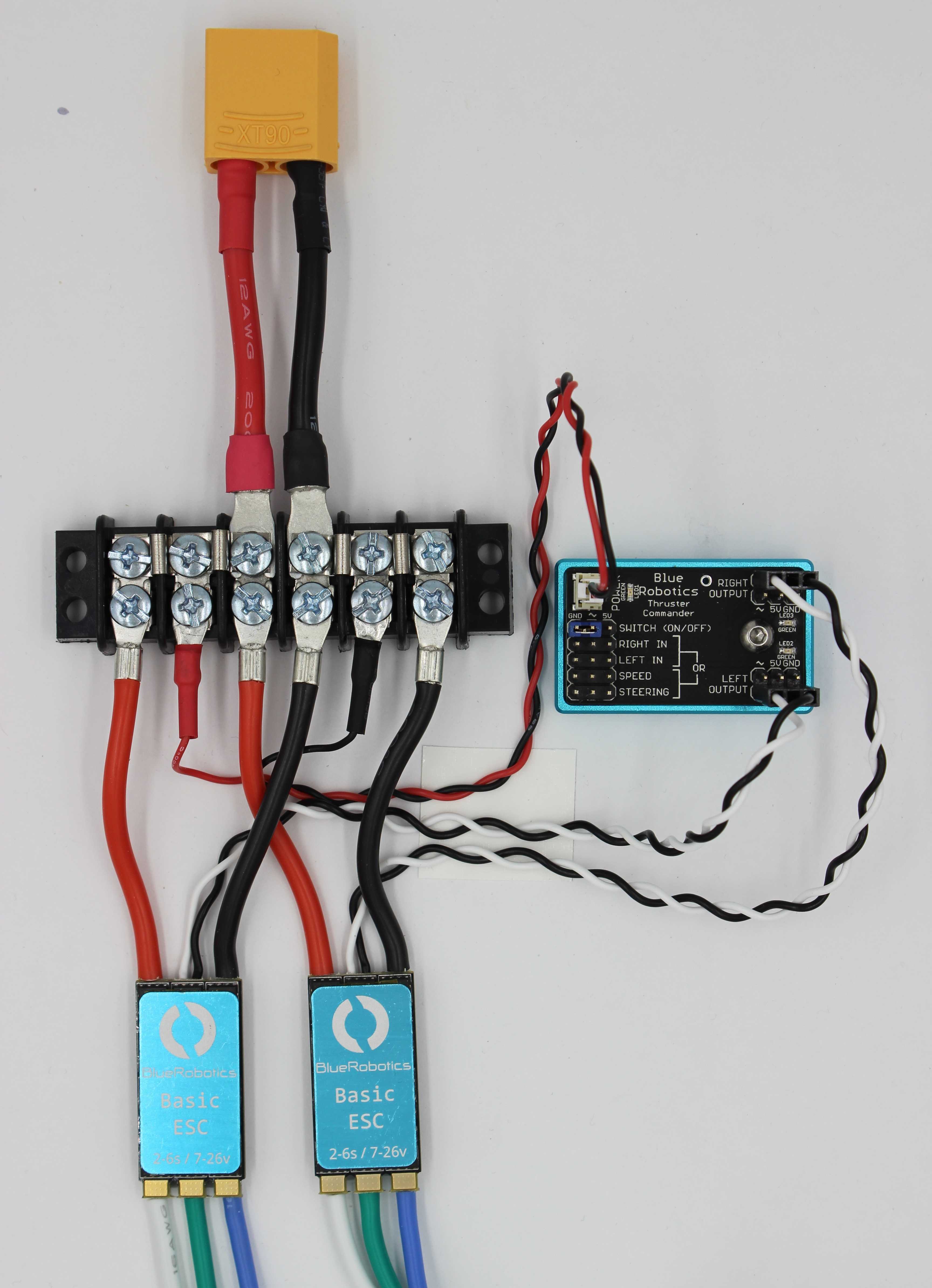 |
The Thruster Commander, ESCs, and batteries do not contain reverse-polarity or short-circuit protections. Double-check your wiring before applying power for the first time.
Mounting Thruster Commander
Two M3x0.5 holes spaced 31.75 mm (1.25″) apart on the back of each Thruster Commander provide a solid way to mount it on your project. Alternatively the Thruster Commander can be mounted with double-sided tape. However you mount the Thruster Commander, make sure it is in a location where it will stay dry, because the Thruster Commander and its accessories are not waterproof. The potentiometers can be mounted through a 10 mm (3/8″) hole in a panel or box up to 2.5 mm (0.1″) thick. After removing the nut and washer from the potentiometer, pass the potentiometer through the mounting hole from the back of the panel or box. Replace and tighten the nut and washer, then attach the knobs to the potentiometer by tightening the set screw onto the flat section of the potentiometer shaft using the provided 1.5 mm allen wrench.Deadman Switch/Enabling Output
To enable PWM outputs from Thruster Commander, the center SWITCH pin must be connected to ground, indicated on the board as “GND”. This is achieved out-of-the-box with a jumper between the center and GND pins of SWITCH. A deadman switch can be added by replacing this jumper with any normally-open (NO) momentary switch connected between the center pin and GND. External “enable” switches can also be used. Should the switch be released or become disconnected from Thruster Commander, the SWITCH-to-GND connection will be broken and Thruster Commander will stop all connected motors.
If you are using the Thruster Commander on a vehicle, we highly recommend that you install a deadman switch to prevent it from running off without you.
Modifying or Replacing Potentiometers
The potentiometers included with the Thruster Commander are standard 10 kΩ potentiometers with center detents. These can be replaced with any potentiometers with a resistance of 10 kΩ or less. We recommend those with center detents to make it easier to set the motors to neutral. To fit the knobs, replacement potentiometers should have 6 mm diameter shafts with flats for a set screw. Should different-length cables for the potentiometers be necessary, the wires may be lengthened or shortened as desired. However they should not be run directly alongside wires carrying power for motors, as they may interfere with the potentiometers’ analog outputs (i.e. sharing a tether).Operation
ESC Initialization
Most BLDC ESCs have a built-in safety feature that requires a neutral input signal (1500 µs) before they will complete their initialization. While this reduces the chances of a thruster unexpectedly turning on and lacerating you or your friends, it necessitates an extra initialization step at runtime. The Thruster Commander outputs a neutral PWM signal to connected ESCs when:- SWITCH is open (i.e. not connected to ground),
- input potentiometers are centered, or
- not enough potentiometers are connected.
Controlling Motors
Each Thruster Commander contains two output channels (LEFT OUTPUT and RIGHT OUTPUT) with two sets of output pins each. This means that the Thruster Commander can control two sets of motors independently. Three modes of operation are supported: Single Input, Dual Input, and Mixed Input. The mode is selected by connecting potentiometers to specific inputs. See Modes of Operation for valid combinations of potentiometer connections.- Single Input uses a single potentiometer connected to the SPEED input to drive both the RIGHT and LEFT OUTPUTs identically.
- Dual Input uses two potentiometer inputs, one on RIGHT IN and one on LEFT IN. The input on RIGHT IN will dictate the output on RIGHT OUTPUT and the input on LEFT IN will dictate the output on LEFT OUTPUT.
- Mixed Input is designed for use with crafts with left and right thrusters for differential thrust steering. In these setups, SPEED controls the base speed of the craft and STEERING controls the differential thrust.
Potentiometers can be hot-swapped. However it is advised that this only be done while the outputs are disabled (SWITCH disconnected from GND or power to thrusters disconnected), as hot-swapping potentiometers while the outputs are enabled may cause one or more motors to suddenly start running.
Troubleshooting
| Two short blinks | |
|---|---|
 |
Not enough potentiometers are plugged in. The Modes of Operation table shows all valid combinations of potentiometer connections. |
| One long blink | |
|---|---|
 |
Switch is not pressed/connected, or is not correctly connected. The SWITCH signal (center) pin must be connected to ground (GND pin) by a switch or jumper for the motors to turn. |