
Subsea RGB LED Indicator Guide
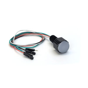
The Subsea RGB LED Indicator is a great way to add a status light to underwater enclosures or other hardware. It uses a WS2812B LED and is compatible with most existing WS2812B software libraries. This guide will show you how to install and use the Subsea RGB LED Indicator.
Installing the Indicator
The Indicator uses the M10 bulkhead penetrator form factor, and can be installed in any M10-size hole in a Blue Robotics Watertight Enclosure or Watertight Box.
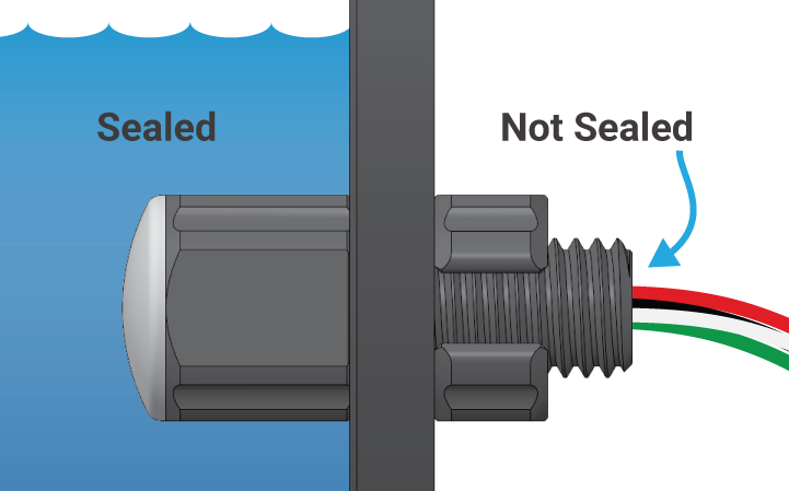
Indicator installed through an enclosure.
Installation Procedure
1. Inspect the included O-ring—it should be clean and free of dents, cuts, or damage.
2. Apply a thin layer of silicone grease (such as Molykote 111) to the O-ring and place it in the groove on the underside of the bulkhead.
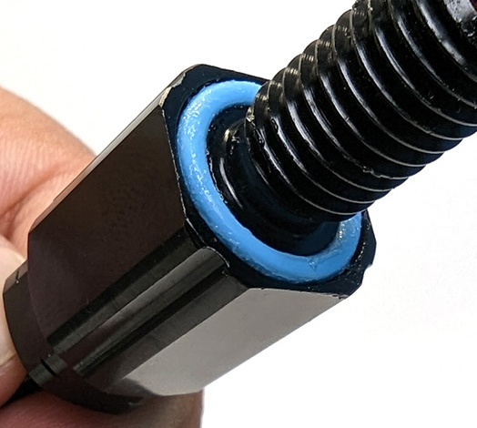
3. Check the installation port hole—the area around the hole should be clean and free of dust, dirt, hair, scratches, or debris.
4. Follow the steps for the type of hole you’re working with:
For unthreaded holes:
- Insert the bulkhead into the hole and secure it with the included nut on the opposite side.
- Tighten by hand until finger-tight, then use an M10 bulkhead wrench (or 16 mm wrench) to fully tighten.
- When properly installed, the bulkhead should not rotate, and you should not be able to loosen it by hand.
For threaded holes:
- Thread the bulkhead directly into the hole until finger-tight.
- Do not use the included nut.
- Use an M10 bulkhead wrench (or 16 mm wrench) to fully tighten.
- When properly installed, the bulkhead should not rotate, and you should not be able to loosen it by hand.
Making an Installation Hole
You can also create your own hole to install the Indicator in your own hardware. The mounting surface must be:
- Flat: so the O-ring can seat properly. A curved or uneven surface will not seal.
- Smooth: rough or textured surfaces will not seal.
When making a hole, you can choose either an unthreaded clearance hole or a threaded hole:
- Unthreaded Hole: Drill a hole 10.0–10.2 mm in diameter.
- Threaded Hole: Drill an 8.5 mm pilot hole, then tap it with an M10x1.5 thread tap.
Wire Connections
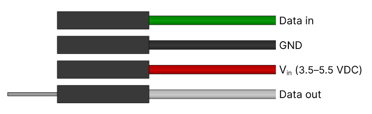
The Indicator wires terminate in 0.1″ (2.54 mm) header pins, making them compatible with most microcontroller pins and jumper wires. The pinout is shown below.
Power wires:
- Connect the red Vin wire to 3.5–5.5 VDC
- Connect the black GND wire to ground
- The Indicator should share a common ground reference with the serial data source
Data in:
- Connect the green (Data in) wire to the microcontroller serial data output
- The Data in voltage should be within ±0.5 V of Vin
Data out:
- The white Data out wire is used to daisy-chain Indicators. This allows you to control multiple Indicators from a single serial output pin
- Connect the Data out wire to the green Data in wire of the next Indicator in the series to daisy-chain
- If not using the Data out wire, use the included heat shrink to cover the exposed header pin
Using with a Navigator Flight Controller
The RGB Indicator can be connected to the RGB LED header on the Navigator flight controller.
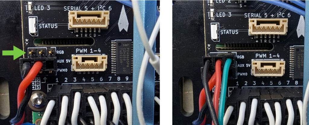
- Connect the black GND wire to the
-pin - Connect the red Vin wire the
+pin - Connect the green Data in wire to the
Dpin
+ pin of the AUX Leak or RC header if that is more convenient.
When using the Navigator with an ArduPilot vehicle firmware, the RGB connector will default to displaying the autopilot’s status.
- The Navigator’s built in status LED shares its signal wire with the RGB header, but uses a GRB ordering, so the colours will not match – the red and green signals are swapped. The firmware does not yet allow selecting whether the onboard LED or the RGB Indicator shows the status correctly.
- For custom control over the LED Indicator, set the
NTF_LED_OVERRIDEparameter to 1. This allows external control via LED_CONTROL MAVLink messages, or onboard control via a Lua script running on the autopilot.
Code Libraries
The Indicator is compatible with most WS2812B software libraries. We’ve tested the following libraries:
Arduino Uno Example
This example code uses the Adafruit NeoPixel library to control one Indicator. It changes the LED color to red, green, blue, then runs through a rainbow cycle. You will need three male-to-male jumper wires to connect the Indicator wires to the Arduino Uno pins.
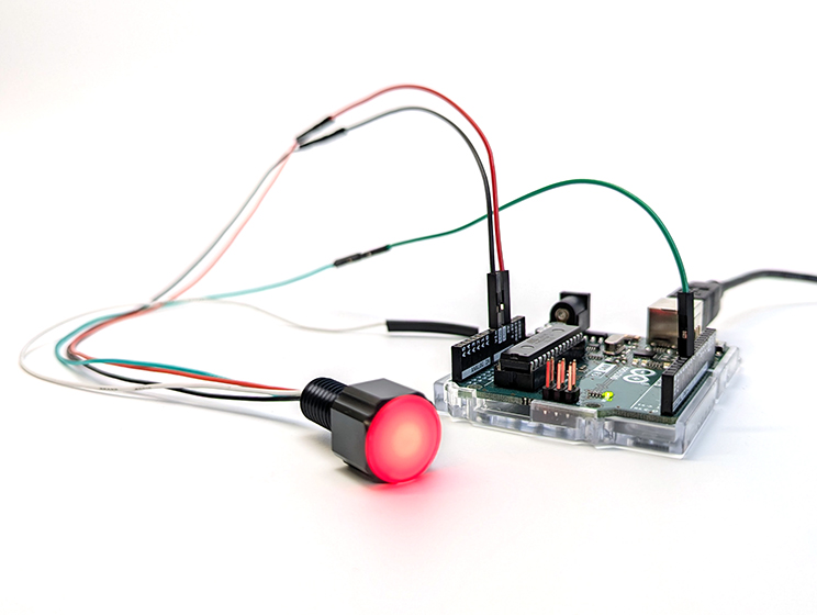
1. Use the jumper wires to make the following connections:
- red wire to the 5V pin
- black wire to a GND pin
- green wire to pin 6
The white wire isn’t used in this example, you can cover it using the included heat shrink.
2. Connect the Arduino to your computer.
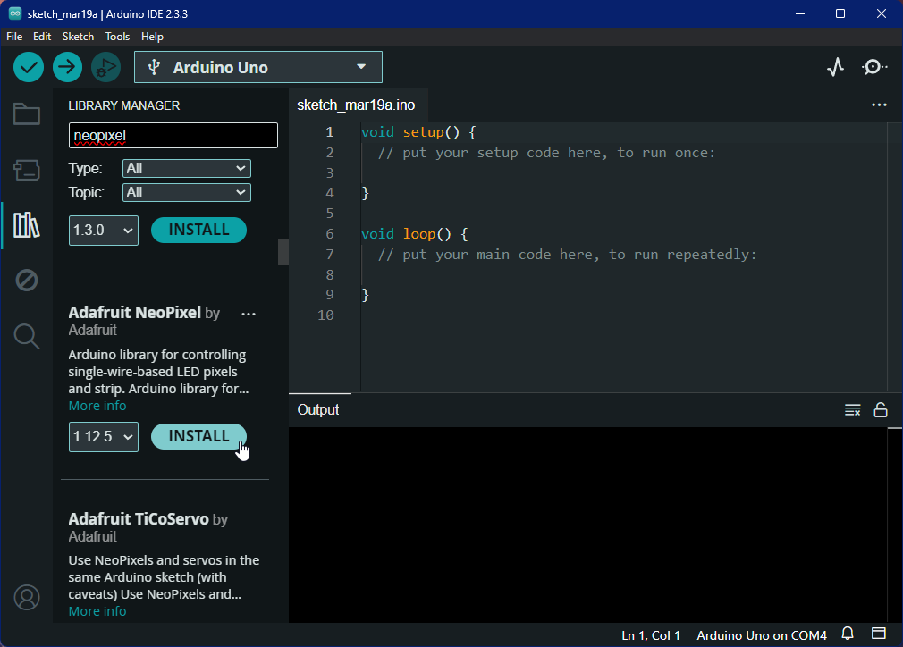
3. Open the Arduino IDE Library Manager, search for “neopixel”, and install the Adafruit NeoPixel library.
4. Download the following file and extract the sketch folder. Open the sketch in the Arduino IDE or copy and paste its contents in a new sketch.
- RGB-INDICATOR-TEST (zip)
5. Upload the sketch to the Arduino, the Indicator should begin changing colors.
Feedback
We’re always working to make our guides, software, and user experience even better. If you have any ideas on how we can improve this guide, feel free to let us know here.