
M200 and M500 Motor User Guide
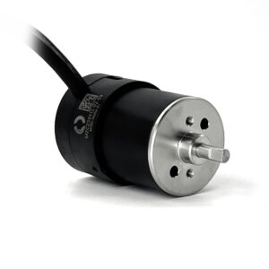
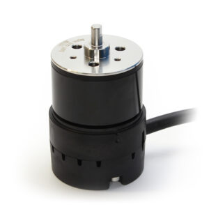
The M200 and M500 are subsea motors designed to run in harsh ocean conditions, making them perfect for use on USVs (like the BlueBoat), AUVs, and in custom projects such as actuators and subsea tooling. This guide explains how to use and service the M200 and M500.
Important Safety Notes
Parts of a Motor
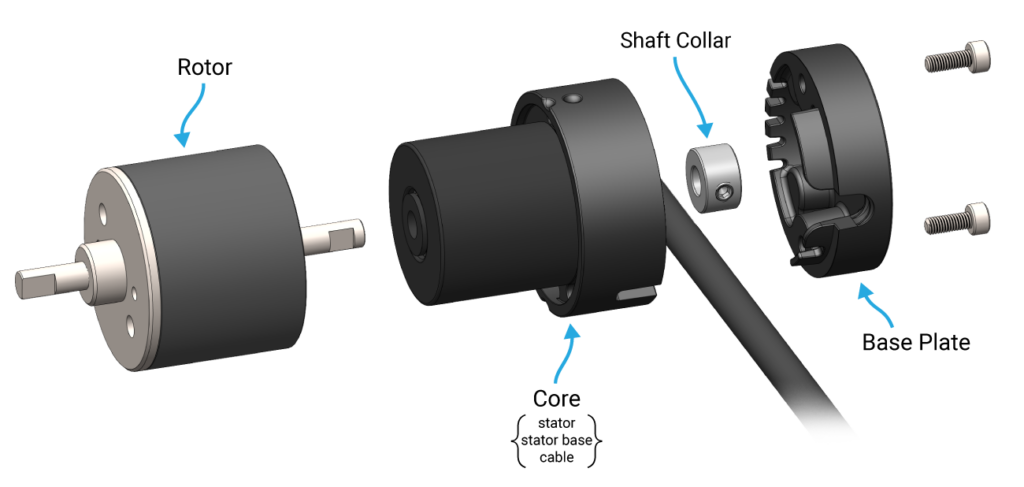
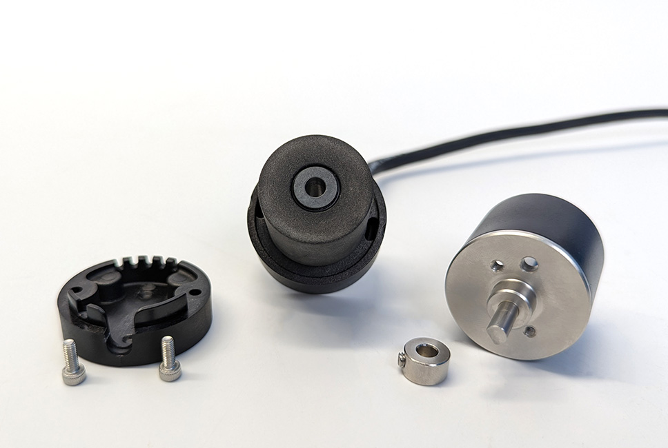
The M200 and M500 are outrunner motors. This means the entire outer rotor spins while the inner stator remains stationary. The following diagram shows the components of the motors.
Rotor Attachments
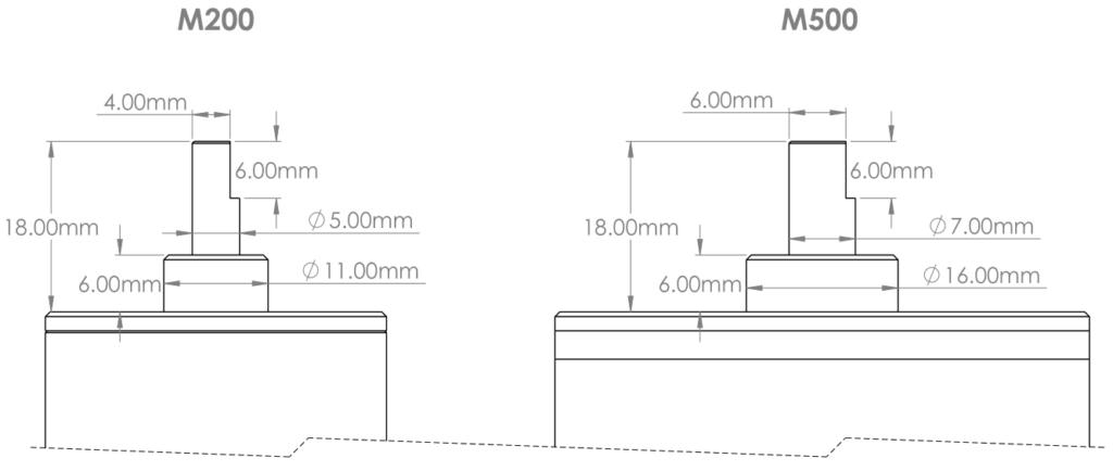
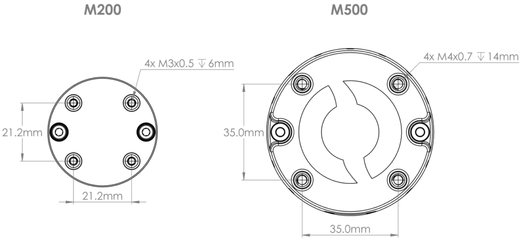
The top of the rotor has threaded holes that can be used to attach propellers, tools, or other driven components. The two larger unthreaded holes are vents for drainage. Refer to the diagrams below for thread sizes, hole patterns, and maximum screw engagement depths for each motor.
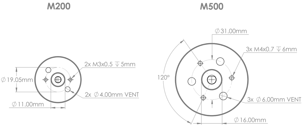
The rotor shaft has a drive flat—a flat section milled into the shaft that provides a positive surface for a fastener to bear against, preventing an attached component from slipping during operation.
Operating the Motor
To operate a motor you need:
- The motor
- A brushless electronic speed controller (ESC) – always required, even if you don’t need variable speed or direction control. Unlike brushed motors, brushless motors need an ESC to energize the motor phases at the correct timing.
- A power source – a battery or power supply within the operating voltage range of your motor.
- A signal to control the ESC – any device that can output a PWM signal, such as a microcontroller, RC receiver, or the Thruster Commander. The signal tells the ESC how fast and in which direction to run the motor.
The following diagram shows how everything is connected:
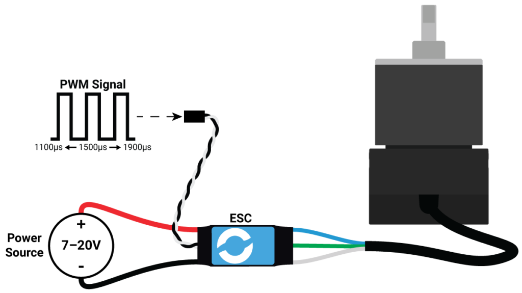
The following instructions cover operation with a Blue Robotics ESC. If you’re using a third-party ESC, the wiring is the same but refer to your ESC’s documentation for initialization and signal details.
Connecting to an ESC
The motor cable has three conductors that terminate in tinned wire ends.
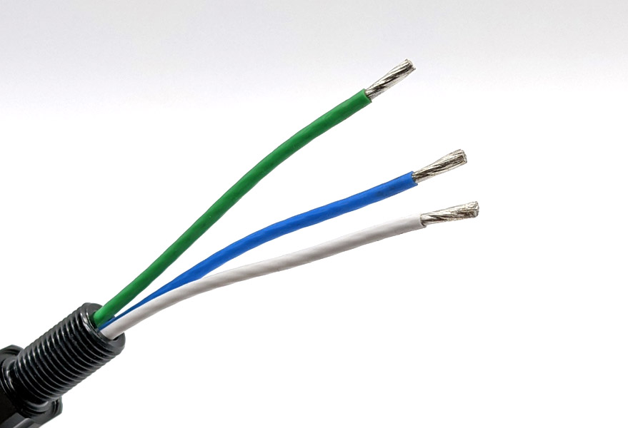
Connect these to the three motor phase wires on your ESC. The wires can be soldered together or connected using bullet connectors or screw terminal blocks. The order does not matter—the motor will spin regardless of how the three wires are connected. If the motor spins in the wrong direction, swap any two of the three wires.
Connecting to a Power Source
Connect the red (positive) and black (ground) ESC power wires to your power source. Make sure the voltage is within the operating range for your motor:
M200: 7–20V
M500: 7–24V
When the ESC is connected to power you should hear three beeps in rising pitch indicating the ESC is on and ready.
Sending a Signal
Connect the white ESC signal wire to your signal source, and the black (ground) ESC wire to a ground pin on the signal source. Send a PWM signal of 1500 µs to initialize the ESC. When initialized you will hear two more beeps—the first confirms a throttle signal is detected, the second confirms the correct 1500 µs signal and that the ESC is fully initialized.
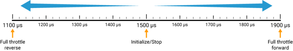
Once initialized, the motor speed and direction is controlled by varying the PWM signal:
- 1500 µs to stop
- 1525–1900 µs for forward
- 1475–1100 µs for reverse
Signal Sources
Almost any device that can output a PWM signal can be used to control the motor. The ESC expects a pulse-width signal measured in microseconds (µs), not a duty cycle percentage, so make sure your signal source supports this format.
Here are some common options:
Blue Robotics Thruster Commander
The simplest way to get started. The Thruster Commander is a standalone controller designed specifically for Blue Robotics thrusters and motors, and requires no programming or setup. We recommend it for first-time users.
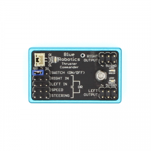

Guide to the Thruster Commander
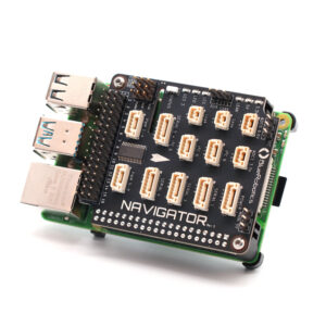
Flight Controllers (Navigator, Pixhawk, etc.)
The best choice for unmanned vehicles like ROVs, AUVs, and USVs. Flight controllers handle motor control as part of a larger system, managing navigation, stabilization, and autonomy.
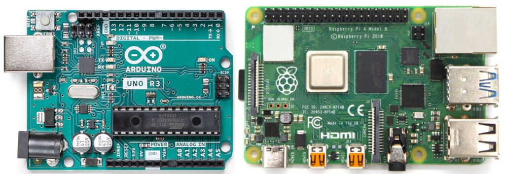
Microcontrollers and SBCs (Arduino, Raspberry Pi, etc.)
A flexible option for custom projects. Microcontrollers can be programmed to control the motor in just about any way you can imagine, from simple manual control to fully autonomous operation.
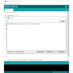
Control the Basic ESC with the Arduino Serial Monitor
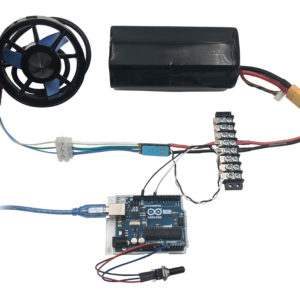
Control the Basic ESC with a Potentiometer and Arduino
RC Transmitters and Receivers
A good option for simple wireless control of surface vehicles. Keep in mind RC signals don’t work underwater!
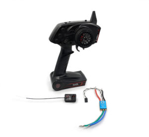
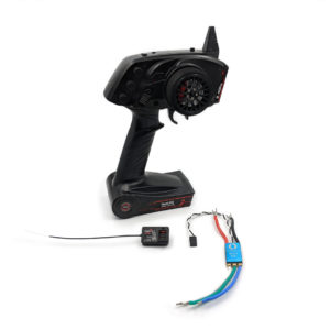
Control the Basic ESC with an RC Transmitter
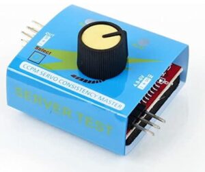
Simple Servo testers
The simplest possible signal source,useful for bench testing or as a single-input manual controller.
Motor Mounting
The motor can be mounted in two ways depending on your application.
Base Plate Mounting
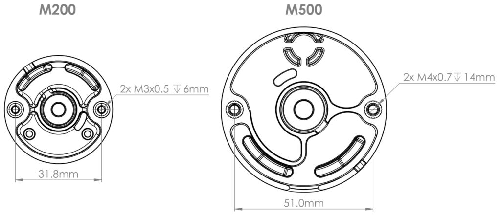
The motor can be mounted using the four threaded inserts on the base plate. This is the recommended mounting method as the base plate provides cable strain relief. Refer to the diagram below for the mounting hole pattern and thread specifications.
Stator Base Mounting
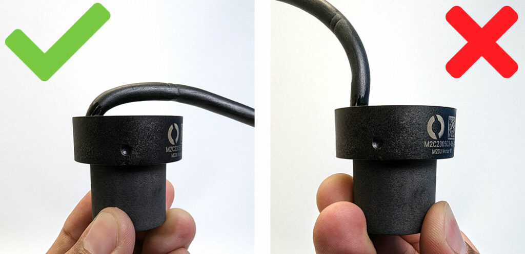
The base plate can be removed and the motor mounted directly from the threaded inserts on the stator base. This method exposes the cable epoxy joint, so make sure to provide external cable strain relief and maintain the natural cable bend direction. Bending or straining the cable in the wrong direction can compromise the depth rating of the motor.
Tools
Refer to the table below for screw and tool sizes.
| Component | M200 | M500 |
|---|---|---|
| Base plate screws [drive] | M3x8 mm socket head cap [2.5 mm hex] | M4x22 mm socket head cap [3 mm hex] |
| Shaft collar set screw [drive] | M4x4 mm set screw [2.0 mm hex] | M5x5 mm set screw [2.5 mm hex] |
Motor Disassembly and Reassembly
You may need to disassemble the motor occasionally for cleaning and maintenance.
Disassembly
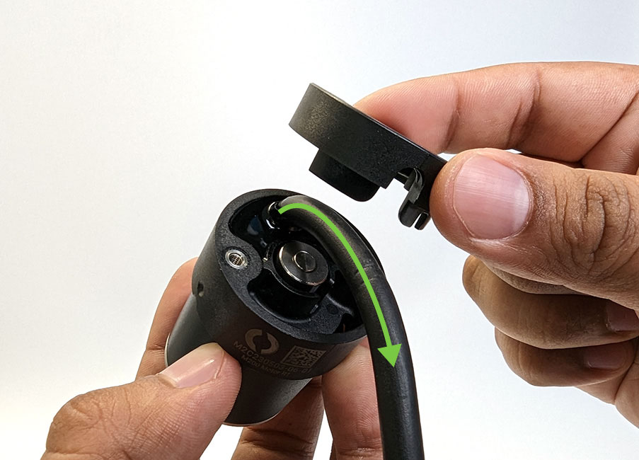
1. Remove the base plate screws and lift off the base plate.
Take note of the natural cable bend direction before removing — you will need to maintain this when reassembling.
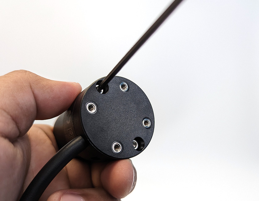
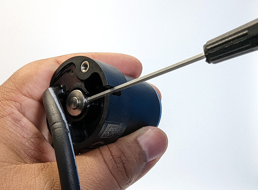
2. Rotate the rotor by hand until the shaft collar set screw lines up with the notch in the stator base. Use a hex driver to loosen the set screw.
3. Pull the rotor straight away from the motor core to separate it from the stator. Do not pry up on the shaft collar.
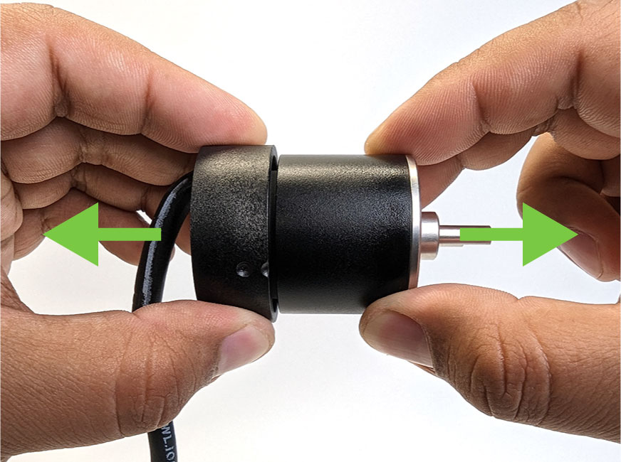
The motor is now disassembled.
Reassembly
1. Ensure the shaft collar is seated in the stator base, then install the rotor onto the motor core.
2. Tighten the shaft collar set screw onto the flat side of the rotor shaft.
3. Install the base plate, making sure to maintain the natural cable bend direction.
Care and Maintenance
After Every Use
- Rinse with fresh water after use in saltwater to minimize the accumulation of salt deposits.
- Rinse with fresh water after use in sandy or sediment-heavy environments.
Periodically
- Inspect the inside of the rotors and remove any buildup.
- Inspect the cable jacket for tears or damage.
Troubleshooting
ESC Beeps
When a motor is connected to an ESC, the ESC can use it as a “speaker” to play a series of beeps. These beeps provide information about the status of the ESC and are useful for troubleshooting. The following is the meaning of the beeps played during the typical initialization sequence.
1. At power on the ESC will beep three times in rising pitch. If you do not hear these beeps:
- The ESC may not be receiving power. Check your power supply and all power connections.
- The thruster may not be connected correctly to the ESC. Check that there is a good connection between the three ESC wires and the motor wires.
- The ESC may be defective.
2. If any throttle signal is detected the ESC will then beep one time. If you do not hear this beep:
- It means the ESC is not receiving any sort of throttle signal. Check the signal source to see if it is powered on and sending the correct signal.
- Check the connection between the signal source and the white ESC signal wire.
3. If the initialize/stop signal (1500 µs) is detected the ESC will beep one final time indicating that it is fully initialized. If you do not hear this beep:
- It means the ESC is not receiving the correct 1500 µs signal. Check if your signal source is sending the correct 1500 µs signal.
The motor does not spin or move at all
- This is usually an issue with the improper operation of the ESC. Refer to the ESC Beeps section above to troubleshoot the ESC.
The rotor tries to move but does not spin correctly
- All three motor wires may not be connected to the ESC wires correctly. Check that there is a good connection between the three ESC wires and the motor wires.
- There may be a broken motor wire or a short between wires. Check the resistance of each motor wire pair (blue wire/green wire, blue wire/white wire, green wire/white wire) using a multimeter. Each wire pair should have the same resistance within 0.1-0.2ohms or so. If there is no continuity between a pair, or one pair has significantly higher resistance, the thruster is defective.
- Try to rotate the rotor by hand, it should spin freely. If it is difficult to rotate, disassemble the motor and check for damage or blockage.
The rotor is jammed and cannot be turned by hand
- This can be caused by something jamming the rotor or by major internal damage caused by overheating, short circuits, heavily worn bearings, etc. Completely disassemble the motor and inspect for damage or blockage.
Swap-Components Troubleshooting
A great way to troubleshoot a problem is to swap components with other known-working components and observe whether the problem stays in place or moves with the component. To troubleshoot a motor using this method you will need an different motor and ESC set that you have confirmed is working normally.
1. Swap the problematic motor with a motor that you know works well. That is, connect the problematic motor to the ESC that was connected to the working motor and connect the working motor to the ESC that was connected to the problematic motor. If the problem follows the motor, you know that the motor is defective. If the problem stays with the ESC, move on to the next step.
2. Swap the signal sources of the ESCs. If the problem follows the problematic ESC, you know the ESC is defective. If the problem stays with the signal source, then there is a problem with the signal source.
Feedback
We’re always trying to make our documentation, instructions, software, and user experience better. If you’d like to leave feedback about how we can make this guide better, let us know here.