
Making an M200 Powered Brush
By Tony White
Introduction
Welcome back M200 Motor, we’ve missed you! This guide details how the M200 Motor can be adapted for applications outside of propulsion. While the torque specification for the M200 is the same as the T200 Thruster, its design is better suited for use in a gearbox—primarily due to its mounting features. That’s not to say the M200 wouldn’t work great spinning a propeller to move a vehicle—a major use case is doing exactly that, with less drag than the push-optimized T200 Thruster. This guide covers how to use it in a flooded gearbox to power a brush, using materials and techniques that could be adapted for many similar applications where subsea rotary actuation is desired.
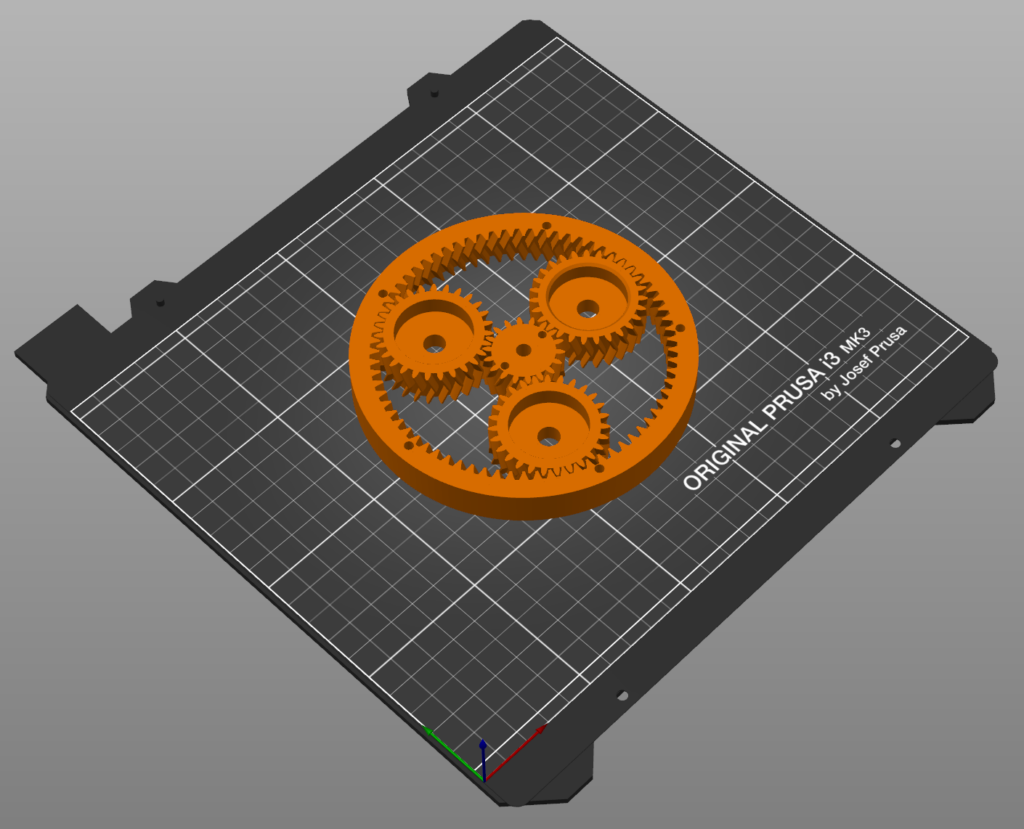
To turn with more force, and at a lower speed, a speed reduction is necessary. This can be achieved with gears, belts, and many interesting mechanisms. For this example, a simple planetary gearbox was generated using some publicly available tools and incorporated into a 3D-printable CAD design with the M200 at its heart! Its rotational speed will be reduced 4x, giving four times the torque available, or ~2 newton-meters and reversing the rotation direction of the motor! Ryan Cahoon’s Planetary Gear Simulator is useful when planning how to use these types of gearboxes. Unique zirconium bearings, popularized by the spinner fidget toys, are used to host the planets of the gearbox, as their ceramic composition is not only low friction but immune to corrosion, even when immersed. This guide is broken down into three main sections—design, fabrication, and testing, with some general troubleshooting tips at the end.
Gearbox Design and Parts Selection
This gearbox is open source, with .stl files available for download and printing with FDM or SLA machines. The entire design is also available in Onshape, so it can be copied and easily modified to your application. While it’s possible to generate the gears with tooth profiles entirely within Onshape, to speed things up a handy OpensCAD script by Dr. Jörg Janssen was used to generate the planetary gear set.
An important design consideration for M200 based applications is appropriate levels of cooling. A motor mount that provides support for the planets and their bearings was kept from fully enclosing the M200, so that water can cool the stator during operation. The bearings and the bolts on-hand were not a precise match, and so some adapting shims also made it to the parts list. Finally, a three-pack of drill mounted brushes were sourced, with varying degrees of stiffness. Put it all together and we might have quite a device!
Parts and Tools
You Will Need
- 1x M200 Motor (standard variation)
- 1x Basic ESC
- 1x M10-6.5MM-LC WetLink Penetrator
- 1x Thruster Commander
- 3″ Series Watertight Enclosure
- 1x 4S Lithium-ion Battery (Blue Robotics or similar)
You will also need:
- 3D print files (download from here)
- Drill mounted brush (we used this pack of varying stiffness bristles, but the design could be adapted to spin many different things!)
- Access to a filament-style 3D printer (PETG filament recommended, PLA acceptable)
- 3x Zirconia oxide ½” bearings (also known as ceramic bearings)
- 3x M8x25 mm bolts
- 5x M4x45 mm
- 2x M3x28 mm button head cap screw
- 4x M3x8 mm bolts
Fabrication
Preparing the 3D printed parts and planetary gear train
The planetary gear set is designed to be printed in place, assembled. Most slicers support a “geometric tolerance” feature that can be used to tune parts like this with surfaces that are very close together. Our printer made a gear set that was much too loose at -0.1mm, but -0.05mm spun freely and held together well. A print that is tough to turn by hand may not work well, at least initially, but once spun by the motor things may wear in!
We printed our parts with 0.2mm layer height, out of PETG with a 0.4mm nozzle, with 5 perimeters and 20% triangular infill. For stronger parts, increase the number of perimeters! It’s worth noting that 3D printed parts have no issues operating in marine applications, even at full ocean depth. However, they will flood with water as the bonds between layers do little to prevent water from entering as pressure increases. This can lead to water-logged devices that take ages to dry out, and salt build-up from frequent a possibility.
Download the 3D files and extract the contents. Print all seven .stl files in the M200_BRUSH_CAD_FILES folder.
Mounting the motor and brush
Once all the printed parts are ready, the M200 can be mounted.
The cable is fed through the hole in the mount, and motor secured with 4x M3x8mm bolts.
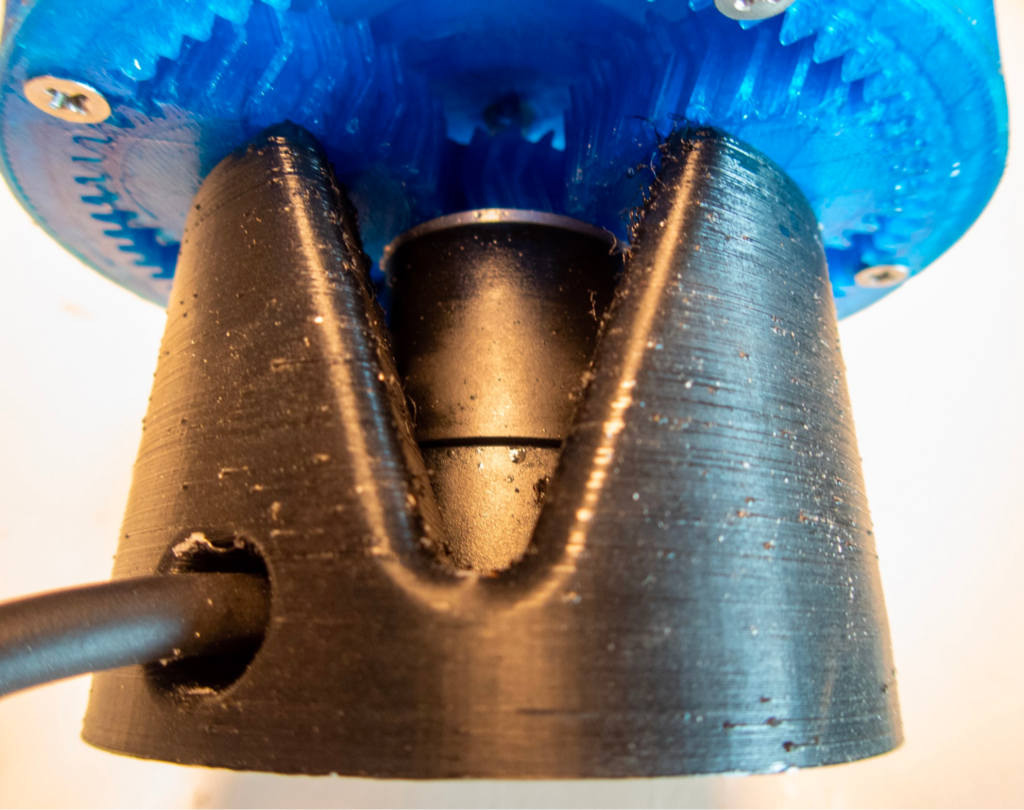
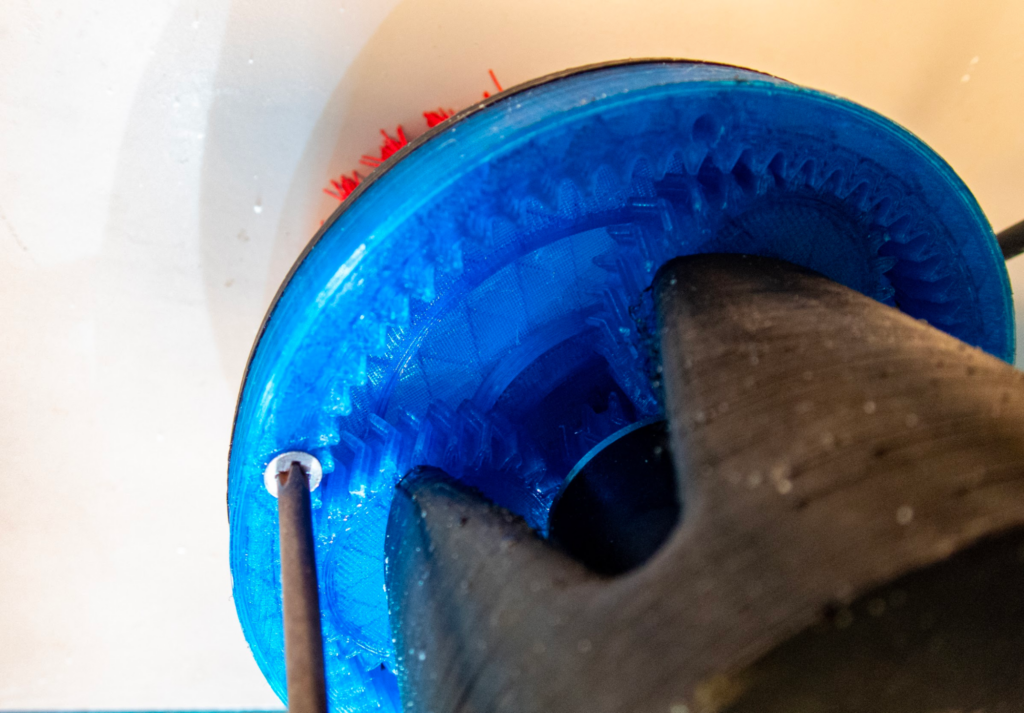
Next, the planetary gear train is attached to the motor with two M3x28mm bolts securing the sun-gear to the M200 rotor. While it’s possible to use an M8 tap on the planet gear mounting holes, we found a hot-air gun applied to the bolt, already held in its driving tool, made cutting the threads a cinch—but don’t over-tighten!
Heating bolt to tap planet bearing threads
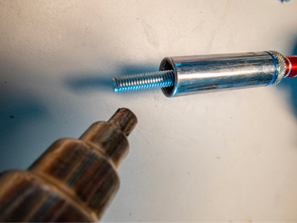
With the holes tapped and allowed to cool, the bolts can be removed and the zirconia oxide bearings popped into each planet gear. Install the M8x25mm bolts with printed shims through the bearing and into the mounting holes.
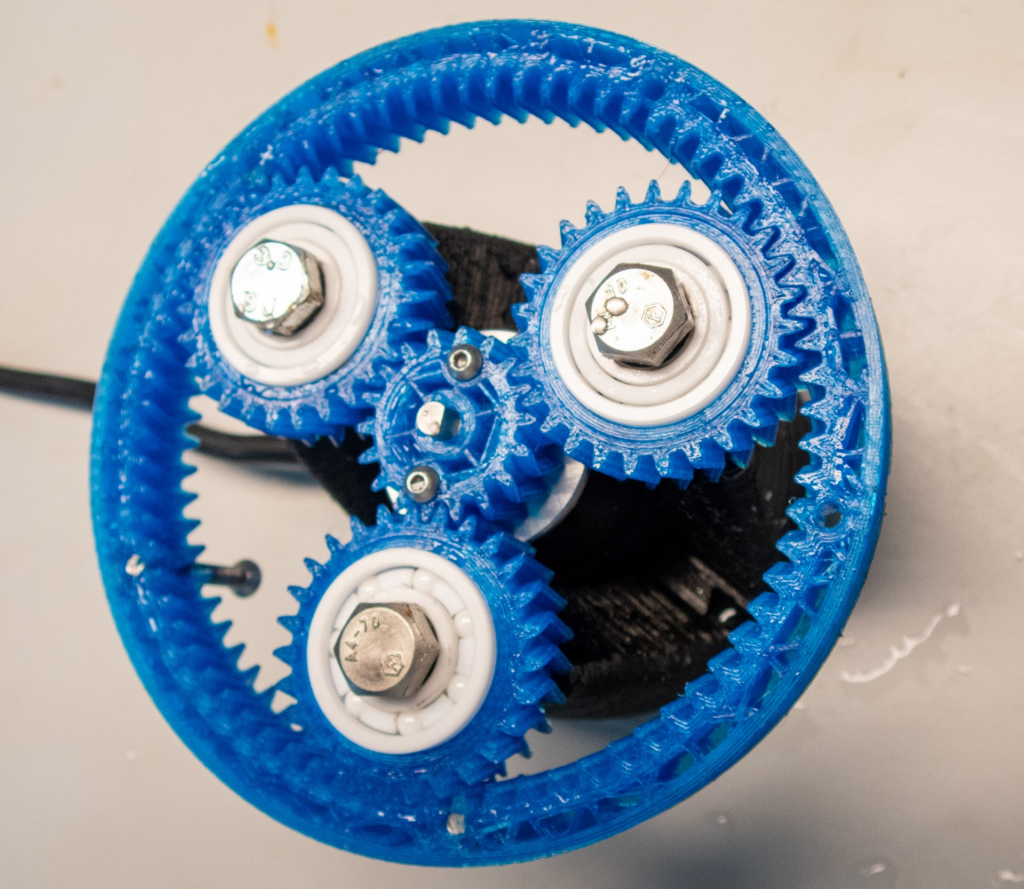
Zirconium bearings installed
The brush mount and gearbox cover piece is secured with 5x M4x45mm bolts around the perimeter. This will help prevent detritus from cleaning from entering the gears and accelerating wear or causing failures.
Planet gear cover / brush mount attached to output ring
Finally, we chose to glue the red brush into the gearbox cover, after trying the other two stiffness options and finding it the most rigid. A separate cylindrical piece with hex cutout was used as a spacer for the brush’s attachment, and this entire assembly was glued into the business end.
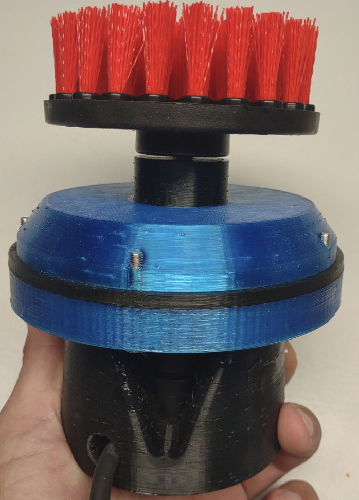
Brush and black spacer glued into gearbox cover at top
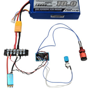
Preparing the battery and control enclosure
If you won’t be fully submerging the electronic components, you may not need to waterproof your battery and control electronics. The three wires of a 3-phase brushless motor can be extended, even beyond the standard length of our M200 and T200 units. However, this can lead to diminished efficiency and ESC issues. To use this underwater brush in some fun tests, a 3” series Blue Robotics enclosure was prepared with a 4S battery, Thruster commander, switch, vent and blanking bolts. The Thruster Commander is setup with the external switch connected to the outer switch pins, replacing the jumper, which will allow the motor to simply switch on and off. The speed is pre-set, before submersion, by the potentiometer that stays inside the enclosure, connected to the speed channel. The ESC is connected to either the left or right channel output. The endcap and electronics were assembled, and threaded between the battery and tube wall, so that the connection between the battery and the ESC was made at the opposite end of the tube from the thruster commander and switch. We have guides that explain how to connect the Blue Robotics Switch and use the Thruster Commander linked below.

Guide to the Thruster Commander
Turning a Thruster On and Off with a Thruster Commander
Watertight Enclosure (WTE) User Guide
Final assembly and preparation
Once all the pieces are together, it’s time to give it a twirl! With your fingers, that is. It should be easily possible to rotate the M200 motor. The entire gearbox should also be back-driveable, so if you twist the output ring while holding the motor base, the motor should spin very rapidly. If you encounter much resistance to motion with either approach, you may need to loosen the bolts securing the planet bearings to reduce the friction.
It’s always good to assemble the electronics and test on the bench before heading out to the field. Remember, the M200 Motor should not be operated dry for more than a few seconds to reduce the risk of heat damage to the water-lubricated sheave bearings inside. Once the switch has been verified to turn on the motor at a (initially low) potentiometer set-point, the enclosure can be sealed up and operation again tested. You’re now ready to take it out for a spin!
Testing
Lots of things get very dirty, very quickly in the ocean—primarily because it’s so incredibly biologically active! But while biofouling can be gross, humanity’s own impact on the ocean is far more disturbing. So what better opportunity to test the effectiveness of a cleaning tool than at a harbor cleanup? We joined with some friends at an Ocean Defenders Alliance organized harbor cleanup and took momentary breaks from removing trash from the ocean to wield our M200 brush contraption against…tires. Often used as fenders, tires are found in impressive quantities, and can be heavy, slippery, and hard to move! The brush spun with impressive force, and no amount of pressure would stop rotation, at least at the throttle level tested. The bristles were not quite stiff enough to remove the more persistent growths, but higher speeds or a different brush may prove more effective! Watch the video here.
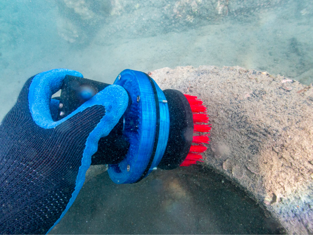
Before
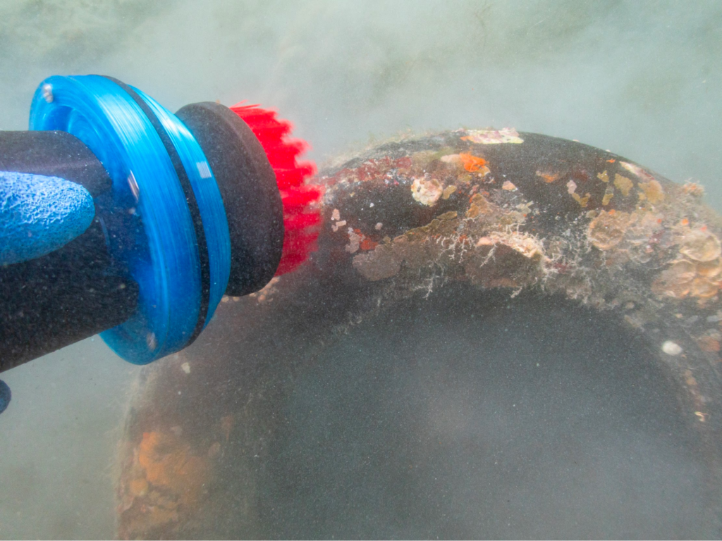
After
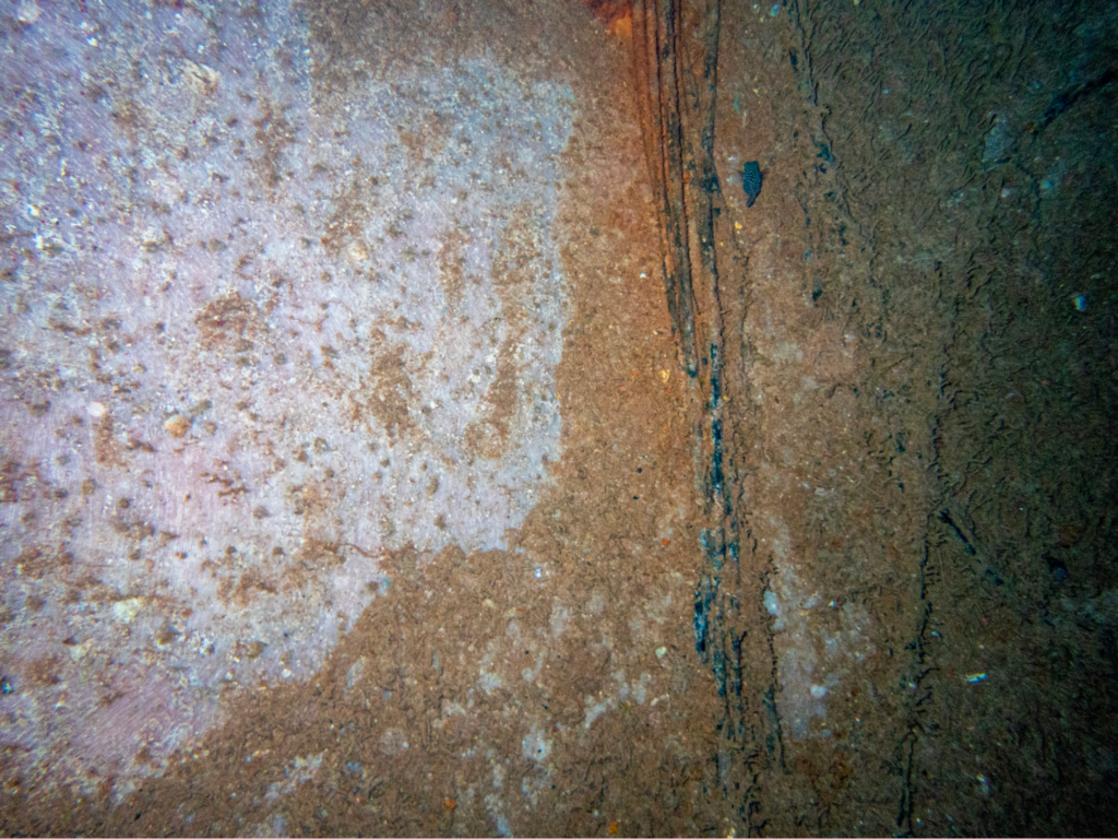
Brush cleaned area on the left, concrete pipe biofouled on the right.
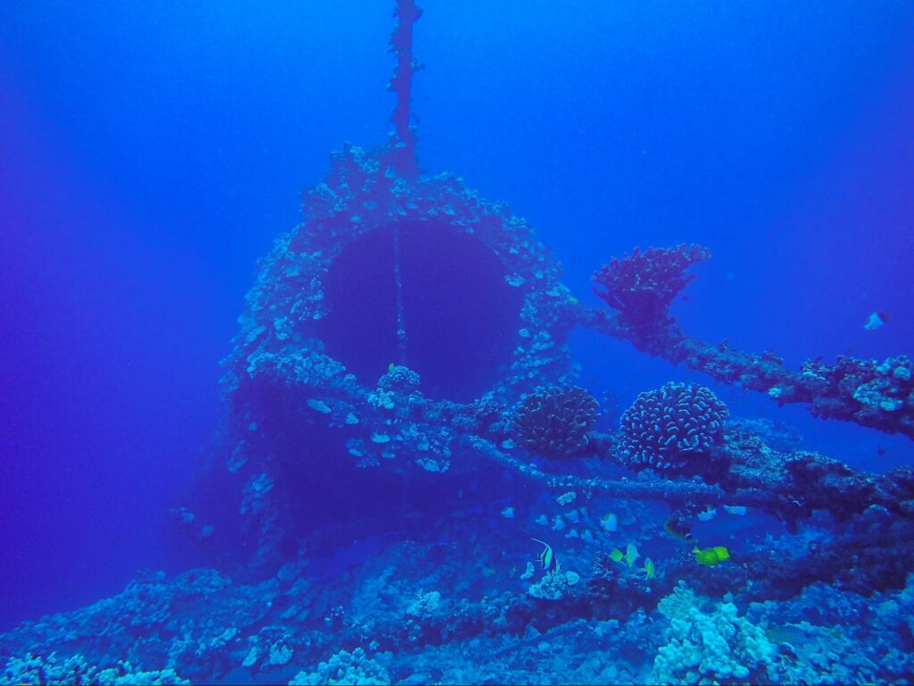
The pipe
Troubleshooting
Gear-train is not easy to turn by hand or very loose and wobbly
- If wobbly, the print may have been made with too large of a gap between surfaces. Adjust slicer settings to make a tighter fit by adjusting the horizontal or XY compensation value to a higher, or even positive value.
- If tight, the print may have been made with to little of a gap between surfaces. Adjust slicer settings to make a looser fit by adjusting the horizontal or XY compensation value to a lower, or negative value.
Thruster commander does not start motor
- Verify the ESC control wires are still connected, in the correct orientation and didn’t pull out while assembling and connecting to the battery!
- If the motor shakes but does not spin, verify all three motor wires are connected.
- Check the electrical connection to the switch and if it is fully screwed into its penetrator bolt.
- Double check the potentiometer is plugged in, in the correct orientation, and is set slightly above or below the center (detent) point of its rotation.
Feedback
We’re always trying to improve our documentation, instructions, software, and user experience. If you’d like to leave feedback about how we can make this guide better, let us know here.
Authors

Tony White
Tony White earned his Mechanical Engineering degree from Georgia Tech in 2012 and began his career with large autonomous hydrographic survey vessels with C&C Technologies (Louisiana) and ASV Ltd. (England). He later moved to Los Angeles to join Ocean Lab, where he helped design and deploy a swarm of 50 marine surface drones—the “Data Diver”—his first major project using Blue Robotics components. After some aquaculture experience in Los Angeles, he went on to Forever Oceans in Hawaii (and Panama), where he developed innovative camera monitoring systems and resident BlueROV2 platforms for remote fish mortality extraction. Since 2023, Tony works in Blue Robotics’ Product Experience and R&D departments, where he assists customers with applications and tests both in-house and third-party products, the latter evaluated for potential resale on the Blue Robotics “Reef.”