
Integrating the Omniscan 450 FS on the BlueROV2
The Cerulean Omniscan 450 FS Imaging Sonar features a 100-meter range and tall 50-degree vertical beamwidth, making it a powerful tool for locating and navigating to targets on the seafloor when installed on the BlueROV2. This guide will walk you through the installation process for one or multiple Omniscans on the BlueROV2.

Cerulean provides great documentation for the Omniscan 450 FS and SonarView software. Once your integration is complete, be sure to check out their guides for usage information and helpful tips.
Kit Contents
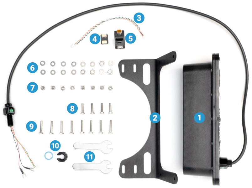
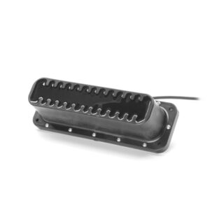
- 1 x Cerulean Omniscan 450 FS
- 1 x Omniscan 450 FS mounting bracket
- 1 x 150 mm JST GH to JST GH twisted pair cable (BR-100557)
- 1 x 4-position JST GH to JST GH coupler (BR-100509)
- 1 x RJ45 to JST GH adapter (BR-100555, not used for installation)
- 16 x M4 washer (BR-103527)
- 8 x M4 lock nut (BR-102250)
- 4 x M4x16 hex head cap screw (BR-103528)
- 8 x M4x20 hex head cap screw (BR-103519)
- 1 x M10 bulkhead nut & -013 O-ring (BR-100167-010)
- 2 x 7 mm wrench (BR-103514)
2D Position Tracking
SonarView supports 2D position tracking in the sonar output image. There are two ways to enable this feature:
- Receive external position data, such as from a Doppler Velocity Log (DVL).
- Use two or more Omniscan 450 FS sonars simultaneously to enable doppler mode.
Mounting Options
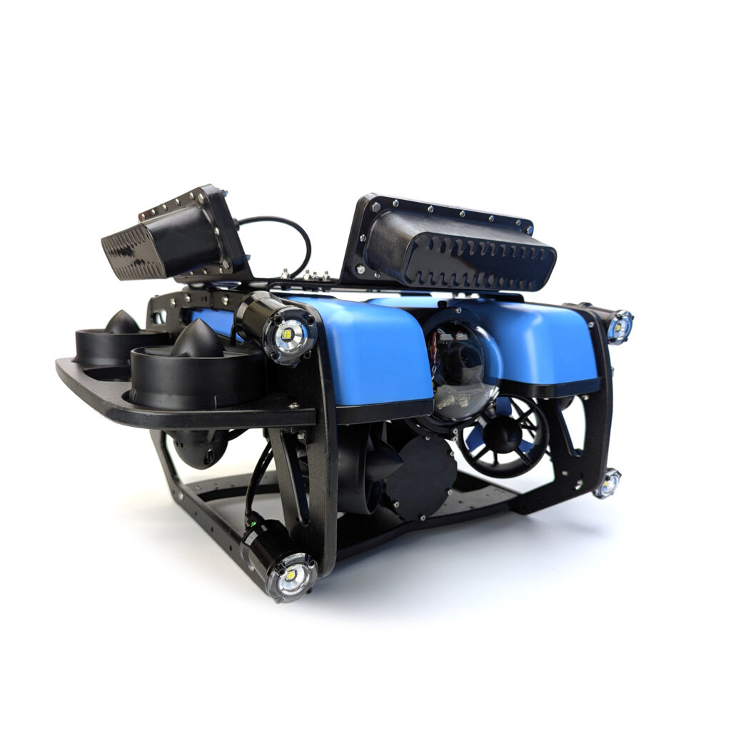
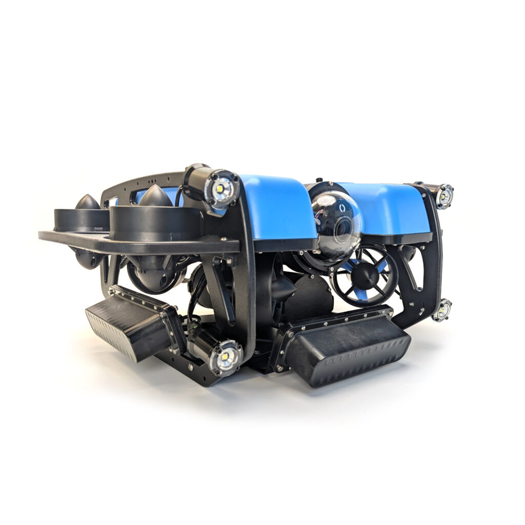
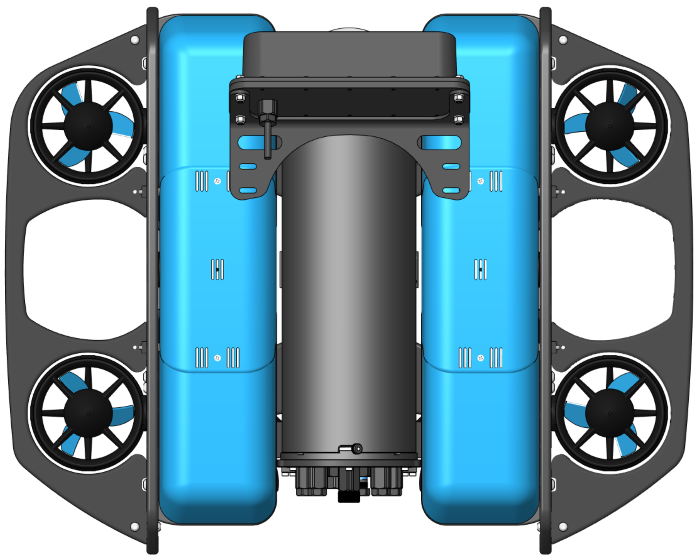
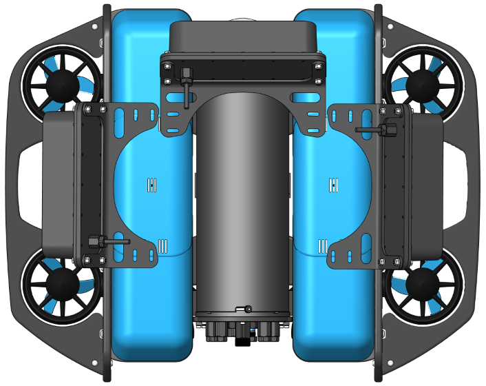
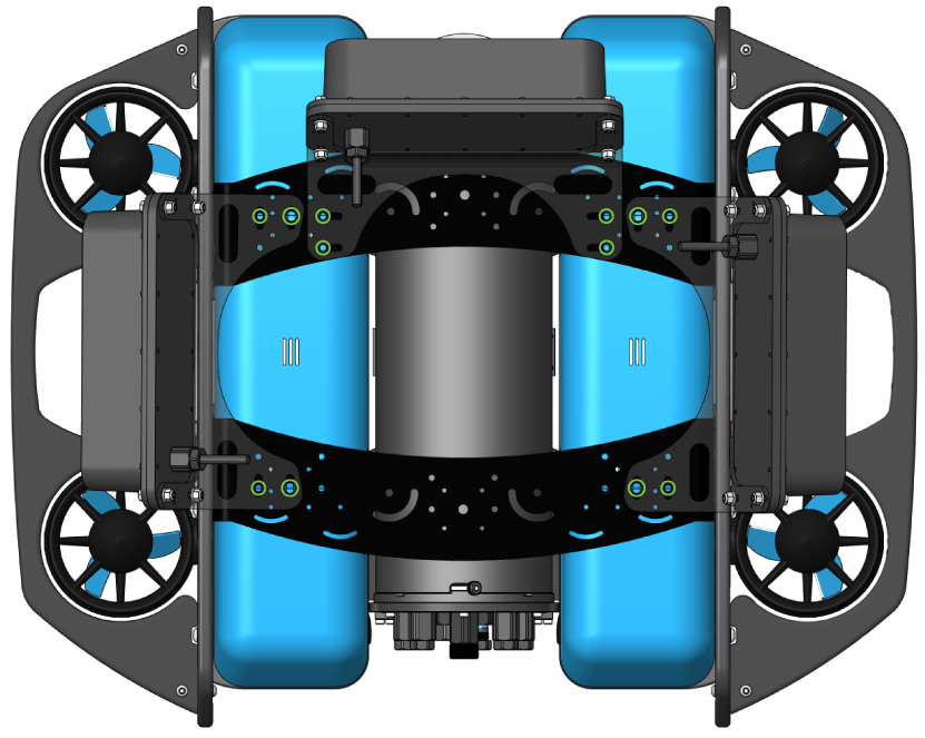
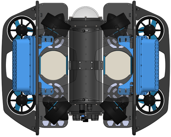
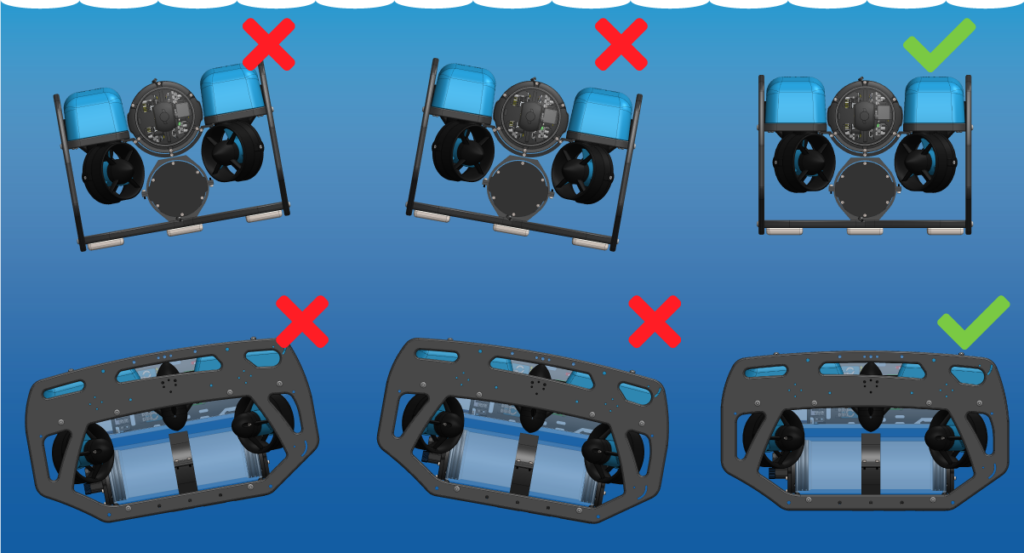
The Omniscan 450 FS can be mounted either on top of the BlueROV2 or on the bottom frame panel. Both options offer the same performance, so choose the placement that best suits your ROV setup and existing accessories. The images below show the BlueROV2 equipped with dual Omniscans.
To mount the Omniscan on top, you will need a Roof Rack. If installing multiple Omniscans, two Roof Racks are required.
The Omniscan can be mounted directly to the ROV by drilling mounting holes in the bottom panel.
Mounting a Single or Multiple Omniscans
You can use a single Omniscan or multiple Omniscans simultaneously. Mounting multiple Omniscans not only scans a larger area but also enables 2D position tracking in SonarView (“Doppler mode”).
When using a single Omniscan, it is typically best to mount it forward-facing.
To enable 2D position tracking with multiple Omniscans, the sonars must be mounted at right angles to each other. If the first sonar faces forward, mount the additional sonars facing either port or starboard.
Parts and Tools for Installation
In addition to the Omniscan 450 FS kit, you will need the following to complete the installation:
- 1 x M10 Bulkhead Wrench
- 1 x 2.5 mm hex driver
- 1 x #2 Phillips head screwdriver
- Silicone grease (Molykote 111)
- Cable ties for cable management
- Optional: 7 mm socket and ratchet. The kit includes 7 mm wrenches but a socket and ratchet makes installation easier
You will also need the following to top mount the Omniscan 450 FS:
- 1 x Roof Rack, or 2 x to mount multiple Omniscans
- 1 x 3 mm hex driver
You will also need the following to bottom mount the Omniscan 450 FS:
- Power drill
- 4.5 mm (~3/16 inch) drill bit
- A marker
Preparing the BlueROV2
To install the Omniscan, you will need to open the BlueROV2 Electronics Enclosure and remove a bulkhead penetrator. To do this, you will need:
- 1 x 2.5 mm hex driver
- 1 x M10 Bulkhead Wrench
If you’re unsure about any step in this section, more detailed instructions can be found in the Servicing the BlueROV2 section of the BlueROV2 Operation guide.
1. Make sure your BlueROV2 is completely powered off by disconnecting the battery.
2. Use the 2.5 mm hex to remove the M3x16 mounting screws that secure the enclosure mounting clips to the cradles, remove the PRV or vent plug, and remove the Electronics Enclosure tube from the Electronics Enclosure assembly.
3. Choose one of the blank penetrators in the middle of the end cap and use the M10 Bulkhead Wrench to remove it. If you are installing multiple Omniscans, remove a blank penetrator for each one.
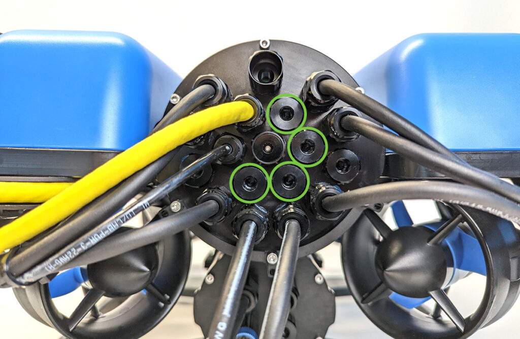
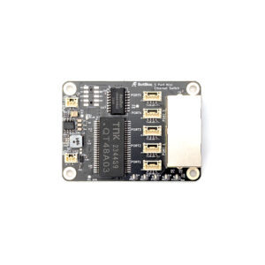
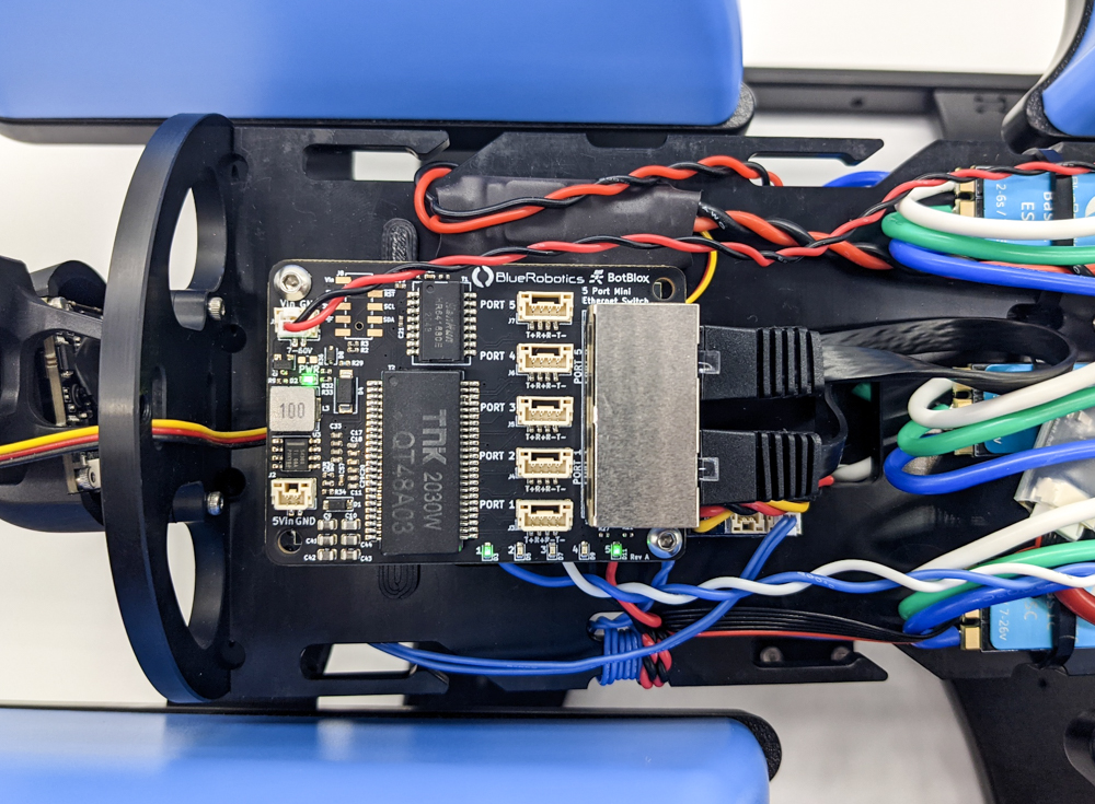
4. Install the Blue Robotics Ethernet Switch if you have not done so already. Follow the Ethernet Switch installation guide to install the Ethernet Switch in your ROV. Come back to this guide when you are done.
Hardware Installation
Screw sizes are given in metric and follow the format M#x#. The first number (M#) represents the screw’s diameter—a larger number indicates a thicker screw. The second number represents the length—a larger number means a longer screw.
Installing the Bulkhead Penetrator
To install the Omniscan bulkhead penetrator into the end cap, you will need the following parts and tools:
- The Omniscan(s)
- 1 x M10 bulkhead nut (included with the Omniscan)
- 1 x -013 O-ring (included with the Omniscan)
- 1 x M10 Bulkhead Wrench
- Silicone grease (Molykote 111)
1. Take a moment to consider where you will install the Omniscan on the ROV and how you will route the cable. If mounting it on the bottom of the ROV, route the cable from its mounting point through the frame to the rear of the ROV before installing the bulkhead penetrator.
2. Wipe the exterior surface of the end cap around the hole where you removed the blank bulkhead penetrator. Ensure the O-ring seating area is clean and free of dust or debris.
3. Inspect the bulkhead O-ring to make sure it is not dirty or damaged.
4. Lubricate the O-ring with a thin layer of silicone grease and install it in the groove on the underside of the bulkhead penetrator.
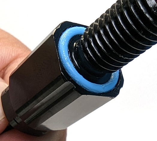
5. Insert the bulkhead in the hole and fasten the bulkhead nut on the opposite side. Tighten the nut by hand until it is finger-tight, then use the bulkhead wrench to fully secure the connection. When properly installed, the bulkhead should be fixed in place with no rotation, and you should not be able to loosen it by hand.
Wire Connections and Reassembly
For this step you will need:
- 1 x 150 mm JST-GH to JST-GH twisted pair cable (included with the Omniscan)
- 1 x 4-position JST GH to JST GH coupler (included with the Omniscan)
- 1 x #2 Phillips head screwdriver
- 1 x 2.5 mm hex driver
- The M3 mounting screws you removed from the ROV previously
- Silicone grease (Molykote 111)
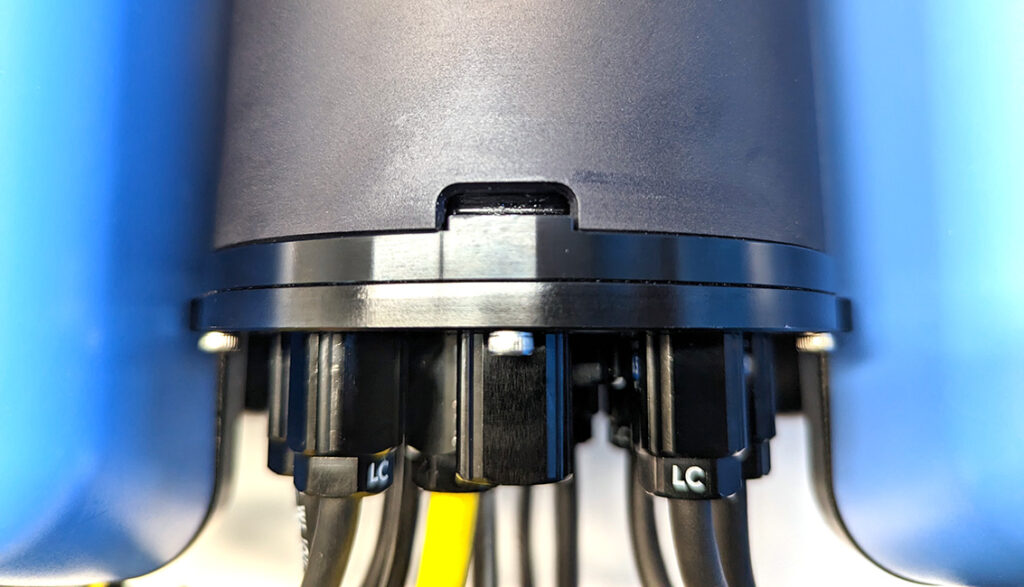
1. Use the #2 Phillips head screwdriver to connect the power wire spade connectors at the end of the Omniscan cable to any available screw terminals on the ROV power terminal blocks. Connect the black power wire to the terminal block with the other black wires and the red power wire to the terminal block with the other red wires.
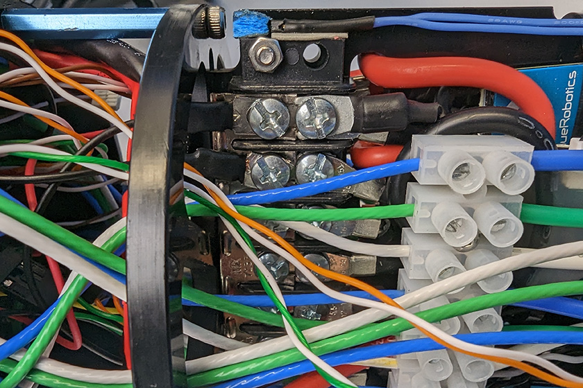
All the black power wires.
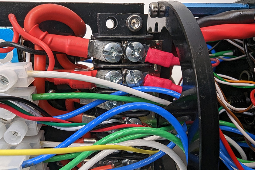
All the red power wires.
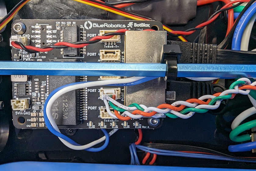
2. Connect the 150 mm JST GH twisted pair cable to the 4-position JST GH to JST GH coupler then connect coupler to the 4-position JST GH connector at the end of the Omniscan cable.
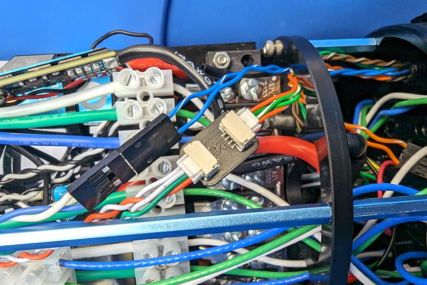
Connect the other end of the 150 mm JST GH twisted pair cable to an open port on the Ethernet Switch. Do not use ports 1 or 5 as these are already in use.
3. If you are using multiple Omniscans, repeat the steps to connect them. This completes all of the wire connections inside the ROV. You can now close up the ROV. Apply a thin coat of silicone grease to the two radial O-rings on the O-ring flange and the inner end of the tube.
4. Reinstall the tube and dome assembly onto the flange. If the ROV has a locking-style enclosure, ensure the rotation locking tab sits inside the slot in the tube.
5. If your ROV has a locking cord, insert it through the slot.
6. Reinstall the PRV or vent plug back in the bulkhead. Turn the plug clockwise until it stops to seal it.
7. Place the Electronics Enclosure on the enclosure cradles and line up the mounting clips with the screw holes on the cradles. Use the 2.5 mm hex to install the screws through the mounting clips and into the front and rear enclosure cradles
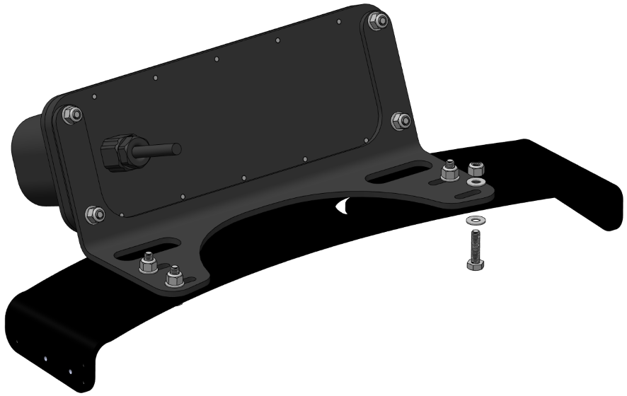
Installing the Brackets
To install the brackets you will need:
- Omniscan 450 FS mounting bracket (included with the Omniscan)
- 4 x M4x20 hex head screw for each Omniscan (included)
- 8 x M4 washer for each Omniscan (included)
- 4 x M4 lock nuts for each Omniscan (included)
- 2 x 7 mm wrench (included) or 7 mm socket and ratchet (not included)
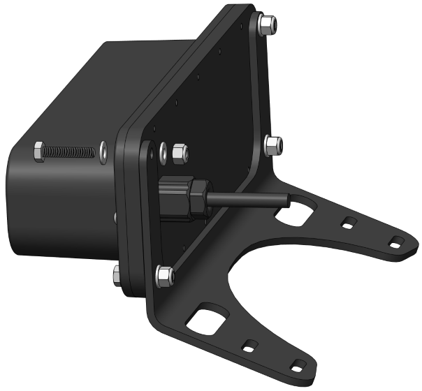
Mount the bracket to the Omniscan using the four corner mounting holes.
- Use one M4x20 screw, one M4 lock nut, and two washers per hole.
- Place one washer between the screw head and the Omniscan and another between the nut and the bracket.
- Hold the screw head with one of the included 7 mm wrenches while tightening the nut with the other wrench. Alternatively, use a ratchet with a 7 mm socket if available.
The following sections cover mounting the Omniscan to the ROV. If mounting it to the top, go to the Top Mounting the Omniscan 450 FS section. If mounting it to the bottom, skip to the Bottom Mounting the Omniscan 450 FS section.
Top Mounting the Omniscan 450 FS
For this section you will need:
- Roof Rack(s)
- 4 x M5x12 button head cap screw for each Roof Rack (included with Roof Rack)
- 4 x M4x16 hex head screw for each Omniscan (included)
- 4 x M4 lock nuts for each Omniscan (included)
- 8 x M4 washer for each Omniscan (included)
- 2 x 7mm wrench (included) or 7mm socket and ratchet (not included)
- 1 x 3 mm hex driver
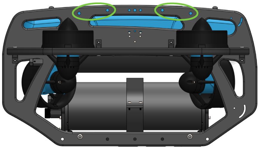
For a forward facing Omniscan, mount the bracket to the top of the Roof Rack using the holes shown below.
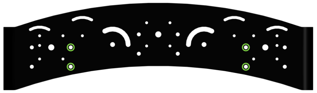
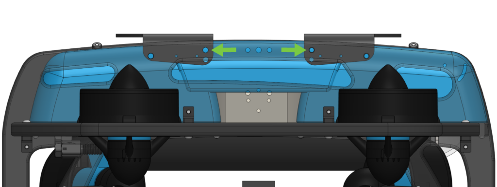
If you are installing multiple Omniscans, the side-facing Omniscans will span across two Roof Racks using the holes shown below.
1. Use the M4x16 hex head screws, locking nuts, and washers to secure the bracket to the Roof Rack.
- Insert the hex head screw from underneath the Roof Rack.
- Place a washer between the screw head and the Roof Rack and another between the nut and the bracket.
- If installing side-facing sonars across the Roof Racks, leave the fasteners slightly loose to allow for minor adjustments when securing the Roof Racks in the next step.
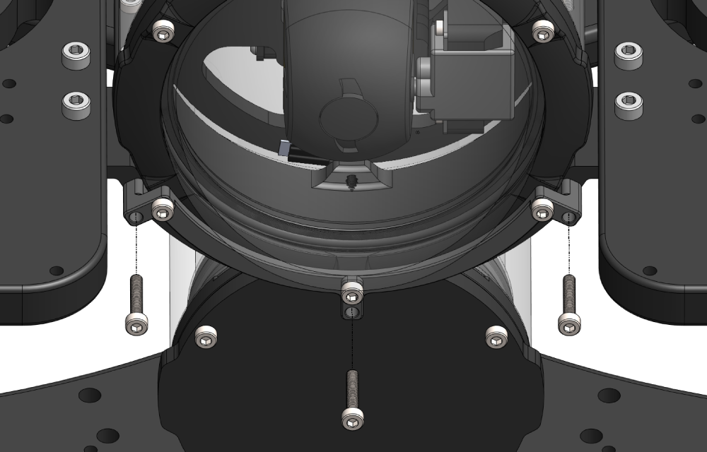
2. With the Omniscan mounted on the Roof Rack, install the Roof Rack to the ROV frame using M5x12 button head screws and 3 mm hex driver. The front and rear mounting points are shown below.
Use the higher set of mounting holes on the rack to mount it level.
3. With the Roof Racks fully secured, use the flat 7 mm wrenches to fully tighten the bracket fasteners if they were left slightly loose in the earlier step.
Bottom Mounting the Omniscan 450 FS
For this section you will need:
- 4 x M4x20 hex head screw for each Omniscan (included)
- 4 x M4 lock nuts for each Omniscan (included)
- 8 x M4 washer for each Omniscan (included)
- 2 x 7mm wrench (included) or 7mm socket and ratchet (not included)
- Power drill
- 4.5 mm (~3/16 inch) drill bit
- A marker
The mounting locations for forward facing and side facing sonars are shown below.
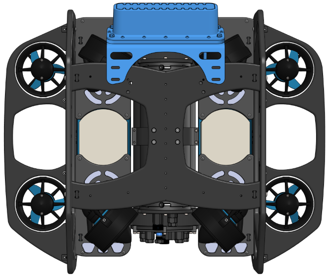
Forward facing mounting location.
Side facing mounting locations.
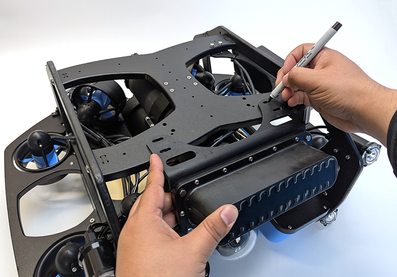
1. Remove any ballast weights that are in the way and use the bracket as a template to mark the location of the mounting holes on the bottom panel.
2. Use a drill with a 4.5 mm or 3/16 inch bit to drill mounting holes through the bottom panel.
3. Use the M4x20 hex head screws, locking nuts, and washers to secure the bracket to the bottom panel.
- For forward facing sonars, install the bracket under the bottom panel to provide enough clearance between the thrusters and the sonar.
- For side facing sonars, install the bracket on top of the bottom panel.
- Place a washer between the screw head and the panel and another between the nut and the panel.
Cable Management
Good cable management ensures that loose cables are secured to the ROV frame, preventing them from getting caught on obstacles or damaged by the thruster propellers. Use cable ties to fasten the cable to the frame, ensuring there are no loose sections. Once secured, double-check that no cables can reach a thruster propeller.
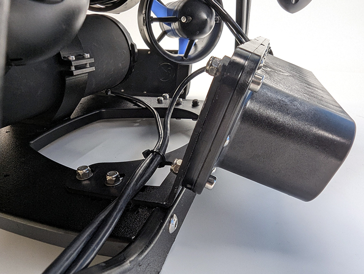
Example cable management for bottom mounted sonars.
Adjusting the Ballast on the Frame
The sonar and rack add weight to the BlueROV2 frame, so the ROV’s ballast must be adjusted to maintain neutral buoyancy and balance in the water. To compensate, remove or reposition ballast weights on the bottom of the frame as needed.
For detailed instructions on adjusting ballast, refer to the Servicing the BlueROV2 section in the BlueROV2 Operation guide.
Software Setup
The Omniscan 450 FS output is viewed using SonarView. SonarView can be installed as a BlueOS extension or as an application on your computer.
Installing the SonarView Extension
1. Power up your BlueROV2 and connect it to your computer. If you don’t know how to do that, please check out the BlueROV2 Software Setup guide first.
2. Access BlueOS (the BlueROV2’s operating system) by typing 192.168.2.2 or blueos.local into a web browser address bar.
3. Connect the BlueROV2 to a Wi-Fi network.
4. Extensions support requires BlueOS version 1.1.0 or later. If your system is out of date, follow these instructions to update BlueOS then come back to this guide.
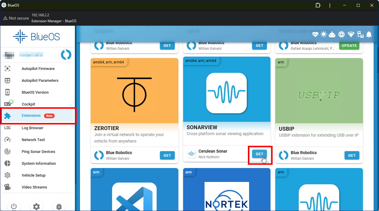
5. Go to the Extensions menu in BlueOS and install the SONARVIEW extension by Cerulean Sonar.
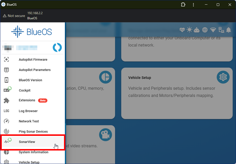
6. After the extension is installed, SonarView will appear in the left sidebar.
Installing the SonarView Application
Go to this page and follow the installation instructions for your operating system.
Increase ArduSub Message Rates
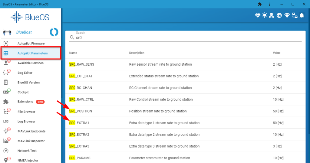
1. In BlueOS, click on Autopilot Parameters.
2. In the search box, type “sr0”. Find the SR0_POSITION and SR0_EXTRA1 parameters and set them both to “50”.
Configure QGroundControl
If you are using QGroundControl, it needs to be configured to allow the vehicle to control message rates. If you’re not using QGroundControl, skip this section!
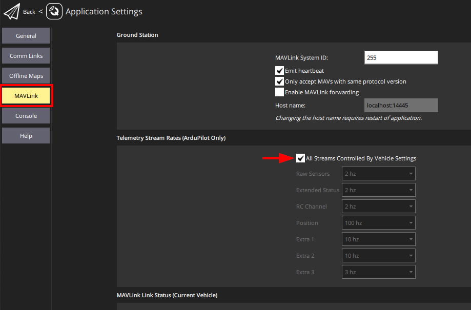
Open QGroundControl, click the Q icon in the top left corner, then click Application Settings.
Click MAVLink on the left side, then enable All Streams Controlled By Vehicle Settings. Restart QGroundControl.
Using a Single Omniscan
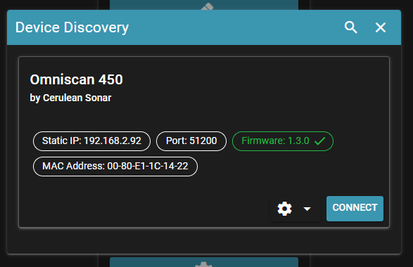
1. Open SonarView and click Device Discovery. On the next screen you should see the Omniscan as a detected device. Click on CONNECT to connect to it.
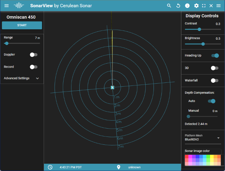
2. On the main user interface screen, click on START to start pinging. The sonar image will begin to fill in in the main display area as you move and rotate the ROV. Click on STOP to stop pinging.
SonarView can use the BlueROV2 heading and position (when available) for better situational awareness, follow these instructions to set up a session configuration to enable this.
SonarView has many more options to configure sonar settings and display settings, visit the SonarView documentation to learn more.
Setting Up Multiple Omniscans
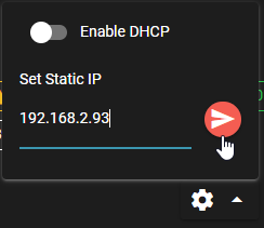
By default, every Omniscan has the static IP address 192.168.2.92. Each Omniscan must be configured with a unique IP address before use. To set the IP address:
1. Open SonarView and click Device Discovery. On the next screen you should see each Omniscan listed as a detected device.
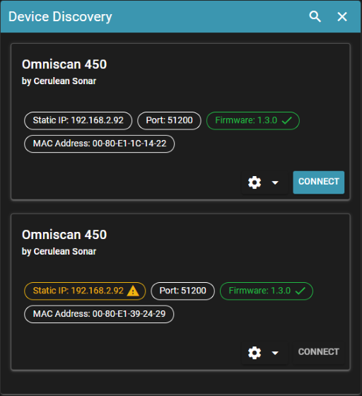
2. Click on the settings icon of the Omniscan with the duplicate IP address and set the last digit of its address to something different, 192.168.2.93 for example. Click on the red arrow to confirm it. Repeat for any other connected Omniscans.
3. Once every Omniscan has a unique address, you need to determine which is which. Connect to each Omniscan individually from the Device Discovery screen. Click on START to start pinging, you should be able to hear a clicking sound coming from the device. You may also be able to feel the clicking by running your finger over the face of the transducer with slight pressure. Once you’ve determined which device is clicking, make a note of its IP address and its position on the ROV.
Creating a Session Configuration
Now that each sonar is identified and has a unique IP address, we must setup a session configuration:
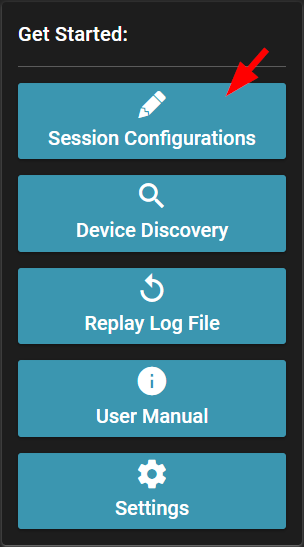
1. From the SonarView main menu, click on Session Configurations.
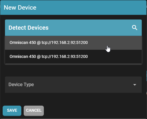
2. In the Session Configurations screen click on ADD DEVICE. In the next window, click on Detect Devices and you should see each connected Omniscan and its IP address. Click on one to configure it.
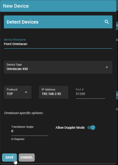
3. On the next screen, give the Omniscan a name that will help you distinguish it. Here you will also configure its position on the ROV by setting its Transducer Angle. If you don’t know which Omniscan is which, follow the instructions in step 3 of the previous section.
- The transducer angle starts at 0 degrees facing forward, with positive angles to the right (starboard), and negative angles to the left (port).
- For the forward facing sonar, leave the transducer angle at 0.
- For a starboard facing sonar, set the angle to 90 degrees.
- For a port facing sonar, set the angle to -90 degrees.
The other settings can be left at their defaults. Click on SAVE when you are done. Repeat for all connected Omniscans.
4. Click on ADD VEHICLE.
- Enter a vehicle nickname.
- The Platform Mesh is the model used in the SonarView display. Set it to BlueROV2 for an accurate look.
- Set the Protocol to mavlink2rest.
- Click on SAVE when you are done.
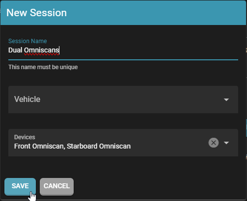
5. Click on ADD SESSION to make a new session. On the next screen, give the session a name, “Dual Omniscans” for example. Use the drop downs to add the BlueROV2 and all Omniscans to the session. Click on SAVE when you are done.
6. That’s it! This session will now appear in the Device Discovery menu. Click on CONNECT next to the session then START to start pinging, all Omniscan devices that are defined in that session will be used simultaneously.
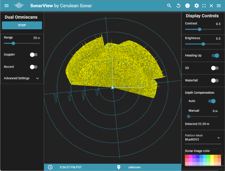
While using multiple Omniscans, toggle the Doppler setting to enable 2D position tracking in the SonarView display.
SonarView has many more options to configure sonar settings and display settings, visit the SonarView documentation to learn more.
Feedback
We’re always working to make our guides, software, and user experience even better. If you have any ideas on how we can improve this guide, feel free to let us know here.