
Integrating the MarineSitu C3 Stereo Camera on the BlueROV2
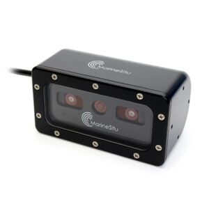
The MarineSitu C3 captures stereo imagery, making it a powerful tool for applications like advanced marine robotics, and environmental monitoring. This guide will show you how to install it on the BlueROV2 and point you to useful software resources.

Kit Contents

- 1 x C3 Stereo Camera
- 1 x Mounting bracket
- 2 x Rubber bumper feet
- 2 x M5x45 socket head screw
- 4 x M5x25 button head screw
- 4 x M5x10 button head screw
- 6 x M5 lock nut
- 1 x M10 bulkhead nut & -013 O-ring
- 1 x 3 mm hex key (not shown)
- 1 x Lens cover (not shown)
Parts and Tools for Installation
In addition to the C3 Stereo Camera kit, you will need the following to complete the installation:
- 1 x M10 Bulkhead Wrench
- 1 x 2.5 mm hex tool
- 1 x 4 mm hex tool
- 1 x #2 Phillips head screwdriver
- Silicone grease (Molykote 111)
- 8 mm wrench or small adjustable wrench
- Drill with 5.5 mm or 7/32 inch drill bit
- A couple cable ties for cable management
- A marker
Preparing the BlueROV2
To install the C3, you will need to open the BlueROV2 electronics enclosure and remove a bulkhead penetrator. You’ll need:
- 1 x 2.5 mm hex driver
- 1 x M10 Bulkhead Wrench
If you’re unsure about any step in this section, more detailed instructions can be found in the Servicing the BlueROV2 section of the BlueROV2 Operation guide.
1. Make sure your BlueROV2 is completely powered off by disconnecting the battery.
2. Use the 2.5 mm hex to remove the M3x16 mounting screws that secure the enclosure mounting clips to the cradles, remove the PRV or vent plug, and remove the electronics enclosure tube from the electronics enclosure assembly.
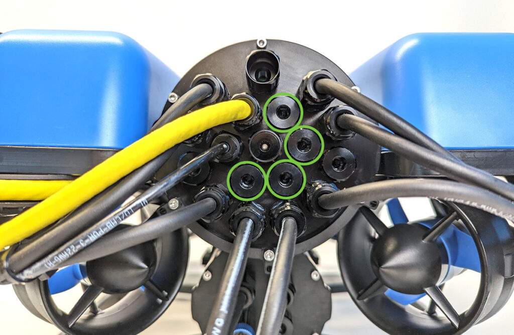
3. Choose one of the blank penetrators in the middle of the end cap and use the bulkhead wrench to remove it.
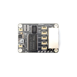
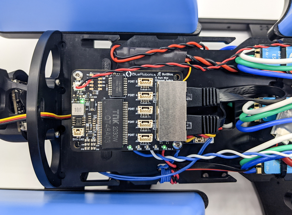
4. Install the Blue Robotics Ethernet Switch if you have not done so already. Follow the Ethernet Switch installation guide to install the Ethernet Switch in your ROV. Come back to this guide when you are done.
Hardware Installation
If you need help with any part of the assembly, please reach out to us here.
Screw sizes are given in metric and follow the format M#x#. The first number (M#) represents the screw’s nominal diameter in millimeters—a larger number indicates a thicker screw. The second number represents the length in millimeters—a larger number means a longer screw.
The C3 camera includes a lens cover. It’s a good idea to keep this cover on while you install the camera to prevent any damage to the lens.
Installing the Bulkhead Penetrator
To install the camera bulkhead penetrator into the end cap, you will need the following parts and tools:
- The C3 camera
- 1 x M10 bulkhead nut (located at the end of the cable)
- 1 x -013 O-ring (located at the end of the cable)
- 1 x M10 Bulkhead Wrench
- Silicone grease (Molykote 111)
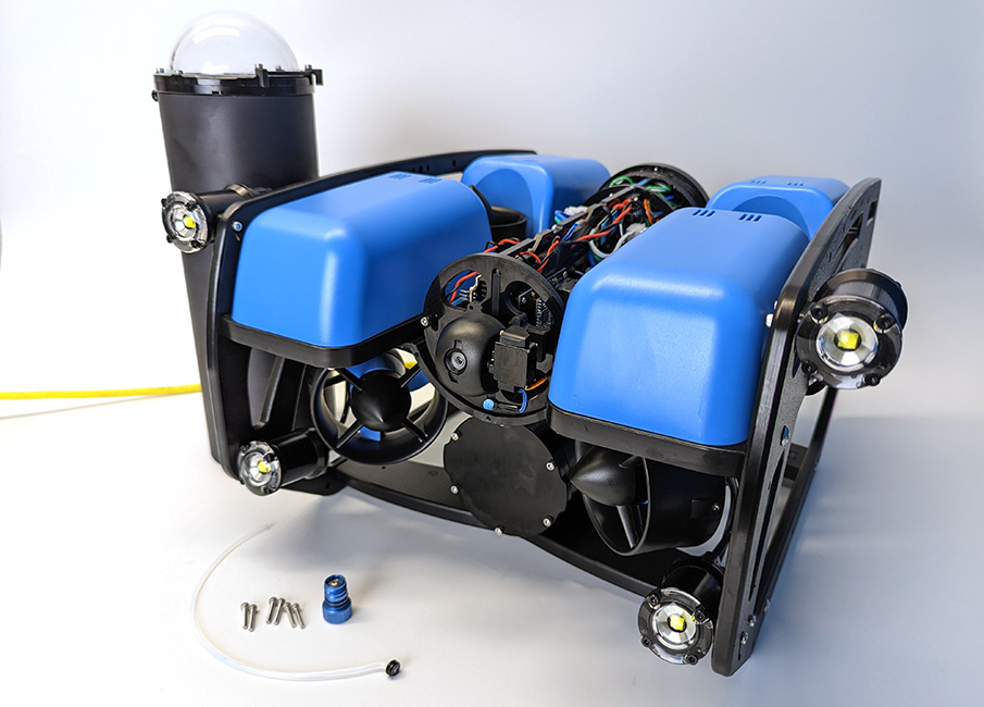
1. Place the camera in front of the BlueROV2 and route the cable through the frame to the rear of the ROV.

2. Remove the nut and O-ring from the end of the camera cable.
3. Wipe the exterior surface of the end cap around the hole where you removed the blank bulkhead penetrator. Ensure the area around the hole is clean and free of dust or debris.
4. Inspect the bulkhead O-ring to make sure it is not dirty or damaged. Lubricate the O-ring with a thin layer of silicone grease and install it in the groove on the underside of the bulkhead penetrator.
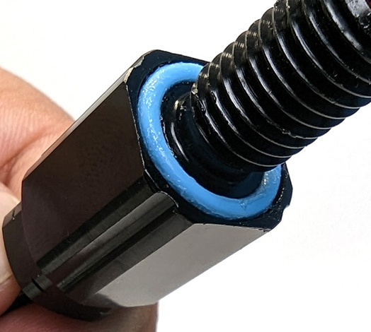
5. Insert the bulkhead in the hole and fasten the bulkhead nut on the opposite side. Tighten the nut by hand until it is finger-tight, then use the bulkhead wrench to fully secure the connection. When properly installed, the bulkhead should be fixed in place with no rotation, and you should not be able to loosen it by hand.
Wire Connections and Reassembly
For this step you will need:
- 1 x #2 Phillips head screwdriver
- 1 x 2.5 mm hex driver
- The M3 mounting screws you removed from the ROV previously
- Silicone grease (Molykote 111)
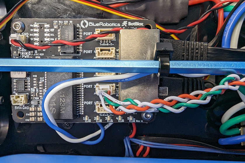
1. Use a #2 Phillips screwdriver to connect the camera’s red and black power wires to the BlueROV2 power terminal blocks:
- Connect the black wire to any available position on the terminal block with the other black wires.
- Connect the red wire to any available position on the terminal block with the other red wires.
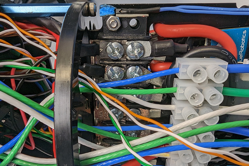
All the black power wires.
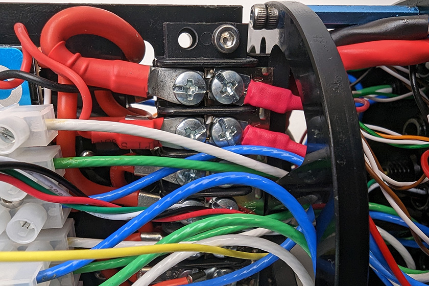
All the red power wires.
2. Connect the camera’s 4-wire Ethernet cable to an open port on the Ethernet Switch. Do not use ports 1 or 5 as these are already in use.
3. Reinstall the tube and dome assembly onto the flange. If the ROV has a locking-style enclosure, ensure the rotation locking tab sits inside the slot in the tube.
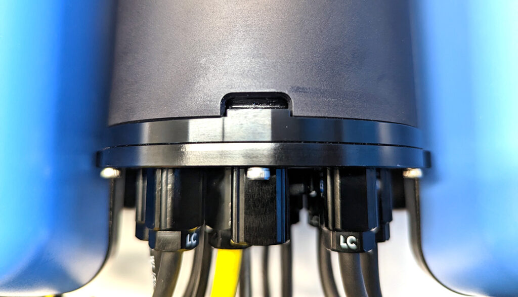
4. If your ROV has a locking cord, insert it through the slot.
5. Reinstall the PRV or vent plug back in the bulkhead. Turn the plug clockwise until it stops to seal it.
6. Place the Electronics Enclosure on the enclosure cradles and line up the mounting clips with the screw holes on the cradles. Use the 2.5 mm hex to install the screws through the mounting clips and into the front and rear enclosure cradles.
At this point the C3’s cable should be connected to the ROV and ready to mount to the frame.

Mounting the C3
In this section you’ll drill a few holes in the bottom panel of the ROV to mount the camera. You’ll need:
- 1 x Mounting bracket
- 2 x Rubber bumper feet
- 2 x M5x45 socket head screw
- 4 x M5x25 button head screw
- 4 x M5x10 button head screw
- 6 x M5 lock nut
- 1 x 3 mm hex key
- 1 x 4 mm hex tool
- 8 mm wrench or small adjustable wrench
- Drill with 5.5 mm or 7/32 inch drill bit
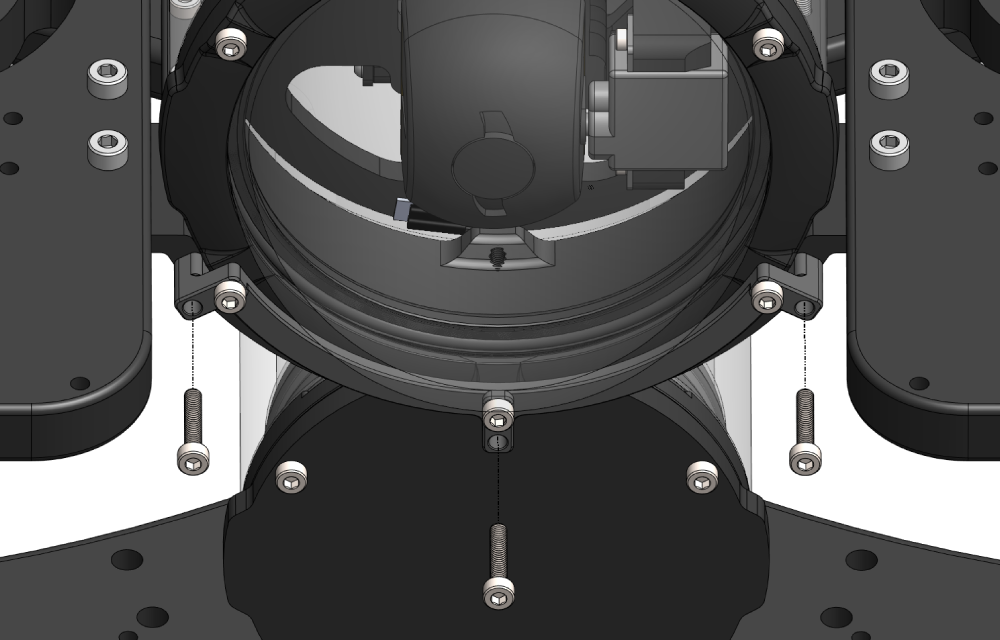
1. Flip the BlueROV2 upside down. At the front of the ROV, align the upper holes of the mounting bracket with the existing holes in the bottom panel, then mark the locations of the two lower holes.
- If your ROV doesn’t have any holes here to align to, center the mount and mark all four holes.

2. On both the front left and right sides of the bottom panel, mark a point roughly halfway between the slot nut and the ballast mounting hole for the bumper feet.

3. Use a drill with a 5.5 mm or 7/32 inch bit to make holes in all the locations you marked.

4. Use four M5x25 screws, four lock nuts, and the 3 mm hex key to secure the bracket to the bottom panel.

5. Insert an M5x45 screw into each bumper foot so the screw head sits inside the rubber foot, then secure each one to the bottom panel using two lock nuts and the 4 mm hex tool.

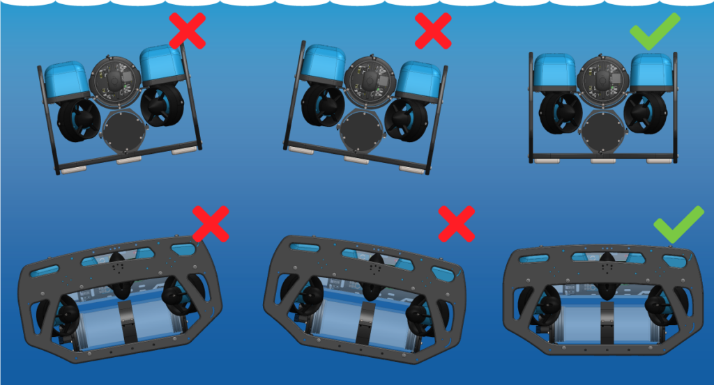
6. Flip the ROV upright and position the camera inside the bracket at the desired angle then use the M5x10 screws and 3 mm hex key to secure the camera in the bracket.
- It might be a tight fit in the bracket, this is normal. If needed, bend the sides of the bracket out a little to make room.
- You may want to organize and secure the camera cable to the frame before securing the camera in the bracket. See the Cable Management section.

Cable Management
Good cable management ensures that loose cables are secured to the ROV frame, preventing them from getting caught on obstacles or damaged by the thruster propellers. Use cable ties to fasten the cable to the frame, ensuring there are no loose sections. Once secured, double-check that no cables can reach a thruster propeller.

Adjusting the Ballast on the Frame
The camera adds weight to the BlueROV2 frame, so the ROV’s ballast must be adjusted to maintain neutral buoyancy and balance in the water. Remove or reposition ballast weights on the bottom of the frame as needed.
For detailed instructions on adjusting ballast, refer to the Servicing the BlueROV2 section in the BlueROV2 Operation guide.
Software Setup
This section covers how to configure BlueOS to access the camera over the ROV’s local network and points you to additional software resources.
Network Setup
The camera is configured as a DHCP client, so we must enable BlueOS’s DHCP server to access it on the ROV local network.
1. Power up your BlueROV2 and connect it to your computer. If you don’t know how to do that, please check out the BlueROV2 Software Setup guide first.
2. Access BlueOS (the BlueROV2’s operating system) by entering 192.168.2.2 or blueos.local into a web browser address bar.
3. Connect the BlueROV2 to a Wi-Fi network.
4. Make sure BlueOS is up to date. Older versions won’t support the steps that follow. Update to the latest stable release using the instructions here, then return to this guide.
5. Open the BlueOS networks menu from the top right corner, expand the eth0 device, and choose ENABLE DHCP SERVER.

6. After enabling the DHCP server for the first time, you may need to power-cycle the BlueROV2 (with the camera connected) so the camera can receive an IP address. After the initial setup, this will happen automatically.
Cockpit View Setup and Snapshots with Madrona
The Madrona extension provides an easy way to manage the C3 camera, configure commonly used pipelines, and run them on the device. It can be installed from the BlueOS Extensions store.
1. Access BlueOS and connect to Wi-Fi. If you don’t know how to do that, refer to Network Setup.
2. Go to the Extensions menu in BlueOS and install the MADRONA extension by MarineSitu Inc.

3. After it’s installed, open it from the BlueOS left sidebar. If the camera doesn’t show up as an available device, select DISCOVER DEVICES to search for it on the network.
The main Madrona interface you can choose stream profiles and start and stop pipelines:

- Expand DEVICE INFORMATION to view device info like the camera’s IP address.
- Select from available profiles.
- Changes the profile on the camera to the profile selected.
- Starts and stops video pipeline.
4. The default profile, “Cockpit Viewer,” enables a pipeline that works with Cockpit. Select the green play icon to start it.
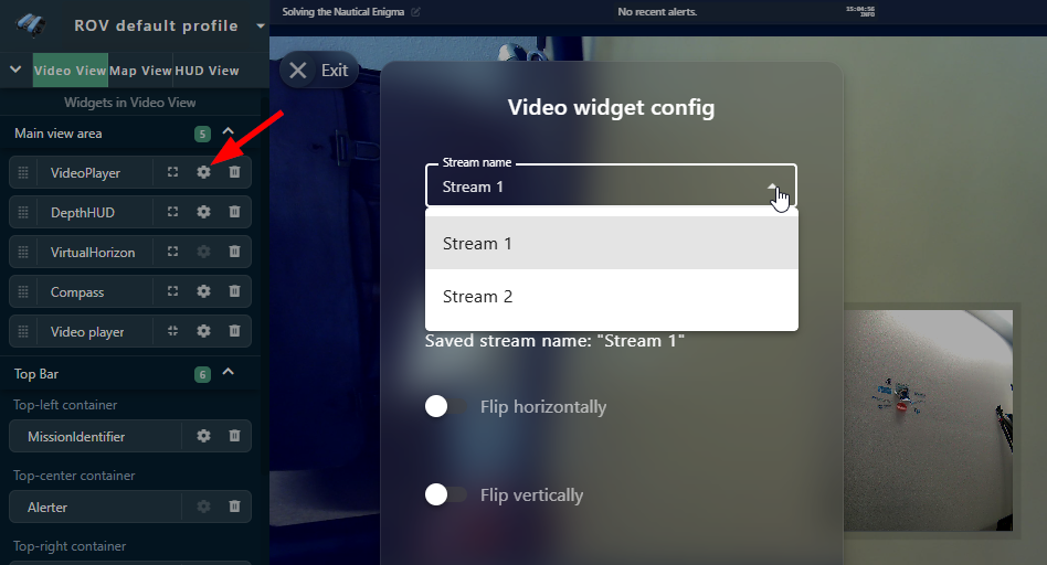
5. In Cockpit, open the main menu and go to Settings > Video. You should see the stream listed as madrona_cockpit.

6. Configure a video widget to display the stream.
Madrona also includes tools for taking snapshots manually or automatically at set intervals.

For more details on profile options, camera settings, and snapshots, check the Madrona documentation.
Reviewing and Measuring Images with C3 Review App
MarineSitu’s C3 Review App provides an interface to streamline the process of inspecting footage and sensor data from the C3 camera.
It can:
- Quickly navigate through recorded frames from one, two, or all three cameras, and visualize associated metadata.
- Tools to accurately measure and label objects, events, or regions of interest within your MarineSitu datasets.
Visit the documentation for installation and usage instructions.
Luxonis Software and Resources
The C3 camera is built around the Luxonis OAK-D W POE, so you can take advantage of existing Luxonis software, development tools, and AI models.
- Quick start with OAK Viewer application
- View Luxonis software documentation
Help and Feedback
- If you need help with this integration, reach out to our support team using our help center.
- If you have specific stereo data analysis questions or needs, you can contact MarineSitu directly.
- If you have any ideas on how we can improve this guide, let us know here.