
Building Subsea Cameras
By Tony White
This guide informs interested groups about the many design decisions and trade-offs involved in developing a subsea camera system. Blue Robotics does not currently offer a standalone subsea camera product, since the variety of possible applications makes a universal solution impractical. However, using modular, low-cost Blue Robotics components, it’s easier than you might expect to build a camera tailored to your specific needs.
Background
I’ve been using Blue Robotics components for marine robotics and aquaculture applications for over a decade, and subsea camera systems have been a recurring theme throughout that experience. The BlueROV2 often proves to be the most versatile and capable platform—it’s essentially an underwater camera with a controllable viewpoint. However, while flexible, it does have limitations such as battery life and depth rating. In many cases, a fixed-view camera can address a specific challenge more affordably and with more consistent performance.
Commercial options for standalone cabled cameras and drop cameras exist, but can be extremely expensive. However, it is quite easy to design and build your own, especially with the modular components Blue Robotics offers.
My first “camera on a cord” setup dates back to 2017, when it was used to monitor a hydraulic screw-anchor rig operating in 50 m of water near Los Angeles. It was paired with a BlueROV2 for broader situational awareness, but the fixed camera’s close-up view of the hydraulic motor proved invaluable for surface operators. That early system used an analog camera housed in a 2-inch Blue Robotics Enclosure—simple and inexpensive to build, but limited by poor image quality and no recording capability.
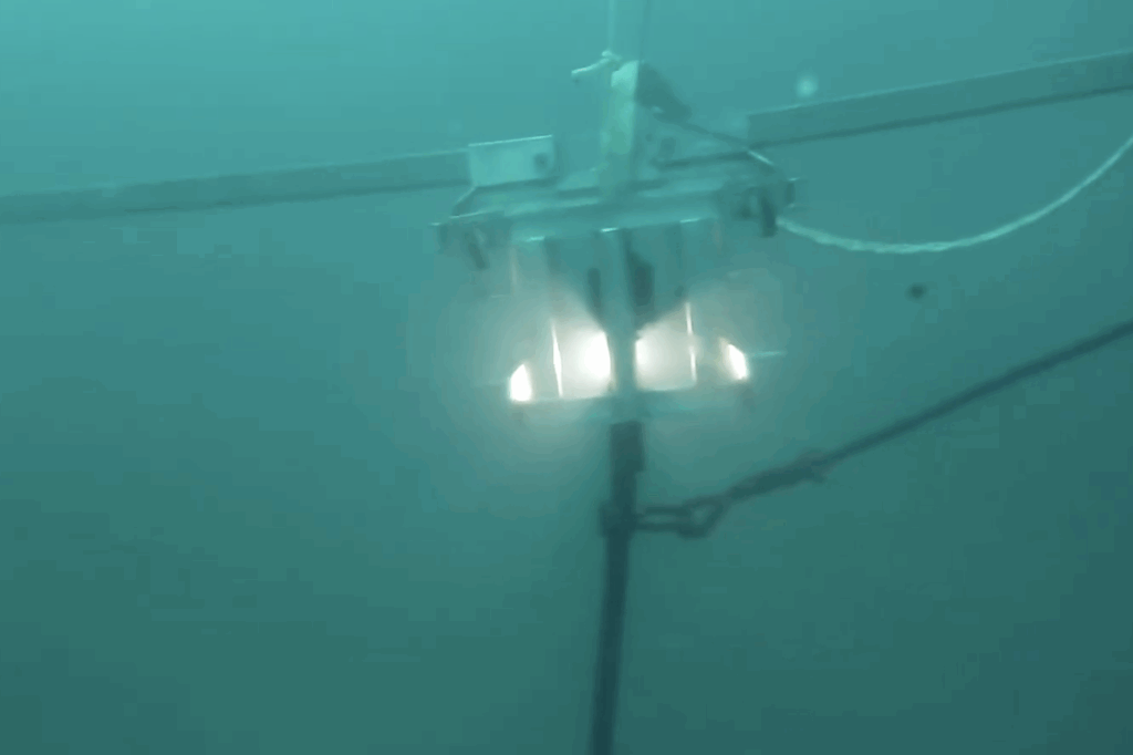
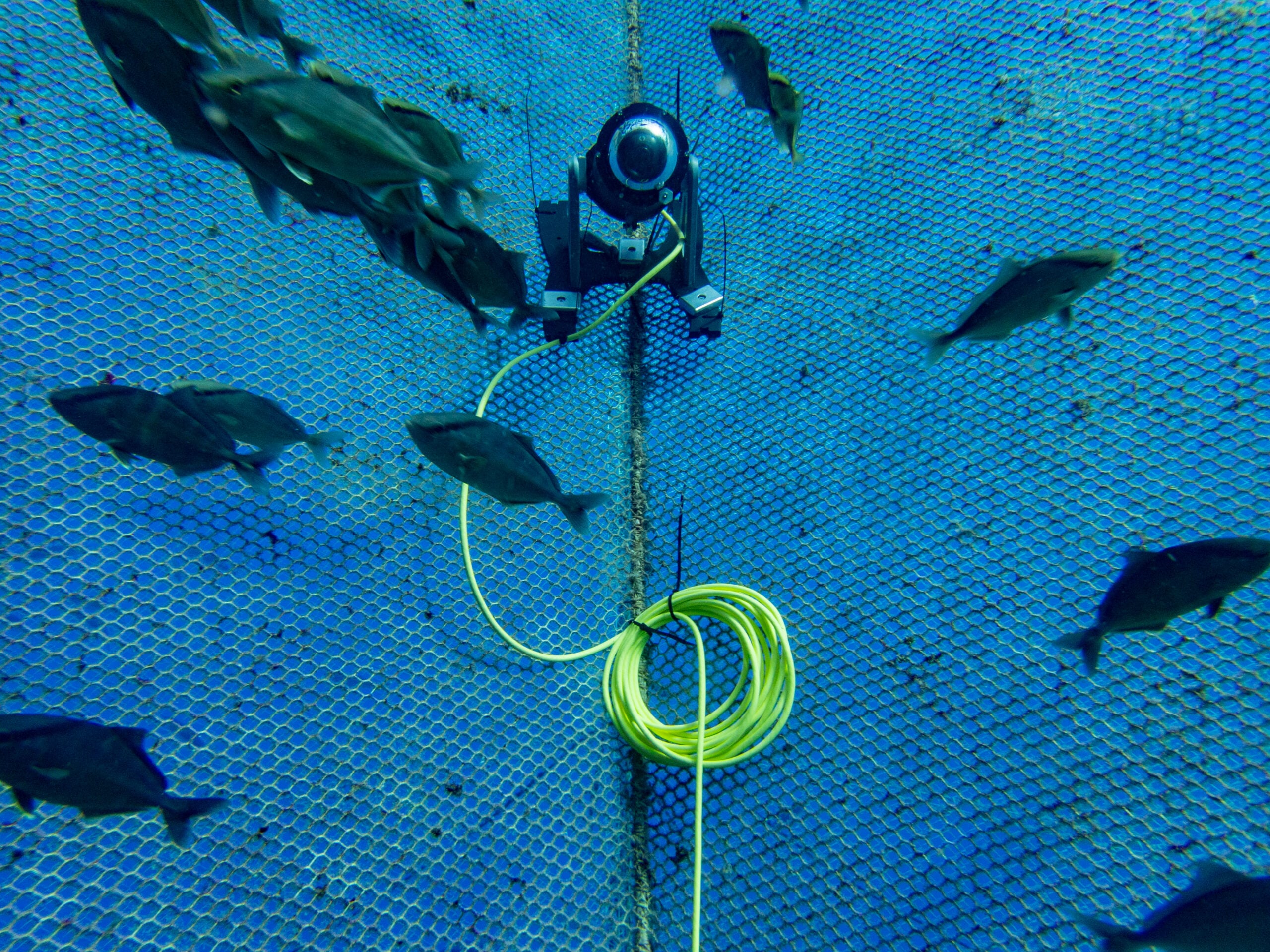
By 2019, working in Hawaii’s aquaculture industry, I began designing a digital subsea camera for remote fish monitoring in offshore net pens. A 3-inch Blue Robotics Enclosure housed a Raspberry Pi and a Low-Light HD USB camera, streaming video via proprietary software. Users could view live feeds globally, and a single tilt servo controlled the camera’s view, much like the BlueROV2.
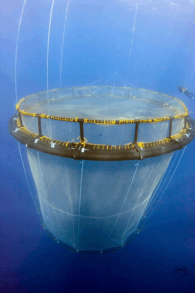
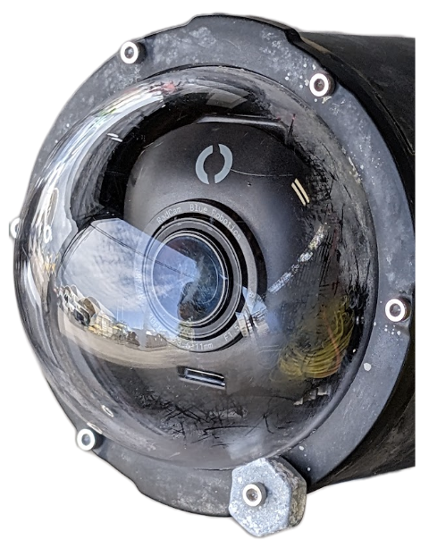
Fast forward to 2025: the latest system I’ve built uses a 4-inch Enclosure with a prototype Blue Robotics 4K IP camera called the RadCam. Unlike USB cameras, the RadCam sends video directly over Ethernet without needing a single-board computer. For testing purposes, I installed it in a Blue Ocean Mariculture fish pen off the coast of Kona. The system activates only when you retrieve the surface connector and connect it to a topside power/data source—also testing a prototype WetLink Connector. The 4K image quality is stunning! The system uses a modified BlueBoat BaseStation with a travel Wi-Fi router, Fathom-X interface, and a microcontroller inside the camera that manages servos through a web interface.
Types of Camera Systems
I like to divide subsea camera systems up into three general categories—live view, drop-camera, and a hybrid approach:
- A live view camera runs only when you connect it to surface hardware. Topside hardware records the stream to surface-based storage. Since the camera stream can be digital, it’s possible to have topside hardware stream the video to the internet – with settings you choose based on your livestreaming service.
- A drop-camera does not have an (electrical) cable going to the surface, and is battery powered. It records onboard, and may be setup to only record during certain hours of the day or when other conditions are met. Small battery powered action cameras excel at this, and affordable time-lapse cameras are also a great option when looking to build a camera with off-the-shelf components. A rope may be attached to these cameras for retrieval, or it will have to be hunted down at depth!.
- Finally, an approach that hybridizes the two types is a camera that is battery powered and records onboard, which supports live viewing when you connect it to the surface and also enables charging and video downloading via that link. This type of camera is the most complex, and has the most engineering tradeoffs to work through! Developing solutions for safely managing the (rapid) charging and balancing of a battery, and the management of the camera power/recording state would be required. However, once achieved, you could monitor an area continuously, without having to recover the camera to charge a battery, while still checking in on the view from the camera to confirm you’ve aimed the camera correctly. This is of particular interest in aquaculture applications.
| Camera Type | Live View Provided | Powered Over Tether | Records Onboard | Charges Battery Over Cable |
|---|---|---|---|---|
| Live View | Yes | Yes | No | No |
| Drop Cam | No | No | Yes | No |
| Hybrid Camera | Yes | Yes | Yes | Yes |
Design Reflections
Without a doubt, the biggest vulnerability of a subsea camera system is the cable or tether that connects it to the surface. Because radio waves don’t penetrate water, simply connecting via WiFi just isn’t possible!
- The tether is the primary point of failure for systems with one— the ocean will move it continuously, so if something pinches or pulls the tether, it may hold up for a while, but the ocean will eventually wear it down to the point of failure. Therefore properly routing your cable, and keeping it out of harm’s way is essential!
- Zip ties are the most common way to secure cables during installation, and, adding a “double-wrap” around your cable before securing it can prevent it from slipping when under tension. I prefer to use the reusable kind to cut down on waste and plastic in the ocean!
- Having a tether that uses connectors can also be critical for maintaining continuous operations. Simply swapping a tether, or repairing a tether connector on one end is a quick fix when a tether is damaged. Changing out a WetLink Penetrator can be a little more challenging, and isn’t possible to do without opening the enclosure.
- Another major challenge is biofouling—the tendency for the ocean to colonize any surface. You can prevent biofouling with special biocide paints, copper surfaces, or vaseline mixed with chili-powder, however none of those solutions are optically transparent. While not an issue for cameras that are only in the water for a short period, for deployments longer than 24–48 hours, plan to clean the optics either with a diver, a mechanically actuated wiper or brush, or even through the (short-duration) application of particular wavelengths of UV light! Often in mariculture the fish themselves take care of this duty, making contact with the camera frequently.
Notes on Typical Electrical Components
DCDC or ACDC power supply: Topside
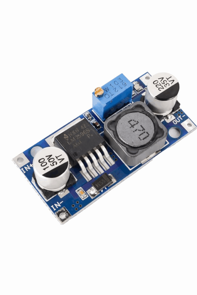
If you’re powering your system directly from a battery located topside, you’ll potentially want to increase the battery’s voltage to send power more efficiently down the tether to your camera. These regulators either output a fixed voltage, higher than supply, or have a small screw (typically on a blue block shaped component) that is used to trim the output voltage. In some cases, this output voltage remains dependent on the input voltage. These components are called “boost” or “step-up” voltage regulators. It’s important to note the power ratings for these components, keeping in mind they can produce quite a lot of heat, and may not actually achieve their claimed maximum power specifications…
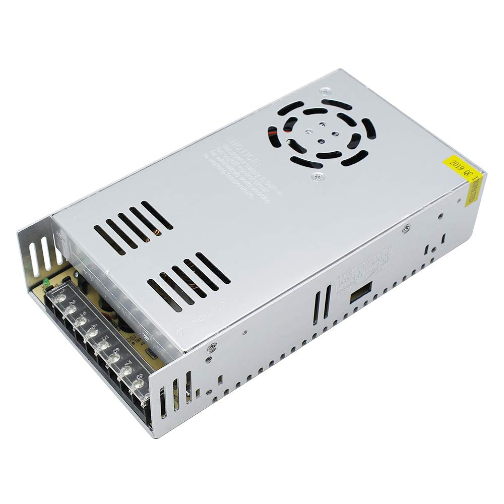
If you want to use a typical terrestrial power source, AC120V in the US, you’ll want a DC power supply that outputs a DC voltage from AC input—these are often also trimm-able, but across a smaller range (a few volts.)
DCDC power supply: Camera
You’ll likely need to step your tether supply voltage down to 12 or 5V DC, to power an IP camera or Pi and USB camera, respectively. When shopping for a DCDC supply, this means you’ll want a “buck” or “step-down” regulator.
Fathom-X
This or any PLC (power line communications) interface requires a small amount of power—in the case of the Fathom-X it needs 7–26V if powered from the screw terminals, or 5V when powered from the mini-USB jack. RAK wireless breakouts for the LX200V30 and V50 require 12V DC. This technology was developed to send ethernet signals around a home or building’s existing electrical wiring.
Raspberry Pi SBC (single board computer)
This is ordinarily the most power-hungry component in a camera enclosure—using anywhere from 3–10 watts depending on the CPU load and model. It’s important to have a 5V DC supply that can supply at least 3 amps for reliable performance!
Microcontrollers
Many ESP32 and PiPico microcontroller boards breakout an Ethernet interface. When you need to generate a control signal and have a web interface, but don’t need the CPU to be involved in video streaming, using a microcontroller is the most power efficient option. I used a PiPico with an IP camera to control servos connected to a camera’s vertical tilt, focus and zoom motors. This was a compact way of providing that control of the camera tested at Blue Ocean Mariculture—you can find the source code for that here.
Ethernet switch
An ethernet switch isn’t required unless you have more than one ethernet device in your camera enclosure. So a SBC + USB camera + Fathom-X doesn’t need one, but an IP Camera + Fathom-X + Microcontroller (with ethernet) would! When connecting payloads that communicate over ethernet, like some sonars or hydrophones, a switch would also be required. The Blue Robotics Ethernet switch is quite compact, and has a very wide input voltage range of 5–52V!
Servos
Whether used inside the camera to control tilt, pan, focus or zoom, or outside the enclosure to control tilt, pan or a wiper, servo motors can consume a significant amount of power. Miniature servos may use a few watts, but a subsea servo can use an order of magnitude more power, depending on the load! Because motors are an inductive load, the current that rushes into them when a motion is triggered can cause the local voltage to drop low enough to cause issues with other electronics, even if it only happens for a fraction of a second.
Capacitors
Including a large capacitor (like this general type of supercap) in your camera can help ensure high power, short-term loads (like a servo) don’t cause issues! Make sure the capacitor’s rated voltage is significantly higher than the voltages you’ll be exposing it to. The larger the capacity, the better it can filter out the voltage drops from large power spikes.
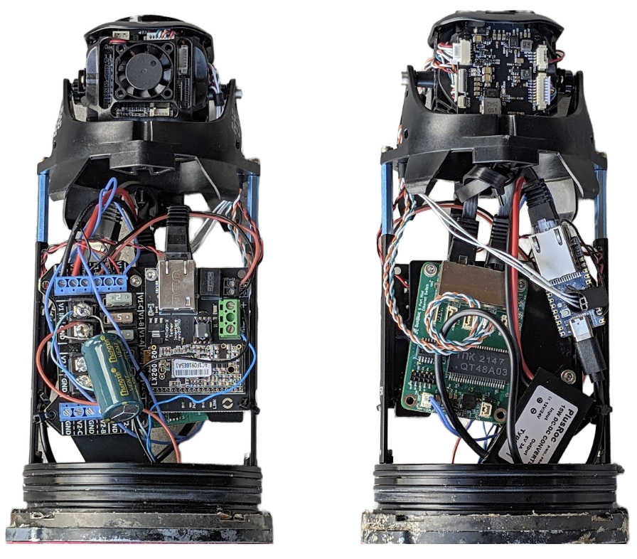
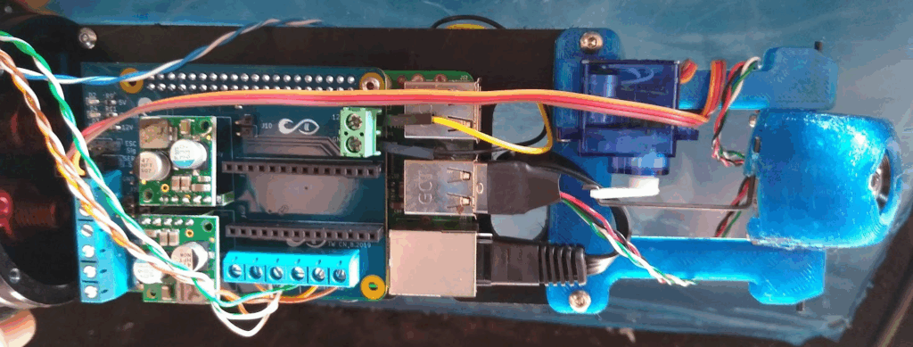
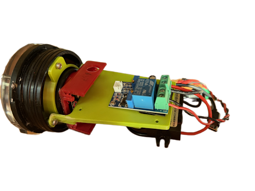
Live-view camera with RadCam, BlueBoat Fuse board, Fathom-X, Ethernet Switch, RP2350, and 5V DCDC USB-C power supply mounted on RAILS in 4” Blue Robotics Enclosure.
Sending Power
If you connect a 12V DC power supply to one end of a long tether, and measure the voltage at the other end, it may be very close to 12V — until you start to pull power! Ohm’s law tells us the voltage will drop, as power is dissipated in the long wire length that is acting like a resistor. This Blue Robotics calculator is a critical tool when designing your system! With it, you can specify the tether length, and the number and size of conductors you intend to use to send electrical current. The amount of power you will need at the load depends on the camera and your payloads, but is often around 10 watts. Using that in this example, we can see what DC voltage you need on the topside to provide sufficient power without excessive cable losses!
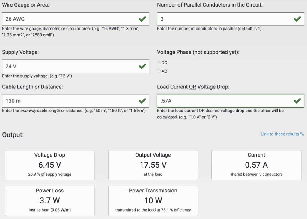
In this example, we send 10 watts down a Fathom tether’s 26AWG wires, using 3 conductors for positive and 3 for negative (leaving just 2/8 to send data.) As the load current increases, the power transmission does as well, until the resistance of the cable causes too much loss:

At almost 3x the current flow, we’re losing almost 8x more power to heat in the tether, and our efficiency has dropped almost 50%. The power at the load at a given wire length and size is inherently limited! Increasing the supply voltage at the topside is the best way to send more power and have less loss, however above 24V damage to the cable can result in risk to nearby swimmers or fish, and above 48V DC can start to be hazardous!
It’s generally safest to try and keep your topside DC supply below 30V. Adjustable DCDC converters are great in this application, as they can be trimmed to output a voltage sufficient for your camera’s load! It’s also good to avoid being less than 50% efficient, or having more than 5–10 watts lost as heat on the tether, especially when large portions of that cable won’t be cooled by water!
Sending Data
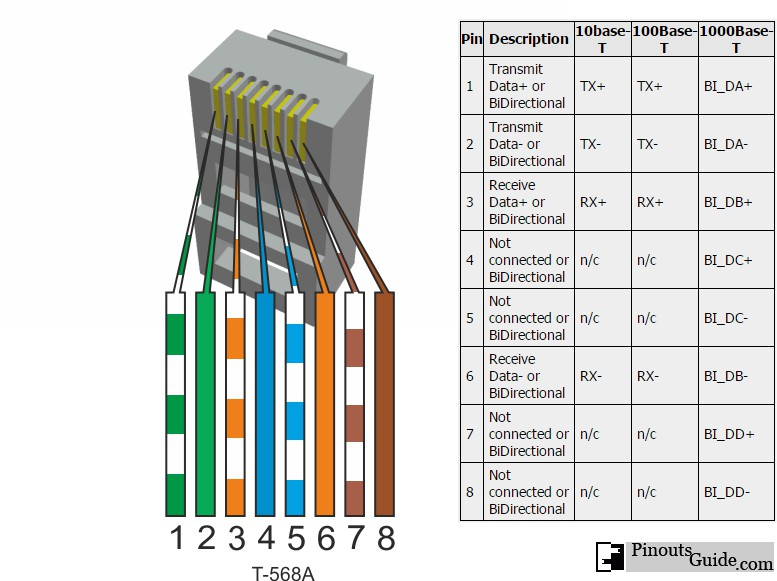
For short cables, less than 50 m, it’s likely possible to use standard Fathom tether as Ethernet cable, even though it doesn’t meet the Cat5/Cat6 specifications. You’d use two twisted pairs, typically orange and blue, to carry standard ethernet traffic (pin 1,2,3 and 6), and the remaining 4 wires to carry power. This is commonly known as passive power-over-ethernet (POE.)
You could, of course, use standard ethernet cable, but that is likely to be less robust in the marine environment. Cable that does meet Cat5/Cat6 specifications can be used for up to 100 m, but in reality the limit is more often closer to 70–80 m depending on the quality of the cable and the network hardware used with it.
- To connect over a longer distance, or to free up a twisted pair to send power with, the Fathom-X tether communications module uses PLC (power-line communication) modules to send TCP/IP data over a single twisted pair! These black-magic device uses LX200V20 chips to communicate at higher frequencies and with a different protocol than Ethernet, providing a link on up to 300 m of Fathom tether or 200 m of Fathom slim tether—only one twisted pair is required!
- In cases where the power draw is minimal and not particularly noisy, you can actually send power and data over the same wires! It’s best to assume you won’t be able to mix power and data, and only take this approach if you need more copper to send power with, as the noise generated by a load may increase as the tether length increases, and impact stability of the communication link.
- Other breakout boards for the LX200 series exist, including the V30 and V50—these can provide higher bandwidth over similar tether lengths, and even enable longer lengths.
- To maximize range and bandwidth, there’s no substitute for light moved through tubes—fiber optics! This type of tether is inherently a bit more fragile, and if kinked sharply can break the fiber, killing communications. Fiber termination also takes time and specialized tools. The light signals are converted back to TCP/IP over copper via media converters or SFP interfaces. We haven’t worked much with fiber-optic communications, but there are good resources out there!
Thinking Through Your Build
As with any development project, making a detailed plan before you start assembling things is key to success. With that said, having the components in hand and playing with their arrangement physically can often reduce the number of iterations required to develop your packaging solutions. The following steps cover things to keep in mind.
- The requirement that drives your overall subsea camera design the most fundamentally is the length of the cable you intend to use with it! Since you’re likely powering the camera from the surface, you need to account for power loss due to resistance along the cable. Additionally, to send digital data down long wires can require some consideration of cable and signal type. So the cable length will dictate what the required tether voltage will be, to send sufficient power to run the camera, as well as what method of communication will be used to send the digital video data down the tether.
- Ask yourself—how does the camera need to be oriented? How is it being installed? What do you need to to do to hold the camera enclosure stable at the desired angle, and can this be enhanced passively with buoyancy? With a clear idea of how your camera will be used, deployed, recovered, and oriented, you can plan what size enclosure you’ll use, and how you’ll mount each electrical component. This may involve clamps, 3D printed brackets, or even external servo motors. The camera lens should be mounted within your tube so it is located precisely at the spherical center of the dome—this makes focusing the camera as straightforward as possible. If the camera needs to tilt up and down from there, the impacts on focus are minimal enough to ignore.
- With the enclosure selected, it’s time to work on assembling its internals with RAILS or whatever mounting hardware scheme you invent, determining how your electrical components will be secured in relation to the dome in a natural design progression. You’ll want your internal structure to all be attached to one endcap, and the tube with dome fits over this frame structure. Otherwise, if things are mounted to the dome side, the electrical connections to the opposite endcap with cable penetrations have to have sufficient length to open the enclosure, leading to frequent reconnections of the internal cables. This can lead to premature failure as some connectors are not rated for infinite cycles! The endcap plate opposite the camera end of the enclosure is where your data and power tether cable enters, and has additional holes for other accessories like lights, pressure sensors, actuators, or whatever else you may think of. A vent plug is always good to include as it enables vacuum testing.
- Once your electronics are mounted, it’s time to wire them together. I like to start with power, routing from the tether connection to components that take tether voltage like motors and DCDC power supplies. Then, power connections to any SBC and cameras are made. USB cameras use only one connector for power and data! I don’t include fuses in a system like this—the long tether acts to restrict high current flow in the event of a dead short, and the low voltage / lower power components in use won’t trip a fuse if a leak should occur—it turns out saltwater isn’t a good enough conductor to make most fuses pop!
- With all your power and data connections are made, with the enclosure open, it’s time to double check polarity for all DC power connections. This is good to do before connecting power to prevent accidentally releasing any magic smoke from components without reverse-polarity protection! Check to make sure power and ground are not shorted is also a good sanity check. When you connect power, verify that all the expected LEDs turn on, and after your camera or SBC has started up, get connected over the network!
- Finally, with things confirmed as functional, it’s time to remove power and assemble the components into the enclosure. I like to run the hardware on the bench sealed up for at least an hour or two, to verify that heat transfer in the worst case (no external water cooling) doesn’t cause any issues. Before getting the system wet, it’s a good idea to do a vacuum test—of course with no air heat transfer gets even worse, so make sure to remove power before doing so! With confidence that your electronics are stable and housed in a leak-tight housing, it’s time to get things in the water!
Viewing Video On the Surface
Simple Analog
An analog video monitor commonly runs off of 12V, and works well in automotive applications like back-up cameras. Besides affordability, a topside for an analog camera system is certainly the simplest and fastest to start up! A battery or 12V power supply is connected to the monitor, alongside the single wire carrying the camera’s analog signal—video. Video is then displayed, albeit grainy, low resolution, and not easily possible to record. Many legacy cameras use analog video even in the modern world!
Digital Video
To open a digital video stream, you’re going to need a computer of some kind. Laptops, or desktops paired with a battery power supply and sunlight readable monitor are the typical solution. Media players that can open RTSP streams work with any operating system and processor architecture, like VLC media player. Depending on your tether communications method, you’ll need hardware to supply the correct voltage to your tether communications interface at the topside. You’ll also need a power source that can provide DC voltage at the level required by your tether length. It’s critical that this hardware is protected from the elements! A good briefcase style enclosure can hold a laptop and other required electronics in a safe manner for use and transport.
Viewing Digital Video with VLC Media Player
If your IP camera is producing a RTSP stream, it has a url that is something like “rtsp://192.168.2.10:554/stream_0”. To view it, open the free and open source media player, VLC, and go to file > open network stream (control/command + n), you can enter in this stream URL and push open to view. Record by checking the box for stream output, and under settings select a location to save your recording. Depending on the video format, you may need to enter a different file extension to correctly save the video. When you click open, the stream will play on your computer while simultaneously recording to file. USB cameras in BlueOS can be configured to output UDP video, or RTSP— the latter can have lower latency with VLC, and simply copying the URL from the Video Streams page to VLC is all the setup required!
Camera Operation tips
- Using DCDC power supplies with digital displays can make trimming the output voltage easier, but they consume slightly more energy. A multimeter serves as the display for power supplies without one during this setup step.
- When using the Fathom-X or other PLC modules based on the LX200v30 or v50, a “link light” or confirmation of connection is required for TCP/IP packets to be successfully routed over the tether.
- A Pi usually takes a couple minutes to start up when power is applied—if you need video quickly, consider an IP camera, or just be patient!
- BlueOS has a Tether Diagnostic extension that communicates directly with LX200 modules, providing feedback on the quality of the connection—check out the documentation here.
Live-View Cam Specific Advisements
To transmit digital video along our network cable, it needs to be sent as TCP or UDP packets. A USB camera doesn’t output this format or have this interface, so a CPU is required to stream the video from the USB interface across to the ethernet interface. IP cameras have more powerful CPUs onboard that can create the necessary format video packets directly, without requiring external hardware or software—however, the features and security of IP camera software interfaces vary wildly between vendors, and finding a part you can buy consistently and in the long term, while also being affordable, can be very challenging.
Generally, when looking at IP cameras that support BlueOS or as wide a variety of systems as possible, look for H264 video output, and RTSP / ONVIF support. These features will let devices find it on the network easily, and control it via standard protocols. This camera is a good example of something that may work well, at least from a supported features perspective. As you review the documentation, note that it requires 12V DC, and has a separate port for an ethernet connection. Figuring out the default IP address and login credentials can be a bit of an adventure, depending on what documentation is included!
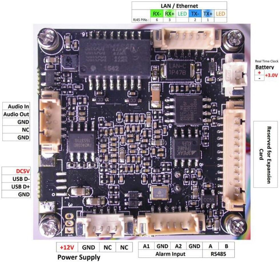
A typical IP camera has Power (12V in this case) and standard Ethernet connection, and usually includes cables that connect to the PCB that can be spliced into your system
Analog cameras are not covered in depth in this guide, but they are worth mentioning for comparison. Analog video systems output a low-resolution image over a single signal wire, accompanied by power and ground connections. They are simple and inexpensive—automotive backup cameras and older security cameras often use this format—but the image quality is poor, and interference from electrical noise or voltage drops can easily degrade the signal.
A dedicated monitor usually displays analog video with a composite (RCA) input, recognizable as the yellow connector once common on VCRs and early televisions. While these systems are easy to power and deploy, they are increasingly outdated and difficult to record or integrate with modern digital systems.
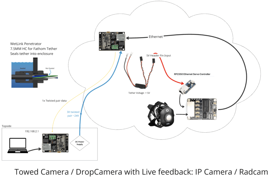
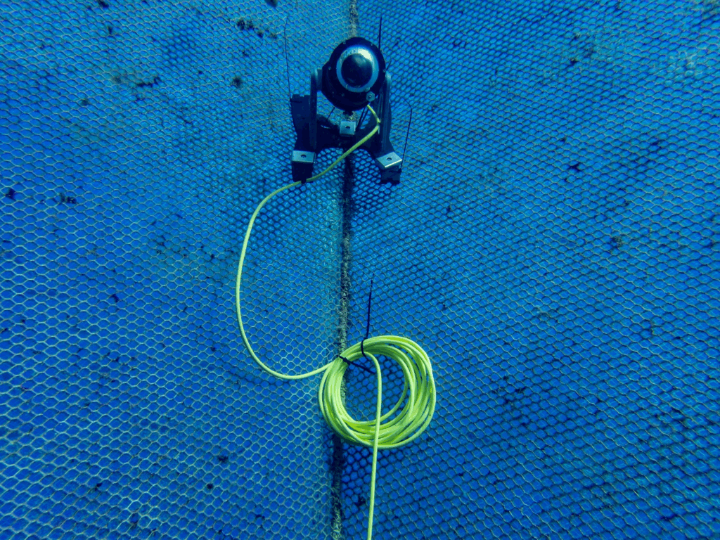
Live-view IP camera using Fathom tether. Maximum theoretical tether length based on 9W power draw, 36V topside, Fathom-X length limitation: 300m
This guide presents guidance for both USB and IP camera approaches, but these latter instructions stay somewhat vague when it comes to configuration, so keep that in mind when choosing your approach.
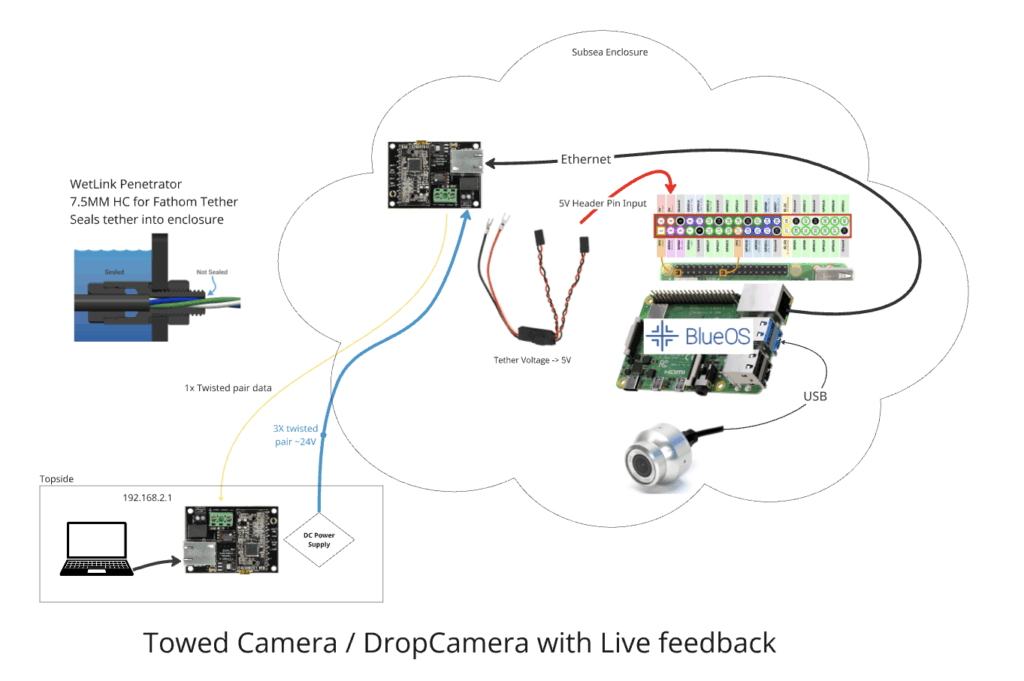
Live-view Pi-powered USB camera using Fathom tether. Maximum theoretical tether length based on Fathom-X length limitation: 300m
If you’d like to develop software that does something interesting with the incoming video, especially if you’d like to run this software “on the edge,” a USB camera is a good choice. The Raspberry Pi software ecosystem is extensive, although the hardware has somewhat limited capacity when it comes to applying OpenCV or other intensive software libraries for machine vision applications, like encoding video with overlays. A Nvidia single board computer like a Jetson can be considerably more powerful, but may require a larger enclosure like a watertight box. The Pi Zero can run BlueOS in an incredibly small footprint, and has just enough capacity to re-stream an unmodified H264 video to the surface. Thus, the size of the enclosure is driven by both the camera and SBC size! When using an external USB camera like the exploreHD, the enclosure only needs to fit your supporting electronics and have sufficient holes for the tether and camera payload(s)- no transparency necessary. Setting up a Pi with BlueOS will make getting your live-video stream setup a cinch, with no Navigator autopilot required. Connected (and supported) cameras show up on the Video Streams page. If you want to record video onboard the Pi, this is also possible with a bit of DIY software or the DashCam extension.
Drop Cam Specific Considerations
When considering an untethered, battery powered camera:
- For short deployments, you’ll want to select an off the shelf “action” style camera like GoPro, DJI, and Insta360 sell.
- Some vendors also make lower cost cameras, aimed at folks looking to take timelapse video. What you lose in image quality may be worth it when considering battery life, and the ability to configure recording on a schedule.
- Recording the darkness of night isn’t typically very useful! GoPros can be convenient with newer models supporting advanced timing configuration via QR code.
- To fit in a 2” or 3” cylindrical enclosure, you may need to partially disassembly the camera — the lens and sensor module are often connected via ribbon cabe to the main camera circuit board. Again, positioning the lens of the camera in the dome is critical to get an in-focus image! If you’re facing focus issues, a flat clear endcap can also work, but may introduce distortion to the image.
- If you only intend to record for an hour or two, the camera’s built-in battery is likely sufficient. Otherwise, you’ll need to make sure your enclosure has room for the USB power connection to the camera, or directly solder wires on at the appropriate location to provide external power.
- A 4S 18Ah Blue Robotics battery holds ~265 watt hours, which is about 66x more than a typical 4 watt hour GoPro battery! You’ll want a DCDC converter to step the battery voltage down to 5V—this is a case where a module like this that provides the output via USB connector is quite convenient!
Once you’ve mounted your camera, battery, and power electronics in an enclosure, you’ll want to take some test recordings to verify focus. To maximize your recording time without over-discharging and damaging your battery, it’s critical that you use a low voltage cutoff. Units like this can be set up to disconnect the battery from the camera when it drops below 12V, and preserve the battery for future use. If you don’t take this step, and the battery is over-discharged, it will be permanently damaged, either no longer taking a charge or holding significantly less capacity!
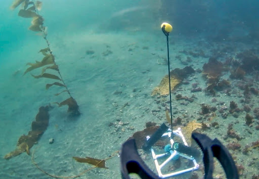
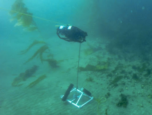
Using a camera like this conventionally consists of opening the housing to connect the battery, and turn on the camera, starting it recording just before deployment. It’s often best to attach the camera housing to some sort of frame, to help it land on the seafloor or be attached to whatever target location. In most applications, the hardware is retrieved many days later!
Here is an example of a camera fit into a 3” housing (with a bit of trimming) and powered with a Blue Robotics battery—it recorded an image every 10 seconds for over 2 weeks, during daylight hours. This was a fun Blue Tech Academy module!
You’ve made it this far into the guide, which makes us think you might actually be considering building a camera system of your own! Enjoy 20% off our Watertight Enclosures with the GUIDEREADER coupon code!
Hybrid Cam Musings
Making a camera that provides both a live-view when connected, and continues to record when not involves a few more requirements.
- The tether now needs to be used not just for data delivery, but to route power, at higher levels than the system consumed in order to charge an onboard battery. Depending on the power consumption of the camera, and the frequency and duration of planned charging cycles, this may mean significant power needs to be sent down the tether!
- Charging batteries in an enclosure is inherently dangerous, because when done improperly, the lithium-ion batteries can expand, vent, or explode – all bad things to do in a confined space! It’s important to prevent over-voltage and under-voltage conditions on the battery, and critically, a proper charger must balance each set of parallel cells in the pack. See the Blue Robotics battery care guide for more information.
- A microcontroller using a real-time clock to control a low-power solid-state switch can manage the power status of the camera and associated hardware. This microcontroller controls on/off timing based on the day/night schedule, or whatever the application requires. It can also have awareness of the battery voltage, to keep things off if it is too depleted to support operation.
- When external power is connected, it may make sense to automatically turn on the system, and communicate information on the battery and charging to the surface interface.
- Finally, managing the collected recordings is important. Should they stop when the available memory is full, or continue, deleting the oldest recordings? Software that makes downloading saved videos and clearing memory via the tether network connection seems particularly useful.
Conclusion
Designing a subsea camera system is an exercise in balancing simplicity, performance, and reliability against the relentless forces of the ocean. Whether you’re building a live-view tethered unit, a self-contained drop camera, or a hybrid system that does both, success comes down to understanding how power, communication, and mechanical design interact under pressure and over large distances.
Blue Robotics’ modular ecosystem makes it possible to build highly capable systems without the cost and complexity of custom manufacturing. By carefully planning your tether length, voltage, data interface, and housing configuration, you can develop a camera system that fits your exact needs—whether that’s long-term biological monitoring, industrial inspection, or creative exploration.
Every subsea deployment teaches something new: how to route cables more securely, manage heat dissipation more efficiently, or keep the optics clear longer. Sharing your project with the community is a great way to review your design, and motivate development. With thoughtful design and a willingness to iterate, you’ll find that creating a robust underwater camera system is not only achievable—but deeply rewarding.
Authors

Tony White
Tony White earned his Mechanical Engineering degree from Georgia Tech in 2012 and began his career with large autonomous hydrographic survey vessels with C&C Technologies (Louisiana) and ASV Ltd. (England). He later moved to Los Angeles to join Ocean Lab, where he helped design and deploy a swarm of 50 marine surface drones—the “Data Diver”—his first major project using Blue Robotics components. After some aquaculture experience in Los Angeles, he went on to Forever Oceans in Hawaii (and Panama), where he developed innovative camera monitoring systems and resident BlueROV2 platforms for remote fish mortality extraction. Since 2023, Tony works in Blue Robotics’ Product Experience and R&D departments, where he assists customers with applications and tests both in-house and third-party products, the latter evaluated for potential resale on the Blue Robotics “Reef.”