BlueBoat Operator’s Guide
So you’ve finished assembling your BlueBoat and have it connected to your computer, now time to send it out on its first mission! This guide will walk you through the essentials of operating your BlueBoat, including:
- Connecting and charging batteries
- Loading payload
- Mission planning
- Setting up for and conducting a mission
Your BlueBoat must be fully assembled and the software must be set up before you operate. If you have not assembled your BlueBoat, please see the BlueBoat Assembly guide. If you have not completed the software setup, see the BlueBoat Software Setup guide.
The Basics
The following is some basic information to familiarize yourself with the BlueBoat and BaseStation.
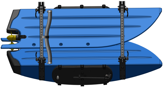
The BlueBoat
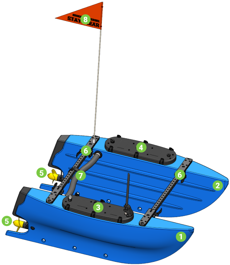
| # | Component |
|---|---|
| 1 | Starboard Hull |
| 2 | Port Hull |
| 3 | Starboard Hatch Lid Assembly |
| 4 | Port Hatch Lid Assembly |
| 5 | M200 Motor (BlueBoat variant) + Weedless Propeller |
| 6 | Frame |
| 7 | Crosstube and Cross Cable |
| 8 | BlueBoat Flag |
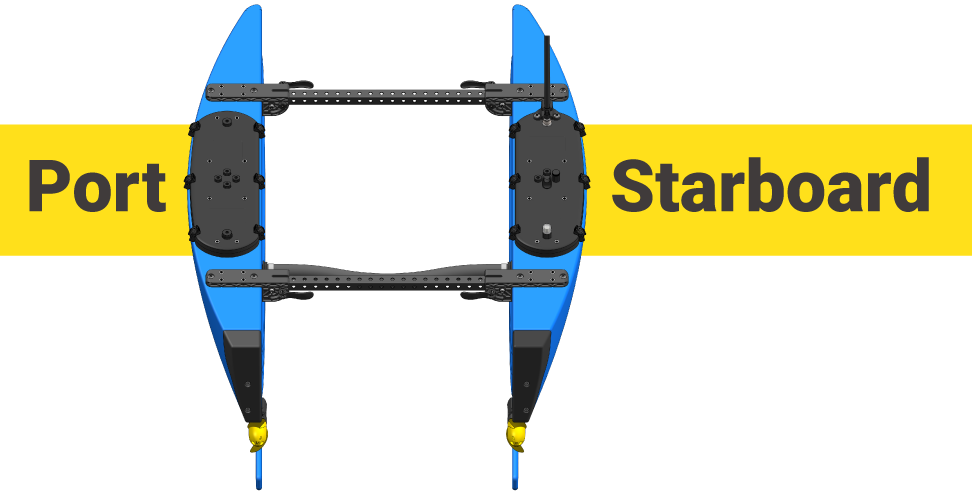
Port and Starboard
In this guide and other BlueBoat guides, we will refer to the left side and right sides of the boat using the nautical terms “port” and “starboard”. If you imagine you are on the BlueBoat, facing the front of the boat, the left side is the port side and the right is the starboard side.
Starboard Hatch Lid
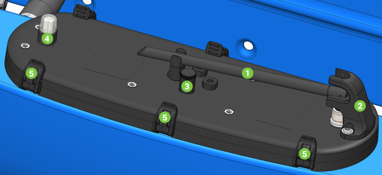
| # | Component |
|---|---|
| 1 | Antenna |
| 2 | Antenna Guard |
| 3 | Penetrator Switch |
| 4 | NavLight |
| 5 | Latches |
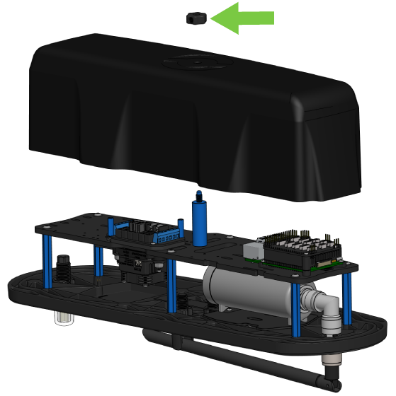
Starboard Electronics Tray
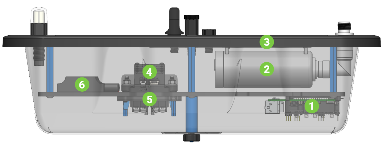
| # | Component |
|---|---|
| 1 | Navigator Flight Controller + Raspberry Pi 4 |
| 2 | RBGroove-52HPn Wireless Router |
| 3 | mRobotics M10034-M9N GPS |
| 4 | PowerSwitch |
| 5 | Fuse Board |
| 6 | Blue Robotics Basic ESC 500 (BlueBoat variant) |
Folding and Unfolding the BlueBoat
The BlueBoat hulls can be folded in to make transport easier.
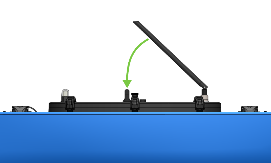
1. Fold the antenna down into the antenna clip.
2. Unlock the clamp levers.
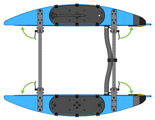
3. Fold the hulls inward one at a time.
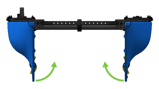
Lock the clamp levers again then the BlueBoat is ready for transport. Reverse the directions to unfold the boat.
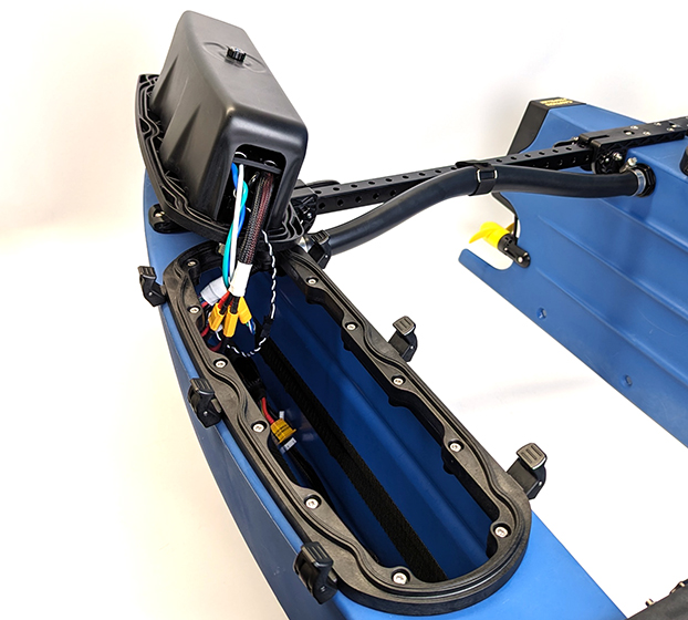
Opening the Hatches
Open the hatch lids by pressing in the latch clips to release the latches.
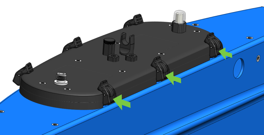
Releasing the latches.
To access the electronics trays, remove the hatch lid clamshell (cover) by unscrewing the thumb nut.
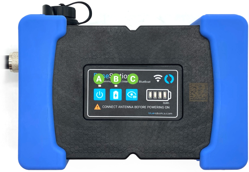
The BaseStation
The BaseStation is the Wi-Fi radio access point to connect your computer to the BlueBoat.
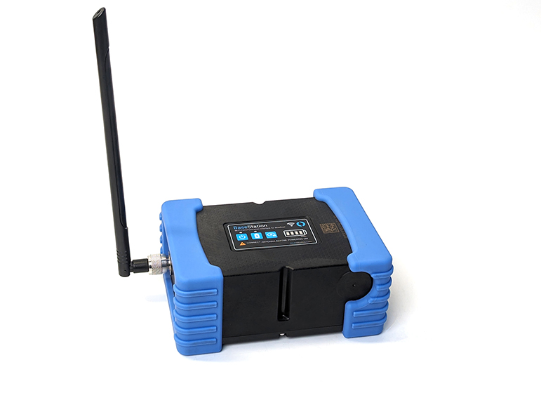
Use the buttons on the control pad to power on and charge the BaseStation. Press and hold the power button (A) for 2 seconds and release to turn the BaseStation on and off. Press the charge (B) button to toggle charging on and off. Press the charge status button (C) to show the internal battery charge status.
Charging the BaseStation
1. Unscrew the cover off the USB-C bulkhead connector.
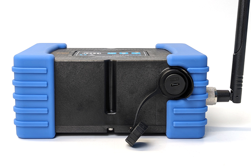
2. Use the included USB-C cable to connect the BaseStation to a USB power source. This could be a USB port on your computer, a USB wall charger, a USB power bank, etc.
3. Press the charging button on the BaseStation panel to begin charging. The orange indicator LED above the charging button and the battery status LEDs should light up to show that the battery is charging.
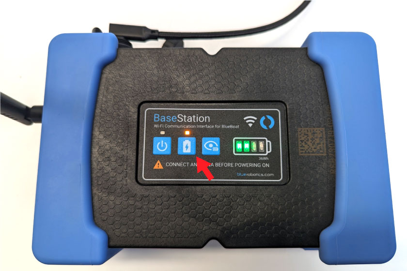
4. The orange indicator LED above the charging button will turn off when charging is complete.
Connecting Batteries
The BlueBoat supports connecting up to eight Blue Robotics 4S batteries (four in each hull). There is a battery connection cable, referred to as a 4S splitter cable, in each hull. The 4S splitter cable uses male XT90 connectors for the battery connection and 5-position JST XH connectors for the battery balance leads. The BlueBoat supports all Blue Robotics 4S lithium batteries.
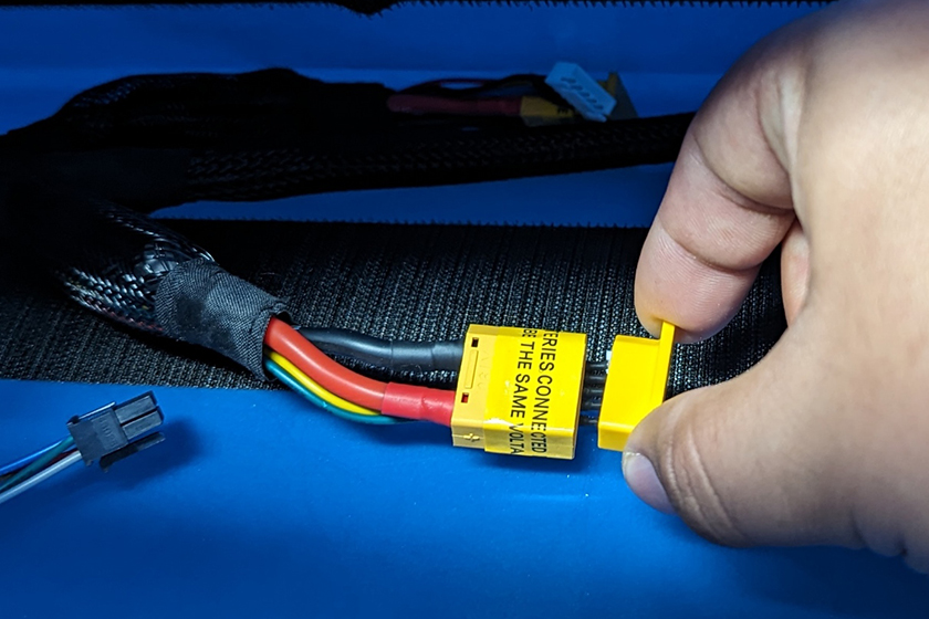
Connecting Batteries in Parallel
The battery connections in the BlueBoat are all electrically connected in parallel. Connecting lithium batteries in parallel requires extra precautions to avoid damaging the batteries and equipment:
- Only connect batteries with the same specifications in terms of voltage, amp hour capacity, and discharge rate.
- Only connect batteries that are at the same charge level (voltage), within 0.2 volts.
- Only connect batteries that are similar in age and health.
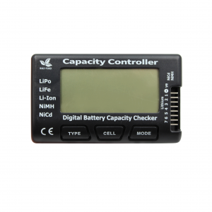
The Battery Cell Checker can be used to quickly check a battery’s charge level (voltage) before connecting.
To connect the batteries:
1. Open the hatch lid to access the inside of the hull.
2. Remove the connector caps from the XT90 connectors that will be used to connect a battery, while leaving the caps on any unused connectors. The connector caps should always be installed on any unused XT90 connector to prevent electrical shorts. Be sure to save the connector caps for use later.
3. Connect the XT90 and balance lead connectors from the batteries to the 4S splitter cable. The splitter cable should always run underneath the batteries to minimize electromagnetic interference with other electronics.
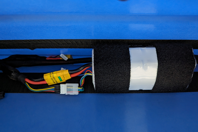
4. All batteries must use Velcro strips to secure them in the hulls. Unsecured batteries may become disconnected during operation, leading to electrical shorts or complete loss of power.
5. Close the hatch lid and lock all of the latches by pushing each latch in from the top until it snaps into place.
Charging Batteries
Batteries can be disconnected from the BlueBoat and charged normally, or they can be charged in parallel while they are connected inside the BlueBoat.
For long-term storage, or when the BlueBoat will not be used for a few days, batteries should be removed from the hulls and charged or stored according to their usage guidelines. If you are using Blue Robotics batteries, you can find the charging and safety information for each type of battery here. Instructions for using the Blue Robotics H6 PRO charger can be found here.
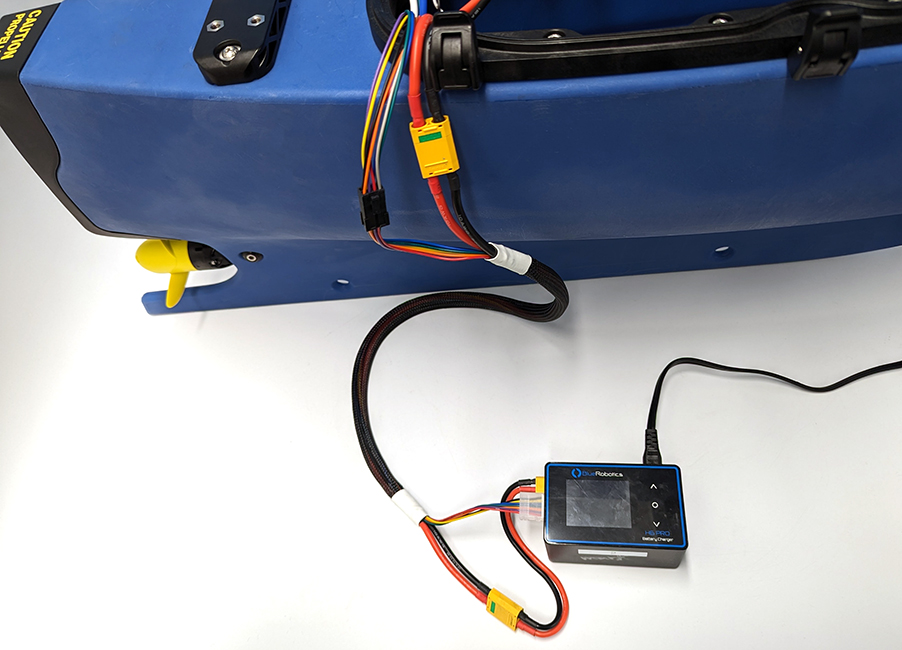
Batteries can also be charged in parallel while they are connected inside the BlueBoat for immediate use. To charge the batteries in parallel:
1. Open the starboard side hatch.
2. Disconnect the cross cable XT90 connector from the “STBD PWR” cable.
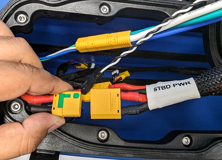
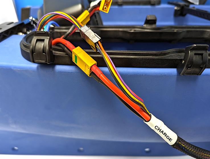
3. The BlueBoat kit includes an extra cable labeled “CHARGE”. Connect the XT90 connector from this charging cable to the XT90 connector you just disconnected. Connect the 8-position Molex connector from the charging cable to the free 8-position connector from the cross cable.
4. Connect the XT90 connector and balance connector at the other end of the charging cable to the charger and charge normally. If you are using Blue Robotics batteries and a Blue Robotics H6 PRO charger, please review the battery charging information and H6 PRO charging instructions.
Loading Batteries and Payload
The BlueBoat has a total payload capacity of 15 kg (33 lbs), which includes the capacity for batteries and any additional payload. The weight distribution of batteries and other payloads directly affects the stability of the BlueBoat. An imbalanced load may cause the boat to lean to one side, or become unstable and prone to tipping. Maintaining proper weight distribution is essential for stability, maneuverability, and efficient operation on the water.
Follow these guidelines to ensure proper weight distribution:
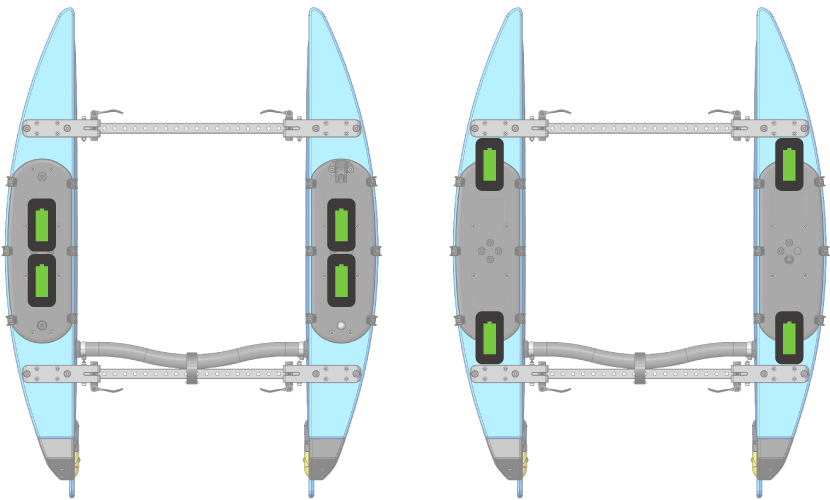
- Evenly distribute the batteries between the hulls whenever possible. For example, if you are using two batteries in total, load one battery in each hull.
- Load batteries within the hulls so their weight is evenly distributed from front to back. For example, if there are two batteries in a hull, place both batteries in the center of the hull or place one in the front and one in the back.
- Payload should be loaded or mounted to the BlueBoat so it is balanced whenever possible. If a payload cannot be evenly balanced, the batteries can be loaded such that they counterbalance the uneven payload.
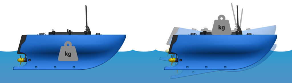
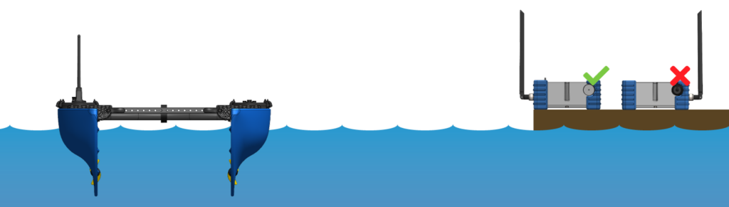
- Try to mount payload as low as possible. The BlueBoat is inherently more stable with lower-mounted payloads, as higher mounted weight can lead to increased pitching instability.
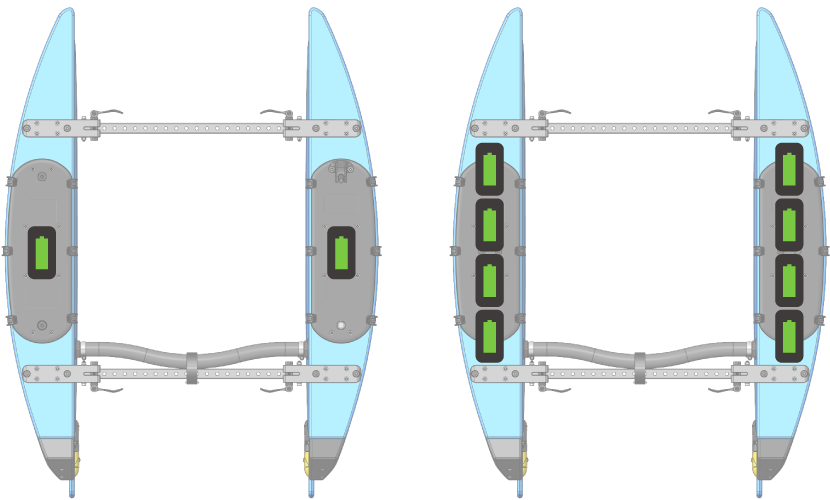
Examples of loading two or eight batteries.
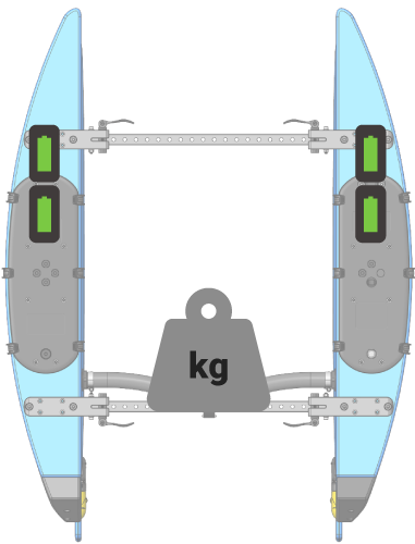
In this example, the batteries are loaded in the front of the hulls to counterbalance the heavy payload in the back.
More information about payload mounting features and electrically connecting payloads is available in the BlueBoat General Integration Guide.
Setting Parameters
Autopilot parameters are configuration settings that allow you to customize and fine-tune the behavior and functionality of the BlueBoat. WARNING: editing parameters incorrectly may leave the BlueBoat inoperable, requiring a parameter reset. Only change parameters if you know what you are doing or have a reason to do so.
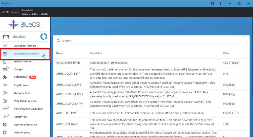
Parameters can be adjusted within BlueOS in the Autopilot Parameters menu or in QGroundControl.
In BlueOS
Click on Autopilot Parameters from the left sidebar. You can search for parameters using the top search bar.
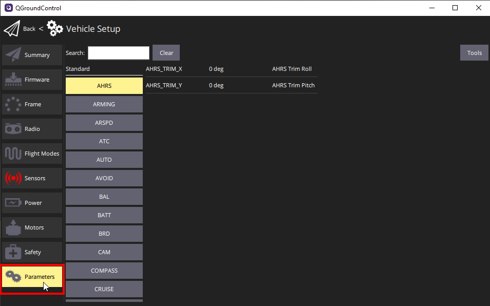
In QGroundControl
Click the Q icon in the top left corner of QGroundControl then select Vehicle Setup. Choose the Parameters menu from the left sidebar. You can search for parameters using the top search bar.
Failsafes
Failsafes are automatic safety mechanisms that are activated during specific problems or abnormal scenarios while operating the BlueBoat. They can protect the BlueBoat by responding to situations such as communication loss or low battery, and automatically taking the appropriate action.
Failsafes can be configured by setting the specified parameters directly.
The BlueBoat supports the following failsafe modes:
Ground Control Station (GCS) Failsafe (aka Telemetry Failsafe)
This failsafe is triggered if the vehicle loses communication (stops receiving heartbeat messages) with the ground station computer for a specified time period. This failsafe is enabled by default and has the following default behavior:
- The time period is controlled by the FS_TIMEOUT parameter, the default is 5 seconds.
- If communication is lost for at least 5 seconds, and the BlueBoat is not in Auto mode, the BlueBoat will switch to Hold mode. Hold mode will stop the motors and the BlueBoat will remain armed but will not attempt to hold position.
- If the BlueBoat is in Auto mode, and communication is lost, the failsafe is ignored. This behavior allows you to conduct autonomous missions without interruption even if the BlueBoat travels outside of communication range. Always be sure that your programmed mission brings the boat back into communication range.
This failsafe can be enabled and disabled with the FS_GCS_ENABLE parameter:
- Disable (value 0) will disable the GCS failsafe entirely.
- Enable (value 1) will execute the FS_ACTION when triggered.
- Enabled Continue with Mission in Auto Mode (value 2) will ignore the failsafe in an Auto mode mission but will execute the FS_ACTION if in any other mode.
The action taken when the failsafe is triggered is controlled by the FS_ACTION parameter:
- Nothing (value 0) will do nothing.
- RTL (value 1) will activate RTL (return to launch) to go home.
- Hold (value 2) will activate Hold mode. Hold mode will stop the motors and the BlueBoat will remain armed but will not attempt to hold position.
- SmartRTL or RTL (value 3) will activate SmartRTL mode to go back home or RTL if SmartRTL doesn’t work.
- SmartRTL or Hold (value 4) will activate SmartRTL mode to go back home or Hold mode if Smart RTL doesn’t work.
Battery Failsafe
This failsafe is triggered when the battery voltage drops below a specified value. This failsafe is not enabled by default and is not typically necessary if the voltage level is actively monitored. The battery failsafe can be helpful if you plan to operate a mission that will take significant time, and is located within one area (like a survey). This will ensure that if the power consumption is faster than anticipated, the batteries are protected by the vehicle aborting the mission early automatically. If you’re operating a long distance mission, traveling from one location to another, and will be outside of communication range, we recommend this failsafe remain disabled.
- The failsafe will trigger if the voltage drops below the voltage value held in the BATT_LOW_VOLT parameter for more than 10 seconds. If set to zero (the default value) the voltage-based trigger will be disabled.
- The BATT_LOW_TIMER parameter controls how long the voltage must be below the threshold for the failsafe to trigger (10 seconds default).
- If this failsafe is enabled, the BATT_FS_VOLTSRC parameter should be set to Sag Compensated Voltage (value 1).
- This failsafe also has a capacity-based trigger. We do not recommend using the capacity-based trigger.
The following will happen when this failsafe is triggered:
- A warning message will be displayed in QGroundControl (if within communication range).
- The BlueBoat will perform the failsafe action configured in the BATT_FS_LOW_ACT parameter.
The BATT_FS_LOW_ACT parameter controls the action taken when this failsafe is triggered:
- None (value 0) will do nothing (default).
- RTL (value 1) will activate RTL (return to launch) to go home.
- Hold (value 2) will activate Hold mode. Hold mode will stop the motors and the BlueBoat will remain armed but will not attempt to hold position.
- SmartRTL or RTL (value 3) will activate SmartRTL mode to go back home or RTL if SmartRTL doesn’t work.
- SmartRTL or Hold (value 4) will activate SmartRTL mode to go back home or Hold mode if Smart RTL doesn’t work.
- Terminate (value 5) will disarm the vehicle.
The battery failsafe can be configured as a two-stage failsafe. This allows setting up a follow-up action if the battery voltage falls below an even lower threshold.
- The BATT_CRT_VOLT parameter holds the secondary (lower) voltage threshold. Set to zero to disable. Default is zero.
- The BATT_FS_CRT_ACT parameter holds the secondary action to take. It has the same options and default as BATT_FS_LOW_ACT.
You can read more about ArduRover failsafes here.
Turning the BlueBoat On and Off
With batteries connected, power on the BlueBoat by turning the penetrator switch in the “ON” direction until it bottoms out.
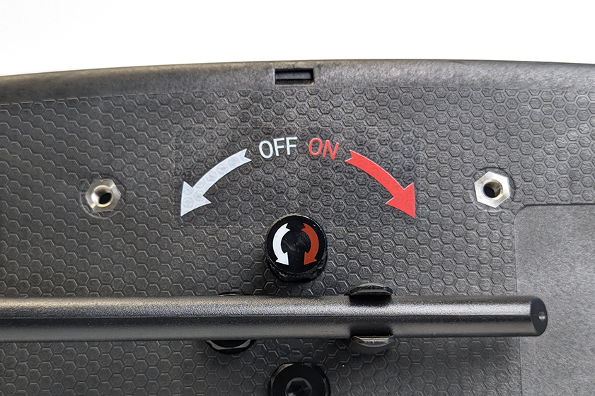
You should hear a beep and the Navlight will turn on after a few seconds indicating that the BlueBoat is powered on.
To turn off the BlueBoat, turn the penetrator switch in the “OFF” direction. The Navlight will stop flashing as an indicator that the BlueBoat is powered off.
Pre-mission Checklist
This checklist should be completed before heading out to the mission site to ensure operational readiness.
- Be aware of any regulations regarding the operation of USVs (uncrewed surface vehicles) for the mission site. Follow all local regulations and contact the appropriate local authority if required.
- Check the BlueBoat frame and frame bracket bolts are not loose.
- Check that the Crosstube is fully seated on the hose barbs and clamped securely by the hose clamps.
- Check that the hose barbs are fully secured to the hulls and cannot be rotated.
- Check propellers for damage.
- Turn the propellers by hand to ensure they spin freely.
- Check that the clamp levers are tight and the hulls cannot fold in inadvertently when locked.
- By hand, check that all bulkhead penetrations on the hatch lids are correctly installed and secure.
- Check all blank penetrators
- Check the NavLight
- Check the penetrator switch bulkhead
- Check any additional bulkheads you have installed
- Check that the bulkhead penetrators under the rear fairings are correctly installed and secure.
- Test your connection by opening QGroundControl and connecting to the BlueBoat. Always test using the computer you will use for the mission. See the Software Setup Guide if you have not already set up the connection.
- Download offline maps if necessary. The mission site may not have internet access or reliable mobile service to download maps for mission planning. In this case, the map data for the mission site can be downloaded beforehand. See the Downloading Offline Maps section for more information.
- Create and save your waypoint or survey mission, if desired. It may be convenient to create and save the mission plan in QGroundControl before reaching the mission site. More information about creating missions can be found in the Mission Planning section.
- Make sure the BaseStation is fully charged.
- Make sure all batteries are fully charged and their voltages are all within within 0.2 volts. The Battery Cell Checker can be used to quickly check the battery charge.
- Prepare the BlueBoat for transport if necessary:
- Fold antenna down and snap into holder.
- Fold BlueBoat and lock clamp levers.
- Ensure you have packed all necessary equipment. At a minimum, you need the following equipment to operate the BlueBoat:
- The BlueBoat
- The BaseStation
- Your ground control station computer
- Batteries
- Controller (recommended)
- Your payload (if applicable)
Setting up for a Mission
The following goes over the typical steps for setting up your equipment once you are at the mission site. These instructions assume you have already completed the software setup for the BlueBoat. See the Software Setup Guide If you have not done so already.
1. Assess the mission site to determine the best locations for launching the BlueBoat, positioning the BaseStation, and setting up the ground control station computer. Tips for positioning the BaseStation to optimize communication range can be found in the Positioning the BaseStation section.
2. Set up the BaseStation and turn it on.
3. Set up your ground control station computer and connect to the BaseStation via Wi-Fi or USB-C cable.
- Connect via Wi-Fi: The BaseStation creates a wireless network with the SSID “BaseStation – 2.4Ghz“. Open the Wi-Fi network menu and connect to it. The default password is “BaseStation“.
- Connect via USB-C cable: Use a USB-C cable to connect the BaseStation to a USB port on your computer.
4. Unpack the BlueBoat. Unlock the clamp levers, unfold the BlueBoat, then lock the clamp levers again.
5. Open the hatches.
6. Ensure all batteries are at the same charge level, within 0.2 volts, before connecting. Connect the batteries to the BlueBoat following the guidelines in the Connecting Batteries section.
7. Close the hatches and lock the latches.
8. Unfold the antenna.
9. Turn on the BlueBoat.
10. Start QGroundControl and wait for the BlueBoat to connect.
11. Arm the BlueBoat in Manual Mode and give it a quick throttle command to test the motors.
12. Check that the failsafes are configured correctly according to your preference and mission type.
You’re ready for launch!
BaseStation Antenna Range and Positioning
The communication range of an antenna is highly dependent on the operating conditions and environment. All the following are factors that will affect range performance while using the BaseStation:
- Local regulations. Most countries have regulations that limit the EIRP (Effective Isotropic Radiated Power) of an antenna. If a country has low EIRP limits, it restricts the amount of power that can be transmitted from an antenna, reducing the effective range of the antenna. In countries with higher EIRP limitations, antennas can transmit more power, leading to a longer range and better signal strength.
- Line of site. The BaseStation antenna requires a clear line of sight to the BlueBoat. Obstructions like buildings, trees, etc. will block the signal and significantly reduce range.
- High-bandwidth payloads. These use more of the radio link’s capacity and reduce range. Consider lowering network traffic to improve range.
- Weather. Heavy rain, fog, snow, or other inclement weather can cause signal attenuation and reduce range.
- Sea state. Rough sea conditions like heavy swells and waves can block or reflect the antenna signal. It can also cause the BlueBoat to pitch and roll more which may misalign its antenna and cause signal loss.
- Interference. Other nearby wireless networks, signals, devices, etc. can cause interference and reduce signal quality and range.
- BaseStation elevation. Raising the BaseStation is the best way to increase range. The lower the BaseStation is to the ground, the more likely the signal will be blocked by ground level obstructions or waves, or bounce off the water’s surface.
With all that in mind, the following are some guidelines for positioning the BaseStation to maximize range performance:
- The BaseStation requires a direct line of sight to the BlueBoat. Buildings, trees, or other obstructions will affect communication range performance.
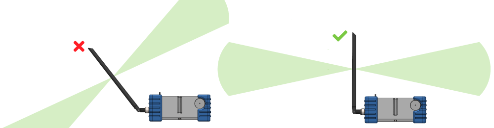
- Orient the BaseStation so the antenna side is facing in the direction of the boat.
- The BaseStation antenna must always be positioned vertically. Do not tilt the antenna towards the BlueBoat, this will reduce the range performance.
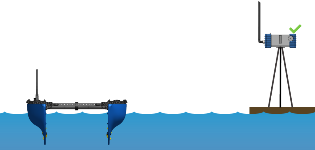
- Elevating the BaseStation is the best way to improve communication range. An easy way to do this is to mount the BaseStation on a tall tripod. The bottom of the BaseStation features both 1/4-inch and 3/8-inch standard tripod mounts to easily mount it to any tripod.
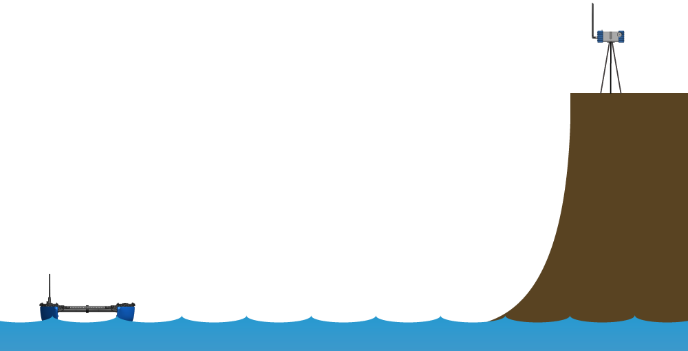
- Seek higher ground. In addition to using a tripod, setting up the BaseStation at a higher elevation, like a cliff overlooking the area of operation, will significantly increase range performance.
Operation
Safety and Best Practices
- Be aware of any regulations regarding the operation of USVs (uncrewed surface vessels) in your country. Follow all local regulations and contact the appropriate local authority if required.
- Always keep the BlueBoat within eyesight when in operation.
- Always keep the BlueBoat within radio contact range.
- Be prepared to take over manual control at any time.
- Be aware of your surroundings, especially the location of other vessels.
- Notify other vessels in the vicinity if possible and monitor appropriate radio channels.
- Avoid operating in busy waterways.
- Always use the visual warning flag.
- Do not use the BlueBoat to tow or carry people.
- Stay clear of the propellers whenever the BlueBoat is armed or in operation.
- Only handle or carry the BlueBoat while it is disarmed or powered off.
- Use all warning stickers provided in the BlueBoat kit.
- Avoid operating in the surf zone as heavy surf can flip the boat over.
Arming and Disarming
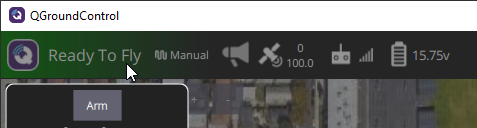
The BlueBoat will not respond to pilot input or perform any autonomous actions while it is disarmed. Only arm the vehicle when you are ready to begin operations and you have ensured it is safe to do so. The vehicle should be disarmed before it is carried or handled in any way, such as during launching and recovery. The vehicle can be armed and disarmed using controller button functions or through the QGroundControl user interface by clicking Ready To Fly on the top bar then clicking Arm.
Launching
Shore Launch- The boat can be pushed out or manually driven out from the shore.
- The propellers must be fully submerged to launch from the shore.
- The keel, which is the bottom of the hulls, is durable enough to drive over rough surfaces during a shore launch. Just be aware of and avoid any large rocks that may damage the propellers.
- The boat can be dropped into the water, such from over the side of another vessel or from a high dock.
- The maximum drop in height depends on the clamping force of the clamp handles. If the clamping force is too loose, the impact from a high drop can cause the hulls to fold in. The default clamping force allows for a maximum drop-in height of approximately two feet (.6 meters).
- The drop-in height can be increased by increasing clamp force or using the fixed-frame configuration.
- Also consider the durability of any attached payload when dropping the BlueBoat from height.
- Keep the angle of entry around 45°. Too steep of an angle may cause the boat to flip over.
Control Modes
The following are the most frequently used Control modes. Control modes can be enabled in the QGroundControl Fly View or by assigning the control mode to a button function on the controller. Detailed information about control modes and all parameters can be found in the ArduRover documentation.
- In Manual Mode, the controller’s steering and throttle sticks directly control the vehicle’s throttle and steering output.
- This mode does not require a position estimate (i.e. GPS is not required).
- It is recommended to always have one controller button function assigned to this mode.
- In Acro Mode, the steering stick controls the vehicle’s turn rate and the throttle stick controls the vehicle’s speed.
- The ACRO_TURN_RATE parameter controls the maximum turn rate the steering stick can request. The turn rate varies linearly from zero to ACRO_TURN_RATE as the stick input varies from neutral to full deflection. Once the input returns to neutral, the vehicle will attempt to hold heading, compensating for external influences, i.e. “heading hold”.
- The top speed is interpolated from the CRUISE_THROTTLE and CRUISE_SPEED parameters.
- Loiter Mode allows the boat to hold a position within a specified radius of a target position, good for holding in currents or while waiting for pilot input.
- While the boat is within the loiter radius (LOIT_RADIUS) of the target it simply drifts.
- If/when the boat strays more than the loiter radius from the target it:
- Rotates to point either directly toward the target or directly away from it (whichever results in less rotation).
- Drives/floats forwards or backward at 0.5 m/s x the distance to the edge of the circle around the target, but at a speed no greater than WP_SPEED.
- Change the LOIT_RADIUS parameter to adjust the distance from the target position the boat will drift. LOIT_RADIUS can be adjusted from 0 to 20 meters in increments of 1 meter.
- In Auto Mode, the vehicle will follow a pre-programmed mission stored in the autopilot which is made up of navigation commands (i.e. waypoints). More information about creating a mission can be found in the Mission Planning section.
- Plan and upload the mission to the BlueBoat as described in the Mission Planning section.
- Change the mode to Auto and the boat should begin executing the mission waypoint commands.
- You may regain manual control of the boat at any point during the mission by switching to Manual mode or any other mode.
- If a mission is interrupted (for example if you switch out of Auto mode before it has completed the mission) the last command executed is stored and when the boat is next returned to Auto mode it will resume the mission from this command. Disarming the vehicle or rebooting the autopilot will reset the mission back to the first command.
- In Guided Mode, you can command the vehicle to drive to a location specified by clicking on the map.
Waypoint Parameters
- Waypoint radius (WP_RADIUS): The distance in meters from a waypoint when it is considered the waypoint has been reached. This determines when the vehicle will turn toward the next waypoint. Can be adjusted from 0 to 100 meters in increments of 0.1 meters.
- Waypoint speed (WP_SPEED): Waypoint speed default. Can be adjusted in increments of 0.1 meters per second.
NavLight Flashing Patterns
While the BlueBoat is powered on, the NavLight will flash in various light patterns to indicate its status and current control mode.
| Light Pattern | Arm Status | Control Mode |
|---|---|---|
| Slow Single Pulse (20ms on, 2s off) [0.5hz] | Disarmed | - |
| Slow Single Pulse (20ms on, 2s off) [0.5hz] | Armed | Hold |
| Double Pulse (20ms on, 1s off) [1hz] | Armed | Manual |
| Double Pulse (20ms on, 1s off) [1hz] | Armed | Acro |
| Double Pulse (20ms on, 1s off) [1hz] | Armed | Steering |
| Double Pulse (20ms on, 1s off) [1hz] | Armed | Simple |
| Fast Triple Pulse (20ms on, 0.15s off, 1sec between flashes) | Armed | Auto |
| Armed | Guided | |
| Armed | RTL | |
| Armed | Smart RTL | |
| Solid On | Armed | Loiter |
Controller Button Layout
There is no preset default button layout, so you can configure the controller to your liking. Instructions for configuring the controller button functions are available in the Software Setup guide. If the controller is not behaving properly, review all the settings in the Controller Setup section of the Software Setup guide.
Monitoring Battery Voltage
4S LiIo/LiPo batteries have a full charge voltage of 16.8 V and are considered depleted when they reach 12 V. Do not allow the battery voltage to fall below 12 V or the batteries may be permanently damaged. The battery voltage is displayed in the upper left of the QGroundControl top bar.

Use the following battery endurance table to help determine how many batteries to use for your mission.
| Endurance @ 1 m/s (~30 W), no payload: | ||
|---|---|---|
| 2 Batteries (532 Wh, 2.4 kg) | 18 hrs (65 km) | |
| 4 Batteries (1064 Wh, 4.7 kg) | 36 hrs (130 km) | |
| 6 Batteries (1596 Wh, 7.0 kg) | 50 hrs (180 km) | |
| 8 Batteries (2128 Wh, 9.3 kg) | 62 hrs (220 km) | |
Occasionally check the remaining battery voltage. Consider how much mission is left and the distance from the launch point (home). Always leave enough charge for the boat to return home.
Recovering the BlueBoat
- Autonomous missions typically end with a Return to Launch (RTL) action or Loiter action.
- Manually control the boat to the recovery point if necessary. Drive the boat up the shore for a shore recovery. Avoid large rocks that could damage the propellers.
- Disarm the boat when you are ready to recover it.
- Recover the boat.
- Turn the boat off by turning the penetrator switch in the “OFF” direction.
- Fold in the antenna.
- Fold in the hulls and lock the clamp levers for transport, if necessary.
Post Mission Checklist
- Offload payload data, if applicable.
- Remove the batteries from hulls if the boat will not be operated again in the immediate future.
- Put the batteries at the proper voltage for storage (“storage charge”).
- Store the batteries in a safe location.
- Rinse off the boat with fresh water. This is especially important after operating in saltwater.
- Check the condition of the boat:
- Check that all bulkhead penetrations are installed and not loose.
- Check the frame and frame bracket bolts are not loose.
- Check propellers for damage.
- Check rear fairings for damage.
- Inspect the hulls.
Mission Planning
QGroundControl’s Plan View allows you to create missions made up of navigation commands (i.e. waypoints). These missions can be created ahead of time, even if the boat is not connected, then uploaded to the boat later. This section explains how to create a simple waypoint mission and a survey mission.
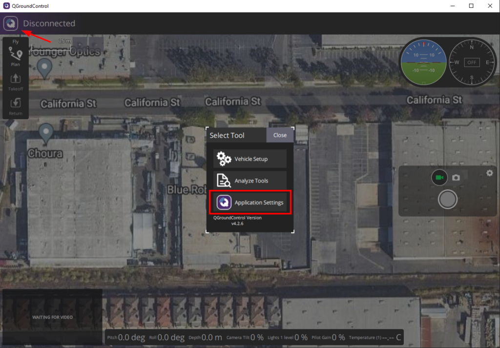
Before you begin creating missions, open QGroundControl’s application settings by clicking the Q icon in the top left corner then clicking Application Settings.
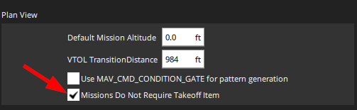
In General settings, in the Plan View section, enable the option for Missions Do Not Require Takeoff Item. You only have to enable this option once.
To create a mission, click on Plan from the QGroundControl Fly View.
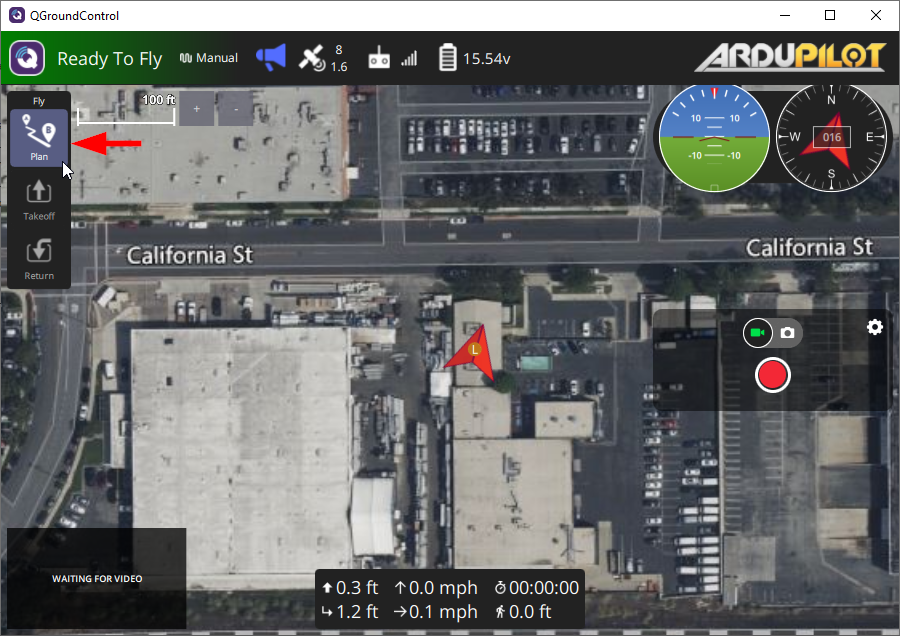
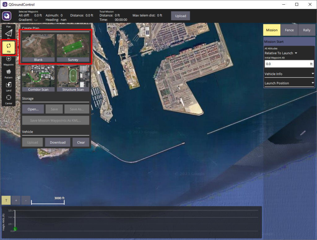
This will take you to QGroundControl’s Plan View where you can create and edit missions. You will be shown options to create different types of missions. If this menu does not display automatically, you can bring it up by clicking the File button on the left sidebar. Click on Blank to create a simple waypoint mission, or Survey to create a survey mission
Simple Waypoint Mission
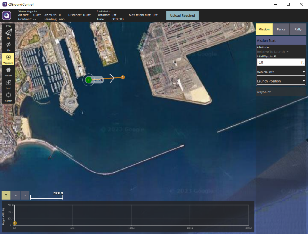
1. Click on Waypoint from the left menu. While the Waypoint tool is enabled, clicking on the map will add a waypoint in that location. The first waypoint you add will also add a Launch point. You can reposition this Launch point to the planned launch site for the mission (during the actual mission, the Return to Launch point [RTL] is set to the location where the boat was armed).
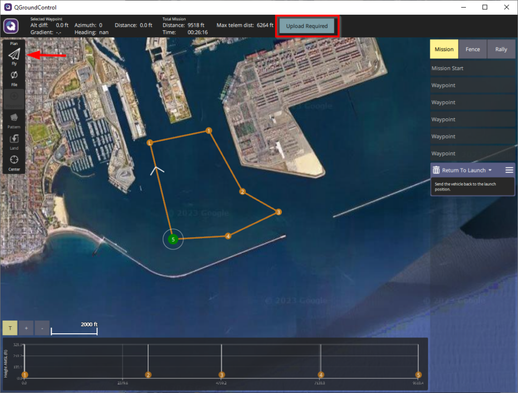
2. Waypoint items are added to the Mission Command List on the right as you add them to the map. The numbered order of the waypoints is the order that the vehicle will travel to each waypoint. To reposition a waypoint, click on it and drag it. To delete a waypoint, click on it then click on the trash can icon next to it in the Mission Command List. Add waypoints to plan the path you would like the boat to take.
3. After adding the last waypoint, you can add a Return to Launch (RTL) action by clicking on the Land button from the left menu. The boat will navigate in a straight path from the last waypoint to the launch point where the boat was armed. Keep this in mind and ensure the path the boat takes does not cause it to run ashore or run into structures.
4. When you are done planning the mission, click on the Upload Required button (if the vehicle is connected). Wait for the mission to be successfully uploaded to the vehicle. Click on Fly to return to the Fly View. If the boat is not connected, you can save the mission to upload later by clicking the File button from the left menu.
5. Set the BlueBoat to manual mode, put it in the water, and arm it. WARNING: sliding the onscreen “Slide to confirm” slider will automatically arm and start the mission! Do not slide this slider unless you are ready to start the mission.
6. When you are ready to start the mission, switch to auto mode and the boat will begin the mission.
7. The boat will return to launch then automatically switch to loiter mode at the end of the mission.
Survey Mission
The survey mission feature of QGC is a powerful method of laying out a grid-style survey route. You’ll outline the survey area on the map, choose a survey line spacing, and adjust the angle of the route. Once you’re satisfied, it’s easy to upload the mission as you did with other waypoint missions. It might take a bit longer, especially over slow communication links, to transfer these missions because they contain significantly more waypoints.
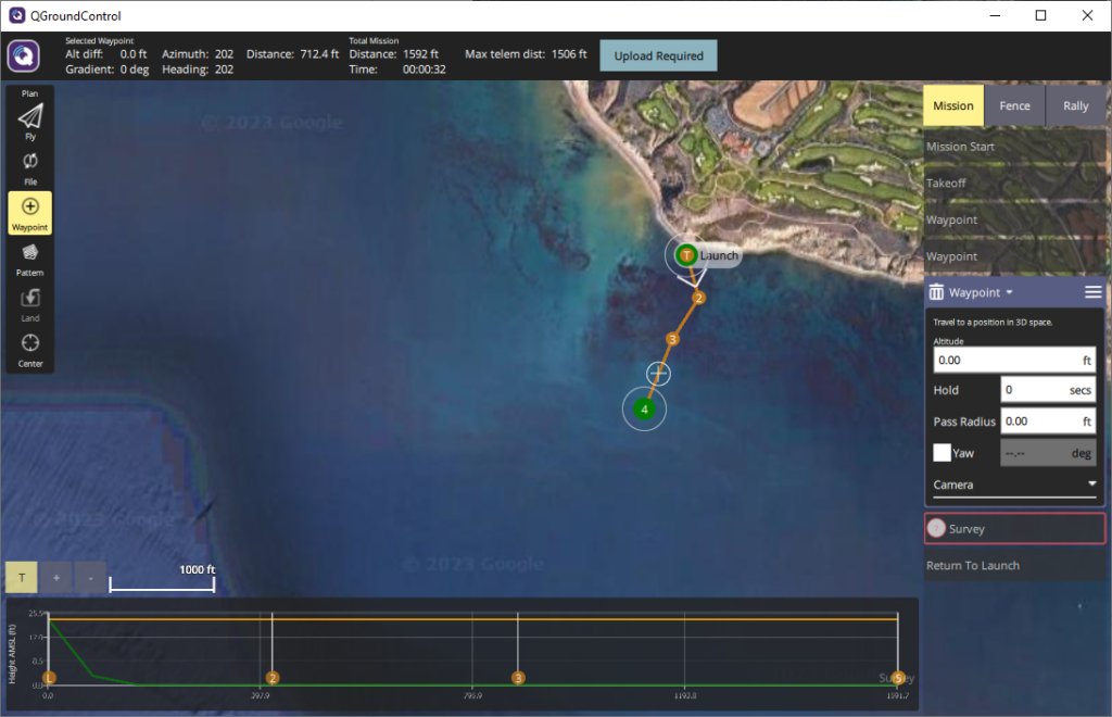
1. When you create a survey mission, Takeoff (Launch), Survey, and Return To Launch mission items are automatically added to the Mission Command List on the right side. Move the Takeoff waypoint to the planned launch location on the map. Add normal waypoints using the Waypoint tool as detailed in the previous section to navigate the boat around any obstacles between it and the survey area. If no waypoints are added, the boat will follow a straight path from the Takeoff point to the survey area.
2. Next, select the Survey mission item from the Mission Command List, a Polygon Tools menu will appear at the top-center of the map. This is the tool you will use to define the survey area. There are options for Basic, Circular, and Trace.
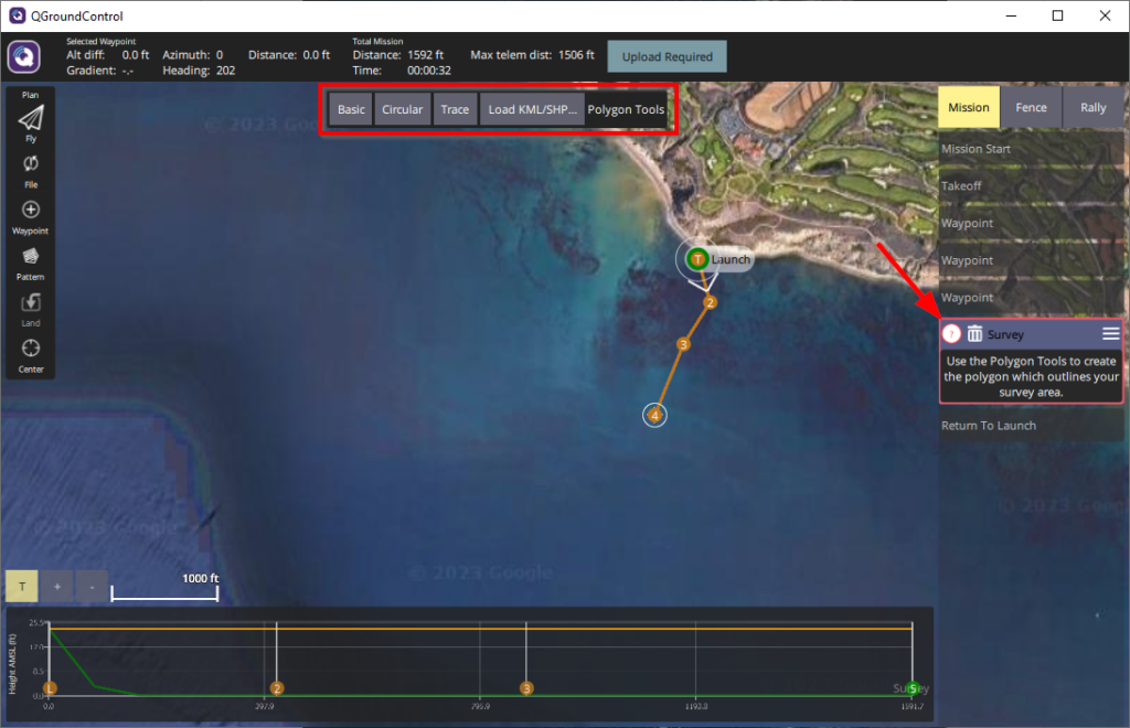
- Basic creates a square area. The vertices can be repositioned and more vertices can be added by clicking the “+” symbol between vertices to further define the survey area. The entire area can be repositioned by clicking and dragging on the center of the survey area.
- Circular creates a circular area. The circle can be resized by clicking and dragging the circle icon at the edge of the circle. The entire area can be repositioned by clicking and dragging on the center of the survey area.
- Trace allows you to manually add points to outline the survey area. The vertices can be repositioned and more vertices can be added by clicking the “+” symbol between vertices to further define the survey area. The entire area can be repositioned by clicking and dragging on the center of the survey area. Click Done Tracing when you are satisfied with the green area outlined.
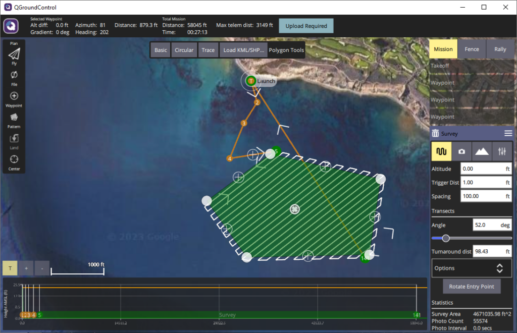
3. With the survey area defined, you can now adjust the transect settings.
- Spacing is the distance between transects. When planning line spacing, it is important to consider your application. Surveying with a camera may require low spacing, while a sonar would require greater spacing—but both are dependent on depth! This is because of their respective field of views or beam widths, as well as the desired amount of overlap between each transect.
- Angle is the angle of the transect lines, relative to North.
- Turnaround dist. controls how far the boat will navigate outside the survey area to turn around and line up its approach. For many cases, this value can be small, less than 2 meters (6 feet). However, if you are using the boat with a towfish, you may need to increase this to allow enough distance for it to be aligned behind the vehicle before starting a transect.
- Rotate Entry Point swaps the start and end point of the survey.
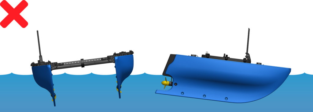
4. Finally, it’s important to add waypoints or move your launch point so that after the survey, a Return to Launch action does not cause the boat to attempt to become amphibious. In the example below, you may notice the orange line from the final 56th waypoint of the survey leading back to the launch point takes the boat over ground, not good.
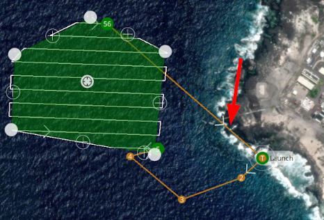
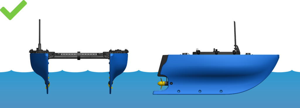
To correct this, either delete the Return To Launch mission item, or add additional waypoints after the survey to guide the boat through a safer route. If you chose for the vehicle to not return to the launch point, ensure you will be within radio range of the final waypoint! Having the vehicle return only to a nearby waypoint is generally easier, so that it can be navigated to shore or a vessel for recovery at your discretion.
5. When finished, click the Upload Required button at the top of the page. A green bar will appear, loading from left to right. If the data connection is poor, some mission items may be missing, even if the mission upload succeeded. Click Fly to switch to the Fly View to see the mission on the map, and if elements are missing, try to upload again.
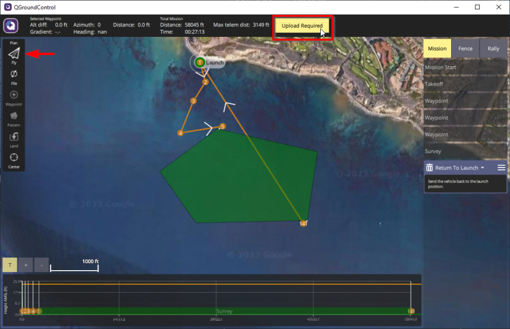
6. You’re now ready to go! With the boat in the water, the mission can be started by switching to Auto Mode, or by using the slider on the bottom-center of Fly View. Make sure the vehicle’s path is clear, and monitor it during the survey to avoid any surprises!
QGroundControl has many powerful tools to help create complex missions. We recommend watching this video tutorial as well as checking out the QGroundControl resources to learn more.
Downloading Offline Maps
The mission site may not have internet access or reliable mobile service to download maps for mission planning. In this situation, the map data for a location can be downloaded in advance. To download an offline map in QGroundControl:
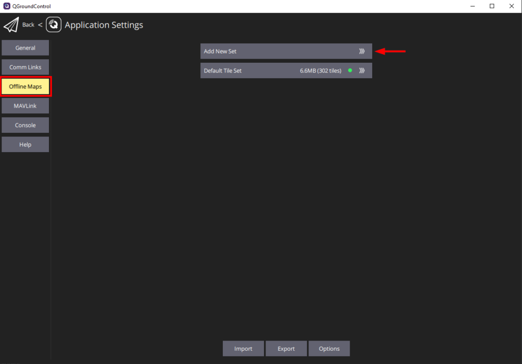
1. In the QGroundControl, position the Map View in the general area of the map you would like to download. Click on the “Q” icon in the top left corner and select Application Settings.
2. Select Offline Maps from the sidebar and click on Add New Set.
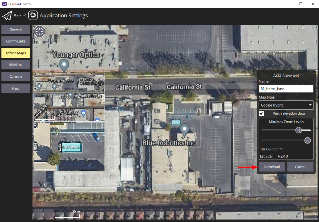
3. The next screen allows you to edit the options for the new offline map. You can edit the name for the new map, change the map type, and set the minimum and maximum zoom levels for the map. You can drag the map to reposition it, a preview of the minimum and maximum zoom levels are also displayed. Click Download when you are done to download the offline map.
Next Steps
Head over to the BlueBoat General Integration Guide to learn about the various ways BlueBoat supports integrating payloads.