
Building DART: A BlueOS-Based Vertical Profiling AUV
By Tony White
One of the first questions most people ask when coming across a BlueROV2 (and sometimes even a BlueBoat) is “How deep can it go?!” In practice, tether length and water currents usually set your real depth limit — not the component ratings. But what if you got rid of the tether?!
A common goal in aquaculture, especially when conducting site surveys for future farms, is to determine what exactly is on the bottom. Beyond satisfying the age-old curiosity to know what’s down there, identifying your seafloor type is key to choosing the right anchor type and designing an effective mooring.
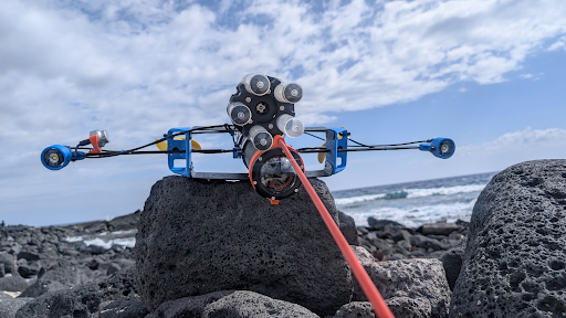
This guide is a write-up of a quick development effort that created a vertical profiling AUV code-named DART (Descend, Assess, Return, Transmit). Unlike a dropcam, which sinks to the bottom to stay put for a long time, typically releasing a weight to return to the surface (leaving it behind), DART takes an active approach. The DART does not have a tether connection to the surface, so there is no way to directly retrieve it or view video in real time at the surface, like with an ROV or tethered camera. It is always positively buoyant (hopefully), and motors itself straight down. Using minimal code, the DART reaches depth, runs lights, and records video following a scripted mission profile, successfully tested to 400 meters.
By the end of this guide, you’ll come away with:
- An understanding of how the vehicle is controlled via external switch and Lua script within the ArduSub/BlueOS framework
- Familiarity with the SubReels: AUV video-recording extension, and inspiration to develop your own
- Field test results — video and logs — so you can evaluate the kind of data a system like this collects
Whether you replicate the design exactly or adapt the methods to your own application, let’s get started by determining…
Development Goals
My friend and former coworker, Gavin Key, COO of Ocean Era, came to me with a need for this unique vehicle. I wanted a simple project to show how an ArduSub vehicle running the Navigator/Pi stack can be made autonomous, and just how easy BlueOS extensions make adding on functionality. Gavin needed to observe some bottom conditions at the extreme depth of 400 meters, comparing sites for the installation of an exciting blue-field algae growing array test project. We agreed on the following dive profile, and I set out to develop some hardware to make it happen.
- Put DART in the water, and trigger a countdown to descent (this is like model rocketry in reverse!)
- The vehicle descends at a desired rate, until:
- It reaches the programmed maximum depth, or
- It strikes the bottom (depth stops changing)
- Once at this max depth, the vehicle ascends to a programmed distance above the “strike” depth or a maximum depth set-point (set based on component depth rating or max desired depth to attempt).
- When at this hover depth, the vehicle maintains its vertical position until the hover time has elapsed, freely drifting with the currents.
- The vehicle then floats to the surface — this is intended to happen passively, but as the syntactic foam on hand wasn’t quite rated for the depth it would be subjected to, the code would run the motors if necessary to maintain the desired ascent rate until it returns.
- Once at the surface, the vehicle remains in depth-hold mode until the switch is opened and closed again, restarting the cycle.
- At user-set depths, the system will turn on the lights, and start / stop video recording. To experiment with exposure in this complete darkness, the brightness of the lights would ramp from 0 to 100% during the hover period — at least for the first test to this depth! Spoiler alert — when down in the deep inky blackness, the more light the better! That was proven to be the case in the clear waters of Hawaii at least, but backscatter in other environments could impact this. Other actions, associated with payloads, may also need to occur at different depths or points of the mission.
If all went well, we would have video from the deep that would tell us what the bottom type was — rock, coral, or ideally sand, confirming conditions previously observed and matched to the anchor type — large clumps of chain in this case!
Designing the Vehicle
Version 1
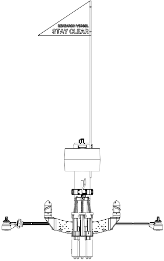
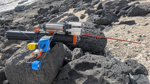
The DART can be thought of as what would come out of a productive collision between the BlueROV2 and the BlueBoat. It was conceived to be passively stable, although it would turn out that active roll control needs to be correctly configured, even if the vehicle passively wants to stay vertical on its own! It uses M200s with weedless props for high efficiency at (vertical) speeds of up to 2–3 m/s, and is lazily optimized to be fairly low drag (due to a small cross section) in that vertical direction, A Pi4/Navigator stack with the ROV power sense module let the system monitor the battery and have the standard Blue Robotics “brain.”
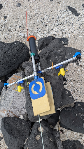
A couple of Basic ESCs, the new RGB indicator, a Bar100XT, the Lumen Light pair, and an on/off Switch round out the first version’s accessories. The “hull” is made of two 3” cylindrical enclosures, 300 mm long, with the upper one completely empty serving as buoyancy to keep the vehicle correctly oriented even if the foam crushes completely.
The lower cylinder holds a standard Blue Robotics 4S 18Ah Battery, and all the electronics, including a low-light USB camera on a fixed mount. This first prototype uses an extended flange to provide sufficient volume for battery and electronics, leftover from an abandoned development effort (and not available for purchase, see version 2!). The max depth rating is driven by the dome — 500m.
The Blue Robotics High Visibility Flag was used to see the unit at the surface from great distance. A fiberglass stake from the hardware store acts as a “poker” to probe the bottom with an element less sensitive to impact than the camera dome!
Version 2
The second version of the DART used identical autopilot hardware, including the power sense module and UBEC 5V supply, but moved the electronics from the bottom “nose” of the vehicle to the top of the now ~700 mm long enclosure. This is enabled by the 3″ Coupler Flange, a new product that joins standard enclosure tubes end-to-end, creating a single longer pressure housing from multiple shorter tubes. In this vehicle, it mates two 3″ 300 mm Aluminum Tubes into a single ~600 mm enclosure, giving enough room to separate the battery and camera in the nose from the electronics and camera at the tail. That physical separation matters: it moves the center of gravity lower for passive stability, and keeps wiring runs simpler. Without the Coupler Flange, achieving this layout would have required a very long tube, which is very tough to make!
A set of 150 mm RAILS were used in conjunction with two 3D-printed parts to hold both the Raspberry Pi/Navigator stack, and a (trimmed) power bus-bar as well. This provides ample room to wire the remaining components, leaving the UBEC, Basic ESCs, and a large supercapacitor “floating” in the housing. The capacitor was used so that when powering from a supply on the bench, the inrush current during motor testing doesn’t cause the vehicle to reset due to the brief voltage drop! With the electronics mounted at the tail the thruster wires can be standard lengths (in the initial version, they had to be extended to go around the battery). The motors connect to the two ESCs, with the Lumen Lights, pressure sensor I2C cable, and on/off Switch also connected across the short distance from top End Cap to components.
Version 2 used an IP camera with a single cable running from nose to tail. When using this IP camera, connecting to a surface tether required either disconnecting the camera or installing an ethernet switch. A USB camera with an extension cable would have worked just as well, but the IP camera offered higher quality 4K video.
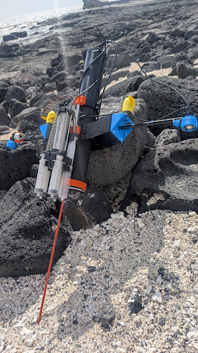
Finally, the battery goes in the bottom tube of the vehicle, offset from the dome only by the camera itself. A pair of ROV roof racks combine to form the “wings” of the vehicle, with ample mounting parts for payloads. Brackets on either side hold both the propulsion motors, and help secure a 400 mm set of RAILS. These were used to put the Lumen light pair far apart and parallel to reduce backscatter affecting the camera. A 5 chamber, 60 ml syringe Pascal water sampler made by PragmaTech was secured with a couple of 3D printed blocks, and its stainless mounting tube helps serve as a guide when mating the tubes to the coupler flange.
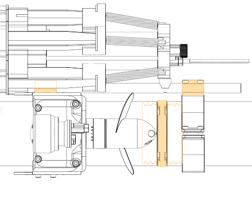
This tube also serves to reinforce the joint against cantilever loads, which are otherwise taken by the locking cord. To collect video footage verifying the desired operation of the water sampler, an external exploreHD Camera was used to record a secondary camera angle. That angle on the vehicle may not be necessary depending on your application, but gives great “selfies” of the action. The breakdown of the 7-port end cap used on the vehicle is shown in the table below, followed by the bill of materials.
| Enclosure Port Number | Component |
|---|---|
| 1 | Port side M200 |
| 2 | Starboard side M200 |
| 3 | Lumen Light pair |
| 4 | Bar100 XT |
| 5 | exploreHD Camera |
| 6 | Mission triggering On/Off Switch |
| 7 | Payload: PragmaTech Water Sampler |
The Subsea Foam was cut into two rings with a jigsaw, these were held together with long stainless-steel wood screws, and painted white. Some retroreflective tape was attached around this to maximize visibility! They attach to the vehicle with a 3D printed collar and a couple shorter wood-screws.
Bill of Materials
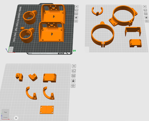
The following tables show a breakdown of all the parts used for the build, the first showing the Blue Robotics hardware components and the second all of the 3D printed components. You can download a compressed folder with all the step files from here (recommended print with 4 perimeters and 20% gyroid infill). And the complete design files are available on Onshape here.
| Blue Robotics Item | Cost | Quantity | Total |
|---|---|---|---|
| BlueROV2 Roof Rack | $57 | 2 | $114 |
| M200 Motor | $185 | 2 | $370 |
| Lumen Subsea Light (Pair) | $385 | 1 | $385 |
| Low-light HD USB Camera | $120 | 1 | $120 |
| DWE exploreHD USB Camera | $325 | 1 | $325 |
| Navigator Flight Controller | $220 | 1 | $220 |
| Raspberry Pi 4 | $65 | 1 | $65 |
| Lithium-ion Battery (14.8V, 18Ah) | $425 | 1 | $425 |
| 3" 300 mm Aluminum Watertight Enclosure Tube | $294 | 2 | $588 |
| 3" Coupler Flange | $50 | 1 | $50 |
| 3" O-ring Flange | $40 | 2 | $80 |
| 3" Watertight Enclosure Dome | $34 | 1 | $34 |
| 3" Watertight Enclosure Aluminum End Cap 7 x M10 Hole | $18 | 1 | $18 |
| Basic ESC | $40 | 2 | $80 |
| 5V 6A Power Supply | $32 | 1 | $32 |
| Power Sense Module | $92 | 1 | $92 |
| Watertight Enclosure RAILS (Narrow - 400N) | $39 | 1 | $39 |
| Watertight Enclosure RAILS (Narrow - 150N) | $29 | 1 | $29 |
| Switch | $28 | 1 | $26 |
| Subsea RGB LED Indicator | $23 | 1 | $23 |
| Bar100 XT | $380 | 1 | $380 |
| Subsea Buoyancy Foam: R-3318 (24 in x 8 in x 2.5 in) | $216 | 1 | $216 |
| $3,711 |
| 3D Printed Parts (PETG recommended) ~360 grams total | Quantity |
|---|---|
| Motor Mount | 2 |
| Lumen Mount | 2 |
| Rail Mount (External) | 2 |
| Raspberry Pi Mount | 1 |
| Bus-bar Mount | 1 |
| Camera Mount | 1 |
First Time Setup
The initial software setup was similar to a standard ROV — connect to the vehicle through BlueOS, calibrate the sensors, and make sure everything moves as expected. The DART was set up to use the standard BlueROV2 frame type, since that gives you two vertical thrusters on either side of the vehicle’s center, which is exactly what we needed for depth control.
The biggest hard-learned lesson was that thruster direction setup can be tricky. Merely checking that both are going the correct direction at the same time is not enough – they need to react correctly to stabilize vehicle roll! Checking the behavior while armed and in stabilize mode is a must after you assemble it for the first time. Adjusting the directions once tested is easy — you can either reassign them in software through BlueOS, or just swap any two motor wires while the enclosure is still open. Worth keeping in mind if you’re building something non-standard!
Before use, the vehicle motion sensors need to be calibrated. Since this is a unique vehicle layout, “nose down” is actually laying the vehicle on one side, and nose up the opposite side – given that the normal orientation is camera-down, a head-on view of the vehicle is a “+” shape. The vehicle can be balanced on each of the lights for left-side/right-side orientation. Upside down is pointing the camera at the ceiling/sky.
With the vehicle now calibrated, let’s open Cockpit! No need to worry about video streams for the moment — we’re going to check that the motor outputs are connected correctly. Hold the vehicle so that it is pointing camera down with the lights level with each other. Change the vehicle to stabilize mode via the mode selector, and then arm the vehicle. You’ll now roll the vehicle side to side, so that the lights are closer or farther from the ground. You’re watching to confirm that the direction the propellers spin would stabilize the vehicle. In other words, if you lower one side, the propeller on that side should blow air downwards toward the floor to try to lift the vehicle back to level orientation. The same should be true for the opposite side! If this isn’t the case, you’ll want to physically swap the ESC connections on channels 5 and 6, or make the swap of the motor functions on channels 5 and 6 on the PWM output page in BlueOS Vehicle Setup. Note: skipping this step, on two separate occasions, was a mistake made during development! Oops 😅
The vehicle is now set up and ready to start diving — it just needs some software to record video and control it!
Developing SubReels: AUV
Normally, the BlueROV2 sends its video feed to a user’s laptop on the surface via the tether, where the recording is typically saved. However, for untethered operation deep underwater, video must be saved onboard. To avoid creating lengthy recordings of non-essential footage, the video needs to be recorded only when required.
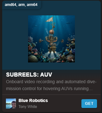
SubReels: AUV is a video recorder extension that allows AUVs to begin recording onboard when prompted by another service via HTTP request.
This extension was largely created through a great workflow for ‘vibe coders’: using LLM AI (Claude Opus latest flagship models) within the Cursor IDE. This approach is ideal for those who have some foundational knowledge but lack extensive software development experience, enabling them to quickly get the extension ready. A paid account was used, but the “tokens” consumed to create applications like this typically cost around $5.
The extension is generally built upon an example extension repository, featuring a Python backend and a Vue 2 front-end. After testing the extension via manual installs, I renamed it and submitted a pull request to the Extensions Manager library – now it is a one-click install for any BlueOS user!
The developed extension includes an HTTP endpoint to control the starting and stopping of recordings. Initially, this was hardcoded to capture the video from /dev/video2. Important: This means that the USB video device should not be configured on the BlueOS Video Streams page, as the extension requires exclusive access to it. Consequently, you will not see a video stream in Cockpit when connected. The extension was later updated to also record an RTSP stream from RadCam; note that other IP cameras might require a different hardcoded RTSP stream endpoint.
In a bit of feature creep, the extension was set up to fetch useful metrics from the autopilot and record them to a subtitle file, to make a better “deliverable” after the dive. The http endpoint is used by the Lua script, which you can find on the extension’s GitHub. All together, this lets the autopilot control video recording!
If you’d prefer to try other solutions, try using the recently released DashCam Extension, or the automatic video recording functionality being developed in BlueOS 1.5 beta. Log files in the .mcap format are created automatically, with video playing back in conjunction with telemetry using the powerful data visualization tool Foxglove. As this feature is still under development (beta) , users should test it thoroughly and not expect stability until it is officially released on the stable channel.
Developing the AUV Control Script
LUA is a language that our AI friends describe as “… a lightweight, powerful, and versatile scripting language designed for embedding in applications, known for its simplicity, efficiency, and ease of integration with other languages, particularly C and C++.” In the context of ArduPilot, it is an incredible way to add complex functionality to the autopilot system without having to modify the source code of the autopilot. This means you get to avoid the hassle of compiling and deploying autopilot firmware, which can be a tricky process to get set up, and is always a bit time-consuming. You can quickly iterate and test your LUA script in a simulation environment so that when you go to the field, you can be (much more) confident things will work as desired! Check out our docs on Lua scripts here.
A Quick Aside: Using AI for Lua Development (and Other Configuration)
LLM-based AI tools have become genuinely useful for ArduPilot Lua scripting — but only if you give them good context to work from. Given a vague prompt, many models will hallucinate API calls that don’t exist. The trick, beyond just using “plan” mode, is to feed them up-to-date references: working examples from your own codebase or other developers’ repositories, the ArduPilot Lua script examples, and relevant extension development resources and of course BlueOS itself! For this project, these were particularly helpful starting points:
- BlueOS Extensions development documentation
- ArduPilot’s Lua scripting bindings documentation
- BlueOS
- Tony’s GitHub – extensions and Lua scripts from a serial vibe-coder
- Rafa’s example Cockpit websocket connection extension
With those (and more) as context, the workflow becomes iterative: describe what you want the script to do, test the output in SITL, and feed back any error messages or unexpected behavior. For a vehicle that you can’t easily debug in the field, this loop of writing, simulating, and refining was essential. The newer agentic models can even run tests and iterate toward a solution on their own, which could someday make the development cycle even faster.
Before diving into code, it’s worth planning the architecture in a “plan” mode first — outline the features, requirements, and specific relevant examples and documentation. This was especially valuable for designing the state machine, where getting the transitions and edge cases right up front saved a lot of debugging later. It was also helpful to specify how each state should use the existing autopilot features – maintaining throttle to hold depth is done much more efficiently from within ArduSub than an external script.
This same approach works well beyond Lua. Foxglove layout files, for example, are JSON-based configurations that are tedious to write by hand but easy for an AI to generate and tweak when given a working example and a description of what telemetry streams you want displayed from MCAP files.
How This Lua Script Controls the Vehicle
The dive is managed by a Lua script running on the ArduPilot autopilot, built around a state machine that walks through each phase of the mission: STANDBY, COUNTDOWN, DESCENDING, ASCEND_TOHOVER, HOVERING, SURFACING, and COMPLETE (with an ABORT state just in case).
All the key dive parameters — target depth, descent throttle, hover duration, light activation depth, recording depth — are registered as ArduPilot parameters under a HOVER_ prefix. That means you can tweak the entire dive profile between missions through the BlueOS AutoPilot Parameter editor without touching any code! Going from a 60m test dive to a 410m deep dive is just a matter of changing HOVER_T_DEPTH. For more info, see the GitHub repository.
The mission kicks off when a physical switch on the vehicle is closed, starting a countdown before the script arms and begins the descent. During the dive, the script drives the vertical thrusters directly in manual mode, slowing the descent as it approaches the target depth. It also watches for bottom strike — if the descent rate suddenly drops, it knows the vehicle has hit the seafloor and transitions to ascending toward the hover depth. Once there, it hands off to ArduSub’s built-in altitude-hold controller to maintain position for the configured hover period by entering alt_hold mode. If an altitude source from a Ping sonar, DVL, or other rangefinder source was available, SurfTrack mode could be used to follow the terrain during the drift.
Video recording and lights are triggered automatically by depth thresholds. The LUA script talks to the Sub Reel extension over a simple TCP socket and controls the lights via RC channel overrides. One lesson learned: we initially had a fancy light ramping scheme (gradually turning up brightness during the hover), but in the complete darkness at 400m with clear water, just running the lights at max brightness would turn out to be the best approach.
The full annotated script is available on GitHub for anyone who wants to dig into the implementation details.
Testing in SITL (Software in the Loop)
ArduPilot includes a software simulation environment called SITL (Software in the Loop) that lets you test everything from the comfort of your desk (or couch). For a vehicle that’s going to be untethered and sinking to 400m with no way to intervene, this turned out to be arguably the most important part of the development workflow.
The setup is straightforward — in BlueOS, you switch the AutoPilot board to SITL, and it replaces the real-world sensors with a simulated environment. Your virtual vehicle now thinks it’s in a lake in Brazil (can you guess why?) that’s 50m deep. For this vehicle, it was especially helpful to play with the SIM_BUOYANCY parameter to test the ascent logic — you can make the simulated vehicle more or less positively buoyant and verify that the script correctly applies upward thrust when passive buoyancy alone isn’t enough to make it to the surface.
Rather than needing to physically flip the switch to start a mission, the script includes a HOVER_SIM_MODE parameter that simulates the switch cycle automatically. Set it to 1, and after a short delay the virtual vehicle arms, descends, hits the virtual bottom at 50m, hovers, and surfaces — exercising the full state machine without any interaction. It even auto-resets and runs consecutive missions, which is great for catching edge cases.
The simulated dive exercises everything: the countdown, descent with dynamic throttle adjustment, bottom-strike detection, altitude hold during the hover, and surfacing. Light commands and video recording triggers fire at their configured depths too — you can verify the timing by watching the message log in Cockpit. And the log from each virtual dive can be reviewed in a tool like the ArduPilot Log Viewer or Foxglove (BlueOS 1.5+) to check depth profiles, state transitions, and throttle behavior against expectations.
Switching back to real hardware is just a matter of changing the board back to Navigator in BlueOS — your real-world parameters and calibration are restored.
Closing the Loop — Iterating Your Lua
When errors occur in the Lua script, ArduPilot reports them as messages in the GCS — you’ll see them in Cockpit’s notification area with details like the line number and error type (for example, a nil value access or a failed parameter binding). By feeding these error messages back to the AI along with the context of what you were trying to achieve, it can suggest targeted fixes. The cycle of editing the script in the BlueOS file browser, restarting the autopilot to reload it, observing the behavior in SITL, and refining based on the results is where the development really happens. Because each iteration takes only seconds to restart rather than requiring a trip to the water, you can work through dozens of refinements in a single sitting — tuning throttle step sizes, adjusting grace periods for impact detection after water sampling transitions, or adding entirely new states like the WATER_SAMPLING phases in V2. Once the simulated dive profile matches your expectations, you can switch back to the Navigator board and head to the field with much higher confidence that the mission will execute as designed.
Field Testing!
Like many projects, this one stretched out considerably longer than expected — this guide was actually blocked waiting on the launch of the coupler flange, because we wanted to make sure you could start building your own version right away. The video below captures moments from across the development journey, including early prototype testing, the first dive to 400m, and testing of the second version of the vehicle described in this guide.
You can download the log from the dive here to review the telemetry and parameters, and the raw video from the dive is also available.
If there’s one takeaway from field testing, it’s that simulation can’t catch a wiring mistake. On two separate occasions — once per vehicle version — the motor output channels for left and right were swapped, and the vehicle immediately lost its mind trying to hover. The code was fine! The wires were not. It’s a humbling reminder to physically verify your motor directions and placement with the vehicle in hand before deployment, not just trust that the simulation gave you a green light.
The V2 water sampler logic told a similar story. It worked perfectly in SITL’s calm simulated lake, but the real ocean had other ideas — the vehicle was slower to pick up descent speed after a sampling pause, and the oscillating water column made the depth readings noisier. The result was false bottom-strike detections early in the dive, which made adding a grace period after each sampling hover necessary to let the vehicle accelerate before the script started watching for impacts again.
None of this went as smoothly as planned, but that’s kind of the point. Each test is a great one if it breaks something, each fix makes the system a little smarter, and along the way, a vehicle can make it to 400m and come back on time with great footage. If you’re building a DART AUV like this, expect a few “why is it doing that?!” moments on the way to success — they’re part of the process, and they make the end result that much sweeter.
Authors

Tony White
Tony White earned his Mechanical Engineering degree from Georgia Tech in 2012 and began his career with large autonomous hydrographic survey vessels with C&C Technologies (Louisiana) and ASV Ltd. (England). He later moved to Los Angeles to join Ocean Lab, where he helped design and deploy a swarm of 50 marine surface drones—the “Data Diver”—his first major project using Blue Robotics components. After some aquaculture experience in Los Angeles, he went on to Forever Oceans in Hawaii (and Panama), where he developed innovative camera monitoring systems and resident BlueROV2 platforms for remote fish mortality extraction. Since 2023, Tony works in Blue Robotics’ Product Experience and R&D departments, where he assists customers with applications and tests both in-house and third-party products, the latter evaluated for potential resale on the Blue Robotics “Reef.”