
Watertight Box User Guide
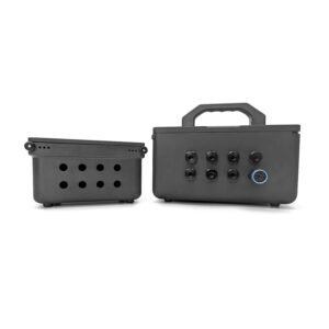
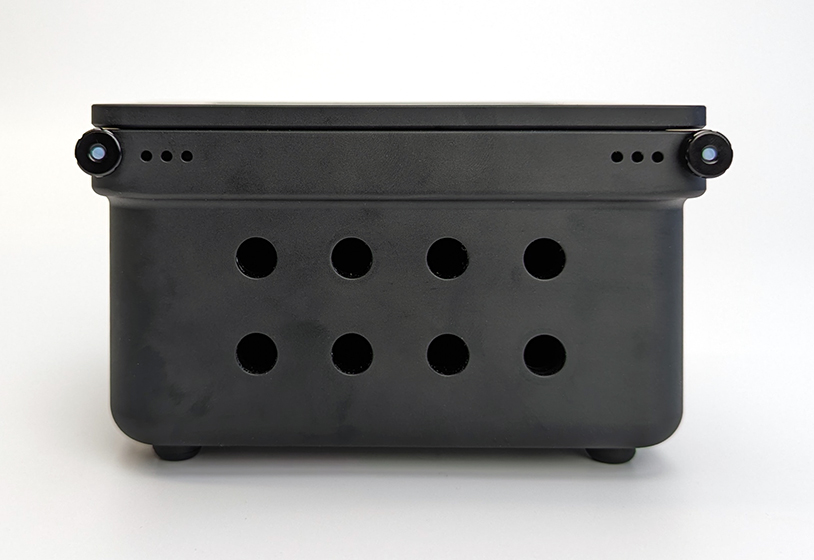
The Watertight Boxes are pressure-rated, corrosion-resistant, and flexible enough to use in many different applications. This guide will show you how to assemble and use your Watertight Box.
General Information and Safety
Using a Pressure Relief Valve
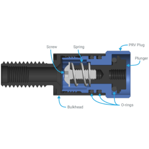
Every Watertight Box must have a Pressure Relief Valve (PRV) installed. The PRV acts as a vent to release pressure while opening or closing the box. It is also essential for safe operation. The Watertight Box lids have a large surface area, and any build up of internal pressure can quickly create a hazardous situation. The Pressure Relief Valve is designed to automatically release any internal pressure in a safe manner.
Pressure Relief Valve Installation and Usage
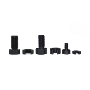
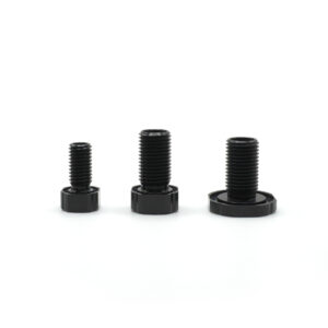
Bulkhead Sizes
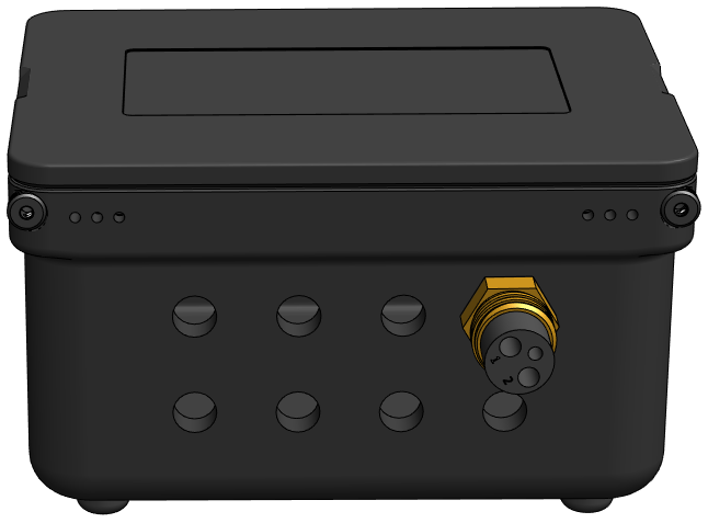
Many Blue Robotics products use the M10 bulkhead form factor for bulkhead penetrations. The Pressure Relief Valve, Switch, pressure and temperature sensors, and WetLink Penetrators for cable pass throughs all use M10 bulkhead penetrators. The Watertight Boxes feature only M10-size holes for M10 bulkheads. The M10 holes can be drilled out larger for M14 bulkheads, or additional holes can be drilled through the box.
M10 bulkheads can be installed using the M10 size Bulkhead Wrench or a 16 mm wrench.
M14 bulkheads can be installed using the M14 size Bulkhead Wrench or a 20 mm wrench.
Long-term Submersion
Galvanic corrosion occurs when two different types of metal come into contact in a conductive environment like saltwater, causing one of the metals to corrode. This isn’t much of a concern when the Watertight Boxes are used in and out of the water for short-term deployments, but during long-term submersion in saltwater, the interaction between the stainless steel hardware and the aluminum box can lead to corrosion. For long-term submersion, consider using Tef-Gel on all stainless steel hardware to prevent galvanic corrosion.
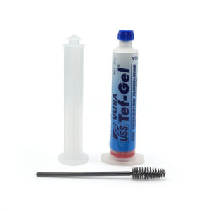
You can find more information about preventing galvanic corrosion in our Fighting Galvanic Corrosion with Zinc and Tef-Gel guide.
Parts and Tools Required for Assembly
You will also need the following tools:
- 1.5 mm hex key to install locking cord handles
- 2.5 mm hex key to install rubber feet
- 4 mm hex key to install lid handles (5L box only)
- M10 Bulkhead Wrench or 16 mm wrench to install bulkheads
- A pair of scissors or flush cutters
Assembling the Box
1. Four rubber feet are included with the box. To install the feet, use a 2.5 mm hex key and the included M3x8 socket head screws to secure them to the four corners on the bottom of the box.
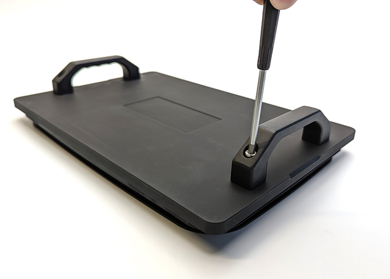
2. The 5 liter Watertight Box includes two lid handles (the 1 liter box does not use handles). To install the lid handles, use a 4 mm hex key and the included M5x20 socket head screws to secure the handles to the lid.
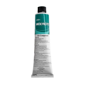
3. Inspect the inner sealing surface of the box to make sure it is clean and free of scratches or other damage. Apply an even layer of silicone grease to the inside sealing surface of the box.
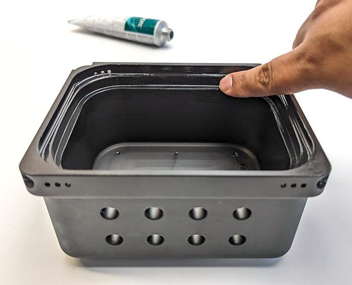
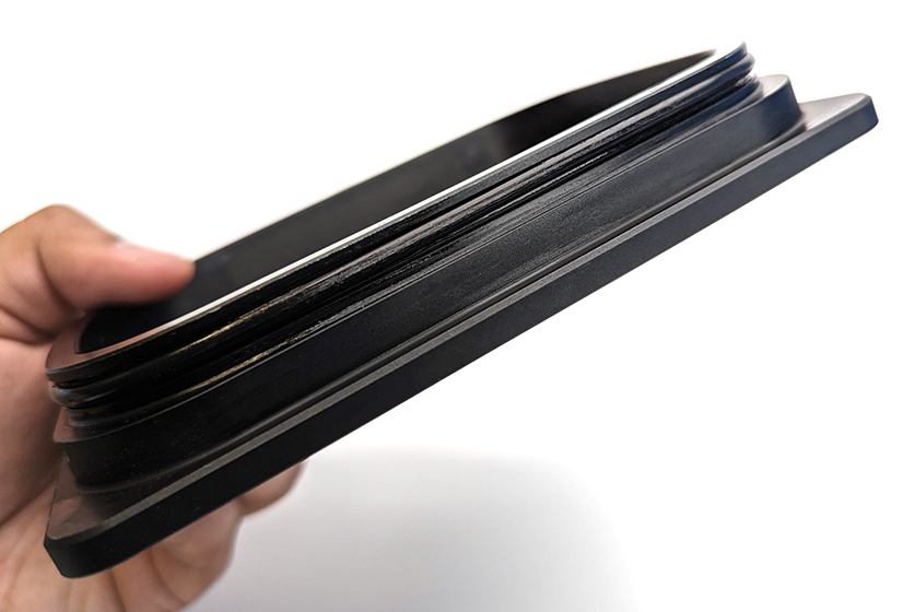
4. Inspect the O-ring and the O-ring groove in the lid to make sure they are clean and free of scratches or other damage. Apply an even layer of silicone grease to the lid O-ring and install it in the O-ring groove.
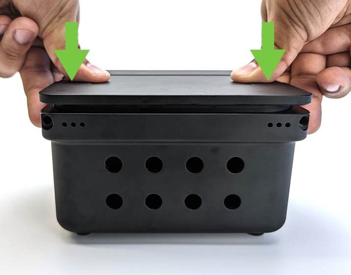
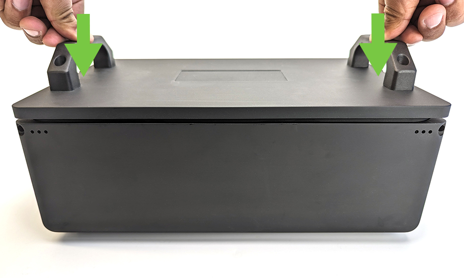
5. Place the lid on top of the box. Ensure the lid is level then push down evenly on both sides of the lid.
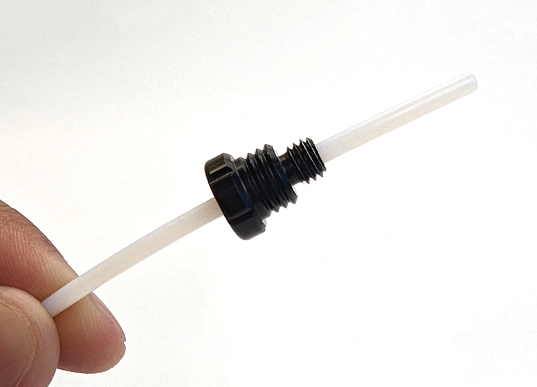
6. Take the included length of locking cord and put it through the locking cord handle.
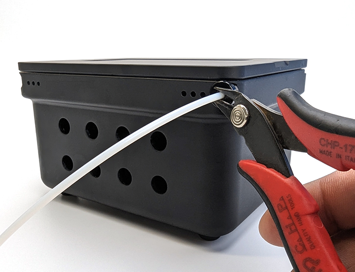
7. Insert the locking cord into the hole then thread the handle into the hole. Feed the locking cord through the hole until it just reaches the other side. Use your scissors or flush cutters to cut the locking cord at the handle to length.
8. Remove the locking cord and handle then use the small set screw and 1.5 mm hex key to lock the cord in place. Do not tighten the set screw too much as it will start to cut through the locking cord.
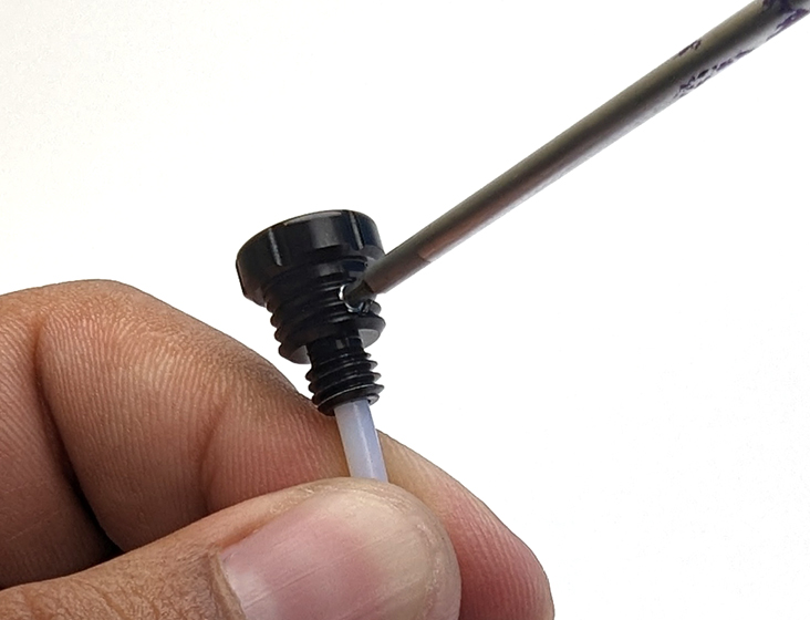
Repeat steps 7 and 8 for the other side.
Your Watertight Box is now assembled! Remove the locking cords and lid to proceed to installing your bulkhead penetrators.
Installing a Bulkhead Penetrator
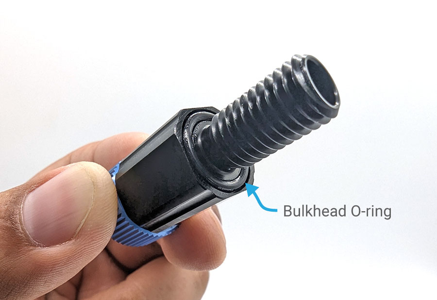
1. Inspect the bulkhead O-ring to make sure it is not dirty or damaged.
2. Lubricate the bulkhead O-ring with a thin layer of silicone grease and install it in the groove on the underside of the bulkhead.
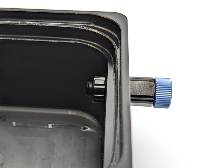
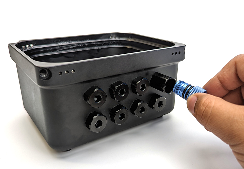
3. Insert the bulkhead through the hole and fasten a penetrator nut on the other side. Tighten the nut and bulkhead by hand until the bulkhead is held in place.
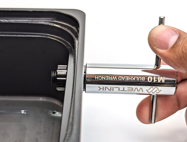
4. Use an M10 Bulkhead Wrench or 16 mm wrench to fully tighten the bulkhead. The Bulkhead Wrench can be used to tighten either the bulkhead side or the nut side. The bulkhead will no longer rotate in the hole when installed properly. If the bulkhead cannot be loosened using your fingers, it is tight enough.
Using Blank Penetrators
After installing all of your bulkheads, seal any unused holes in the box with an M10 penetrator blank.
Using WetLink Bulkhead Adapters
WetLink Bulkhead Adapters can be used to install a bulkhead into a hole that is too large.
Vacuum Testing the Box
We strongly recommend performing a vacuum test on all newly assembled Watertight Boxes or whenever you install or remove a bulkhead. Check out the guide below for instructions on how to use the hand-operated vacuum pump kit to test your box.
Using the Vacuum Plug and Hand Pump
Opening and Closing the Box
Closing the Box
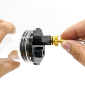
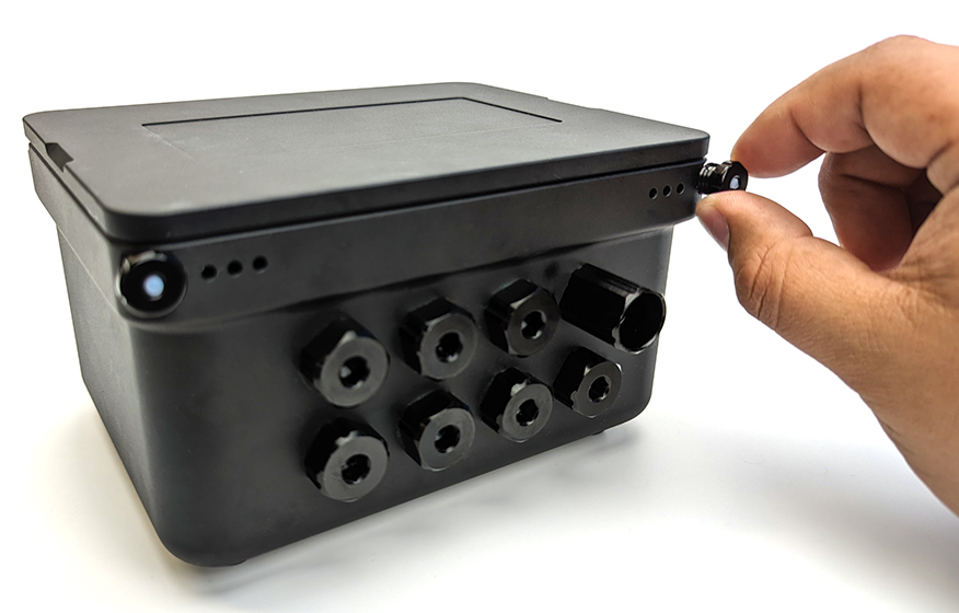
1. Remove the Pressure Relief Valve plug from the bulkhead.
2. Inspect the inner sealing surface of the box and the O-ring to make sure they are clean and free of scratches or other damage. Both the O-ring and the inner sealing surface should be adequately lubricated with silicone grease.
3. Place the lid on top of the box. Ensure the lid is level then push down evenly on both sides of the lid.
4. Insert the locking cords into the locking cord holes. The locking cord handles can be threaded into the holes to lock them in place.
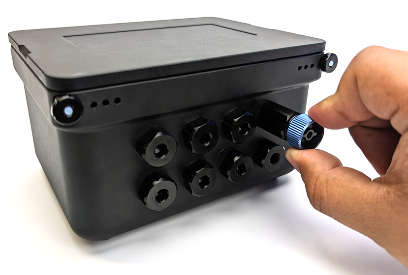
5. Install the Pressure Relief Valve plug in the bulkhead to seal the box.
Opening the Box
1. Remove the Pressure Relief Valve plug from the bulkhead.
2. If the cord handles are locked in, turn them counterclockwise to unthread them from the hole then pull out the locking cord.
3. Dry the exterior of the box and drain the water from the area around the lid to ensure water from outside does not drip inside while opening the lid. The following are some tips to help prevent water from dripping inside the box.
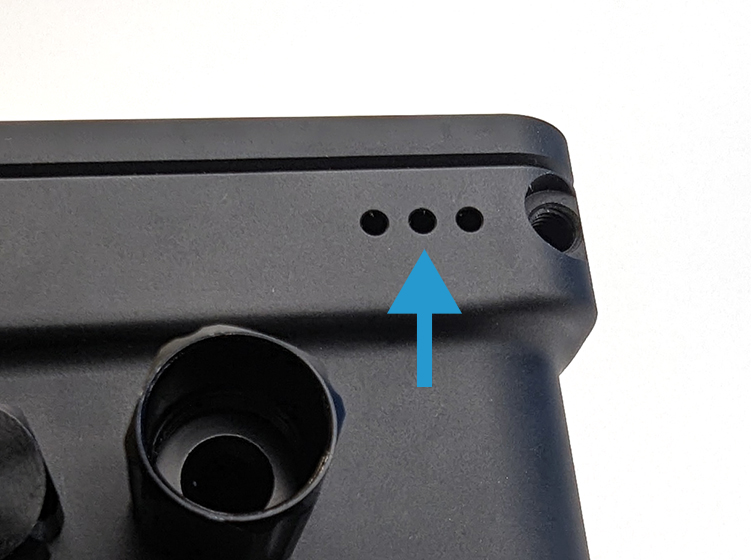
- Tilt the box on its side towards the drainage holes to allow the water to drain.
- Open the box while it’s tilted on its side so water does not fall directly into the box.
- Blow compressed air through the drainage holes to blow out any water from the area between the box and the lid.
If removing the lid is difficult, you can use the Watertight Enclosure Pry Tool. Insert the pry tool into the slot under the lid then give it a twist to separate the lid from the box.
Removing a Bulkhead
Use a Bulkhead Wrench to turn the bulkhead or nut counterclockwise until it is loose enough to remove by hand.
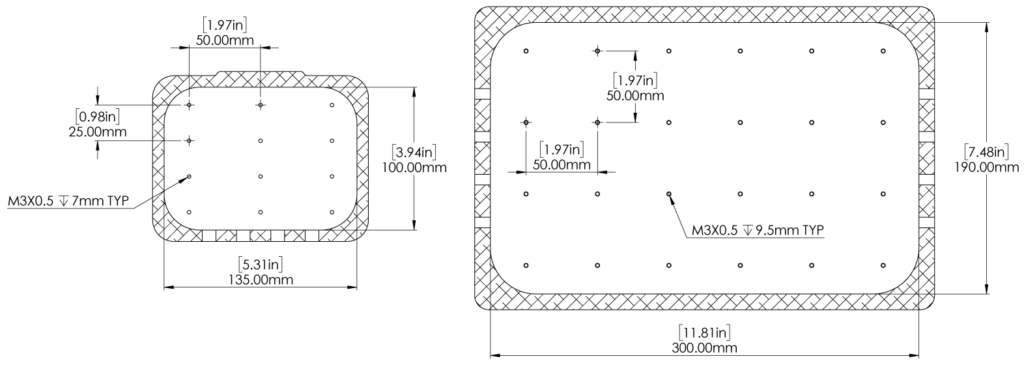
Mounting Components Inside the Box
The boxes feature M3x0.5 threaded holes inside the box to mount components. The 1L box mounting holes are in a 25 mm by 50 mm grid pattern and the 5L box mounting holes are in a 50 mm by 50 mm grid pattern. The mounting hole patterns are shown below.
When mounting electronic components, avoid shorts by electrically isolating the component from the box by using standoffs or nonconductive mounting bracket. We designed a few 3D printable mounts for popular microcontrollers to help get you started:
Avoid electrically grounding components directly to the box. Directly grounding to the aluminum case in a salty or wet environment can accelerate corrosion.
Another cool thing about the boxes is that they make excellent heatsinks! Using thermally conductive silicone pads is a great way to heatsink hot components to the case while also keeping them electrically isolated.
Mounting the Box
The boxes have external threaded holes for mounting.
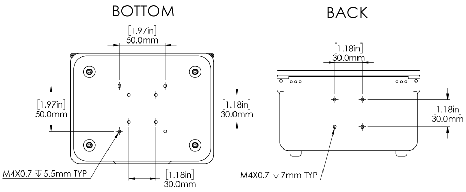
1L Box
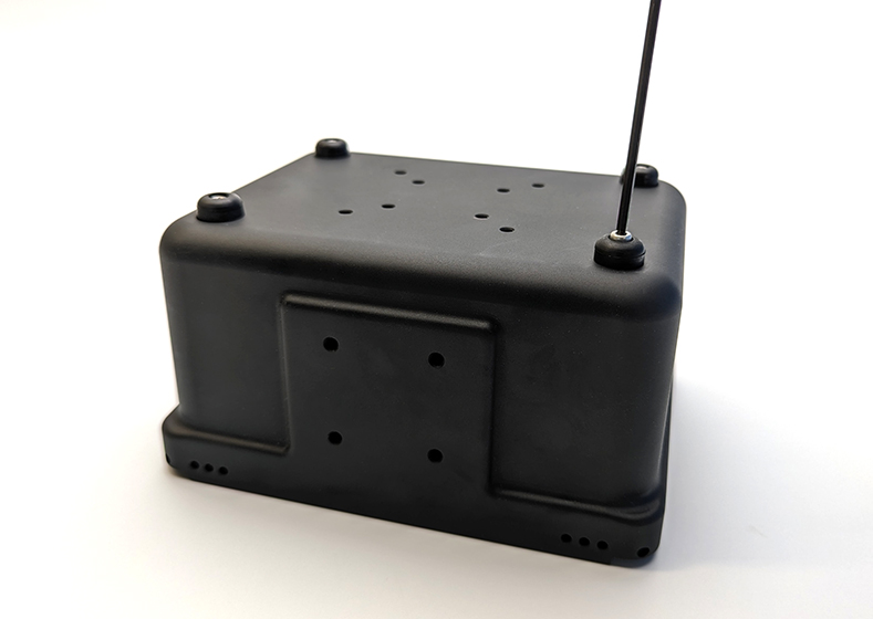
The 1 liter box has M4x0.7 mounting holes on the bottom and back of the box. The mounting pattern is shown below.
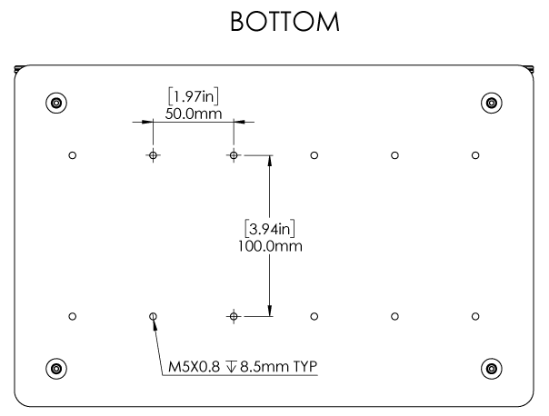
5L Box
The 5 liter box has M5x0.8 mounting holes on the bottom of the box. The mounting hole pattern is shown below.
Maintenance
- Rinse the box well with freshwater after use in saltwater.
- Never use strong cleaners such as acids, bases, solvents or abrasives to clean the box. Plain water or a mild detergent is usually enough to clean the box if necessary.
- Check the lid O-ring whenever you open or service the box. Replace the O-ring if it is damaged. Replacement O-rings are available here.
- Relubricate the sealing surface of the box and the lid O-ring with silicone grease if the lid becomes difficult to remove.
- Relubricate the Pressure Relief Valve plug O-rings with silicone grease if it becomes difficult to remove.

Drilling Holes
Do you need more holes, or different sized holes? Just drill some more! Additional holes can be drilled into the sides of the box, just be careful not to drill into the lid sealing interface; a good idea is to drill new holes at around the same height as the existing holes. Only drill holes through the sides of the box, do not drill holes through the lid or bottom of the box. Use a 10 mm drill bit to make holes for M10 bulkheads or a 14 mm drill bit for M14 bulkheads. You can also drill out an existing M10 hole to accommodate an M14 bulkhead.
Installing Micro Circular Wet-Mateable Connectors
The standard thread for most Subconn and Seacon type Micro Circular connectors is 7/16″-20. The existing M10 holes can be tapped with a 7/16″-20 tap to make the proper threads.
Feedback
We’re always working to make our documentation, instructions, software, and user experience even better. If you have any ideas on how we can improve this guide, feel free to let us know here.