
Using a Newton Subsea Gripper with an Arduino
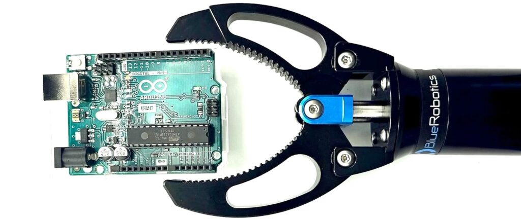
This guide shows how to power and control a Newton Subsea Gripper using an Arduino. The gripper uses a standard RC-style PWM control signal and requires a separate power supply.
This is an example setup only. You are not required to use the same Arduino model, PWM pin, power source, wiring method, or terminal hardware shown here. Adjust as needed to match your system architecture and available components.
Parts and Tools
You Will Need
To complete the installation, you will also need the following tools (not included):
Required
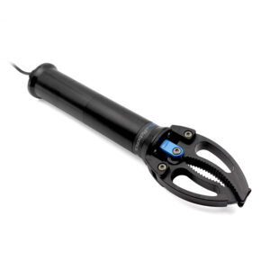
- Arduino Uno (used in this example)
- External DC power source, 9–18 VDC (Lithium-ion Battery used in this example)
- Jumper Wires
Optional / Example Hardware
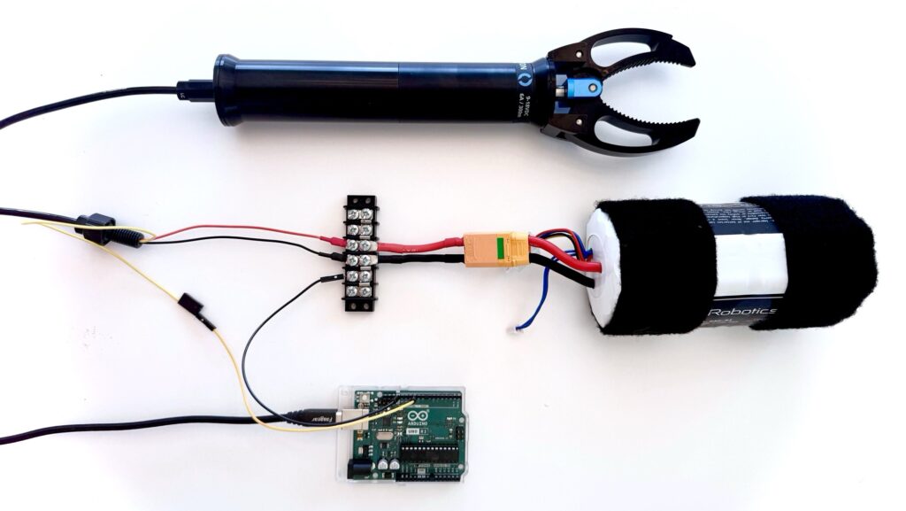
Connecting the Newton Gripper to the Arduino
This guide uses an Arduino Uno and digital pin 10 for the PWM signal. Other Arduino boards and digital pins may also be used, provided they support standard servo-style PWM output.
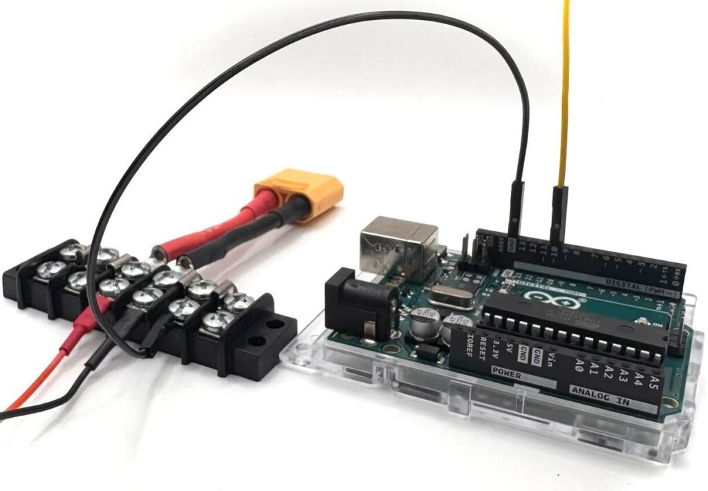
1. Connect the M6 spade fork terminals to the terminal block.
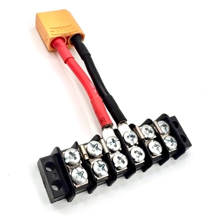
2. From the terminal block:
- Connect the red (positive) wire from the gripper to the positive side terminal block.
- Connect the black (ground) wire from the gripper to the negative side terminal block.
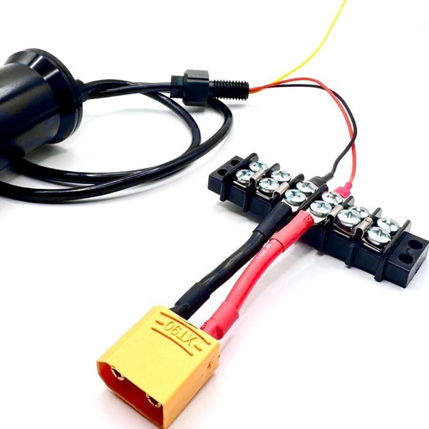
4. Using a Jumper wire, connect the Gripper’s yellow signal wire to Arduino digital pin 10, and connect the Arduino GND to the terminal block.
The Arduino ground and gripper power supply ground must be connected. A shared ground is required for a proper PWM signal reference; without a common ground, the gripper may not respond or may behave unpredictably
5. Power on the System.
- Verify all wiring connections are secure and polarity is correct.
- Connect the Arduino to your computer via USB.
- Apply power to the gripper motor supply by connecting the female XT90 connector from the Lithium-ion Battery (14.8V, 18Ah) to the male XT90 connector from the terminal block.
Arduino Code
This example uses the Arduino Servo library to generate the PWM signal.
In the code below:
- OPEN_TIME and CLOSE_TIME control how long the gripper is commanded to move. These values are in seconds and can be adjusted as needed.
- OPEN_PWM_US and CLOSE_PWM_US define the PWM command sent to the gripper. These values set the open and closed commands.
The typical control range for the Newton Subsea Gripper is approximately 1100 µs to 1900 µs. Values outside this range may not result in additional motion and should be tested carefully.
Example code for Arduino is shown below.
#include "Servo.h"

#define GRIPPER_PWM_PIN   10    // Gripper PWM output pin
#define OPEN_TIME         5.0   // Gripper open time (seconds)
#define CLOSE_TIME        5.0   // Gripper close time (seconds)

#define OPEN_PWM_US       1100  // Gripper open PWM output (us)
#define CLOSE_PWM_US      1900  // Gripper close PWM output (us)

Servo gripper;

void setup() {
  // Attach gripper to proper pin
  gripper.attach(GRIPPER_PWM_PIN);

}

void loop() {
  // Open the gripper
  gripper.writeMicroseconds(OPEN_PWM_US);

  // Let the gripper open up (microseconds)
  delay(OPEN_TIME*1000);

  // Close the gripper
  gripper.writeMicroseconds(CLOSE_PWM_US);

  // Let the gripper close for a while (microseconds)
  delay(CLOSE_TIME*1000);
}
Using Other Arduino Boards
If you are using a different Arduino model:
- Any digital pin capable of servo-style PWM output may be used
- Update the PWM pin definition in the code to match your wiring
- Ensure the Arduino ground is connected to the gripper power supply ground
Help and Feedback
If you need help using the Newton Subsea Gripper, reach out to our support team using our help center.
We’re always working to make our guides, software, and user experience even better. If you have any ideas on how we can improve this guide, feel free to let us know here.