Fathom Spool Assembly
Introduction
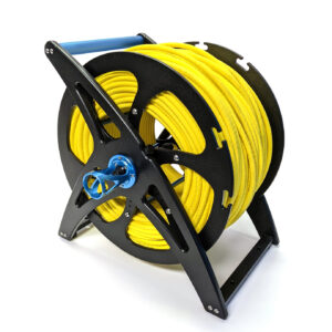
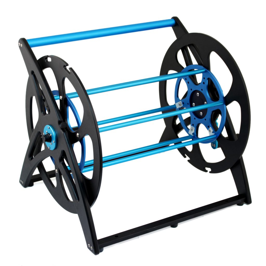
The Fathom Spool is a rugged and easy to use spool that simplifies tether storage and management for your BlueROV2! Full IP67 water resistance, 8-wire slip-ring, and integrated quick connectors make it tough enough to use at almost any dive site while remaining easy to transport.
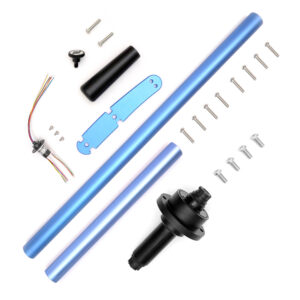
Parts and Tools
You Will Need
- 1 x #1 Phillips head screwdriver
- 1 x #2 Phillips head screwdriver
- 1 x 2.5 Hex key or driver (one is included in BlueROV2 kit)
- 2 x 3.0 Hex key or driver (one is included in BlueROV2 kit, additional sets are available here)
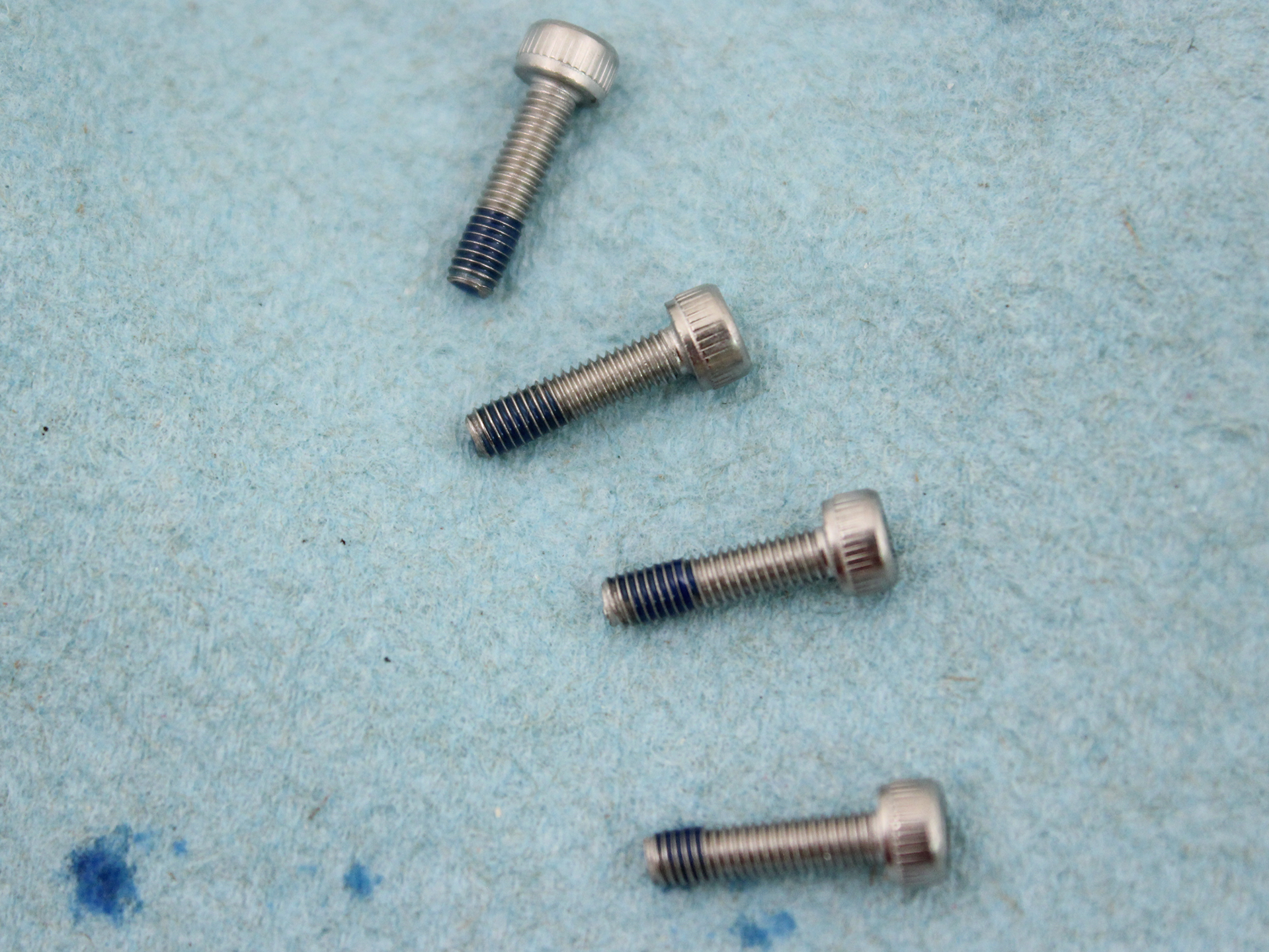
- 1 x Medium-strength (blue) thread locker such as Loctite 243. All machine threaded screws must have thread locker applied during assembly.
Required Thread Locker Application
Assembly
The Fathom Spool kit comes flat packed and requires about one hour of assembly time. The assembly can be completed with basic hand tools; no soldering or potting is required. Unless otherwise indicated, all machine threaded screws must have thread locker applied during assembly.
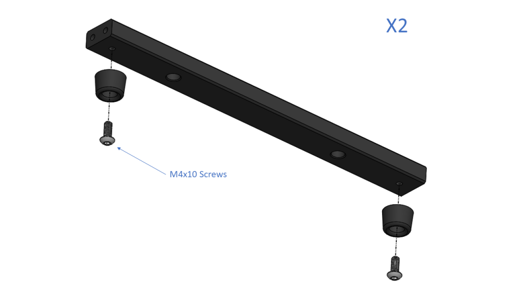
Assembling the Feet
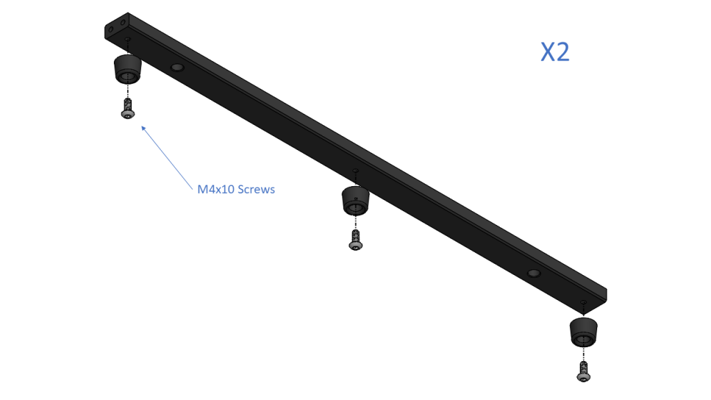
For the standard version, with a 2.5 mm hex driver use two threadlocked M4x10 screws to attach two rubber feet to the bottom of each frame foot. Repeat to make two units.
Standard Spool
For the large version, with a 2.5 mm hex driver use three threadlocked M4x10 screws to attach three rubber feet to the bottom of each frame foot.
Large Spool
Assembling the First Frame Half
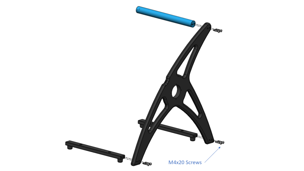
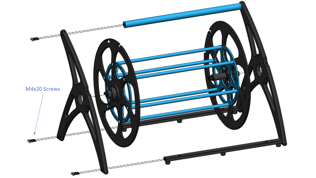
Using six threadlocked M4x20 screws and a 2.5 mm hex driver, screw the two feet and single frame handle to the same side of a side panel, rubber feet point down. Tighten the screws until they indent the plastic slightly. Note the round handle goes to the rounded tip at the top of the frame.
Standard Spool
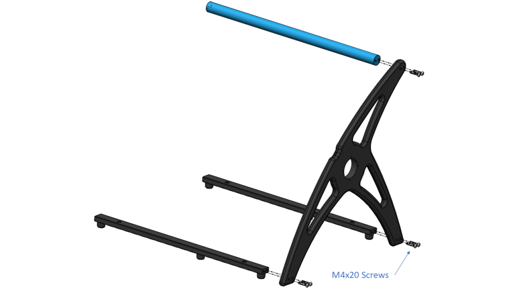
Large Spool
Attaching the Slip Ring Core to the First Flange
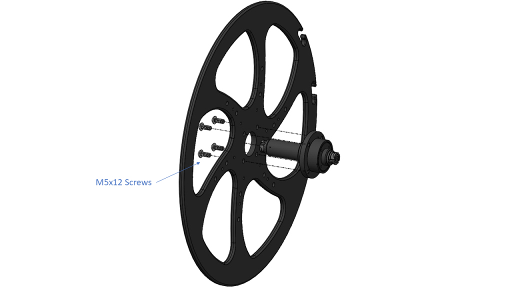
Use four threadlocked M5x12 screws and a 3.0 mm hex driver to attach the slip ring core to a flange. Note the screw heads come through the plastic flange to screw into the aluminum slip ring core, and the long end of the core should be passed through the central hole in the flange. Tighten the screws until they indent the plastic slightly.
Adding the Spool Standoffs
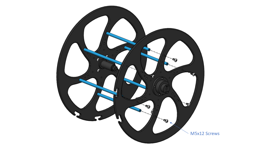
For the standard version, use six threadlocked M5x12 screws and a 3.0 mm hex driver to secure the six spool standoffs to the outermost holes on the inside face of the spool, facing the same direction as the long end of the core. Tighten the screws until they indent the plastic slightly.
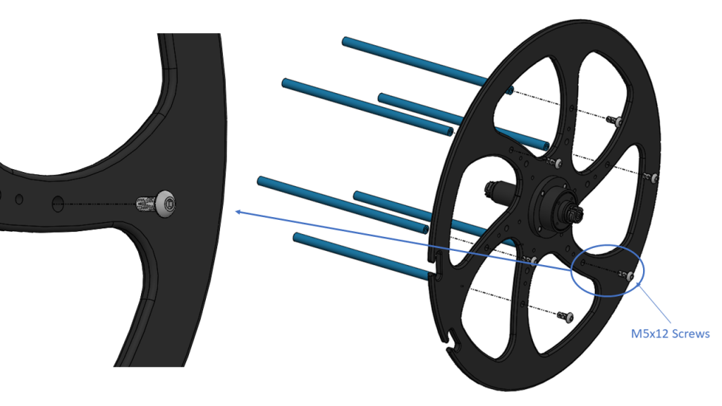
Standard Spool
For the large version, use six threadlocked M5x16 screws instead and a 3.0 mm hex driver to secure the six spool standoffs and one stiffening ring, with the stiffening ring placed between the standoffs and the spool face. Match the stiffening ring cutout pattern to the spool face. Tighten the screws until they indent the plastic slightly.
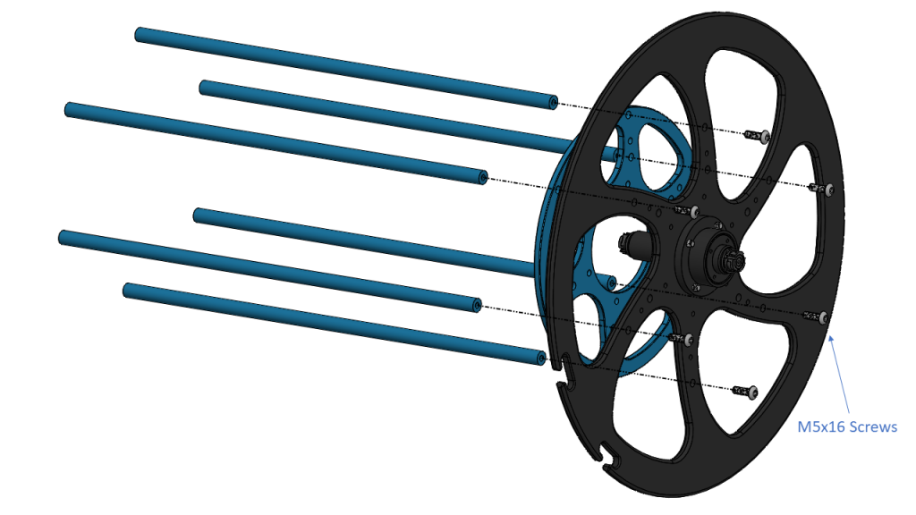
Large Spool
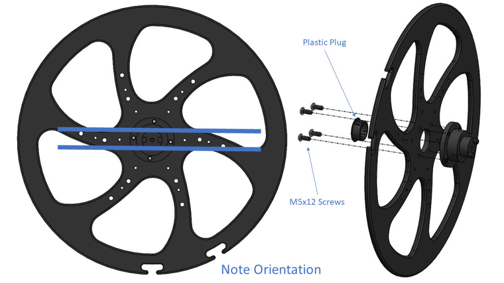
Attaching the Crank Arm Hub to the Second Flange
Using four threadlocked M5x12 screws and a 3.0 mm hex driver, secure the crank arm hub to the second flange. Note the screw heads come through the plastic flange to screw into the aluminum crank arm hub, and the short end of the core should be passed through the central hole in the flange. The two teeth on the crank arm hub should line up with two splines on the flange. If they do not, rotate 90° and secure. In addition, the flange should be oriented with the splines curving as shown. Press the black plastic plug in the hole in the crank arm hub. Tighten the screws until they indent the plastic slightly.
Adding the Tether Securing Clips
For the standard version, use three #8-1/4″ self tapping screws and a #2 Phillips head driver to secure three nylon clamps to the inside face of the flange where the plug is located. The clamps should be mounted next to each other in the second from outermost holes.
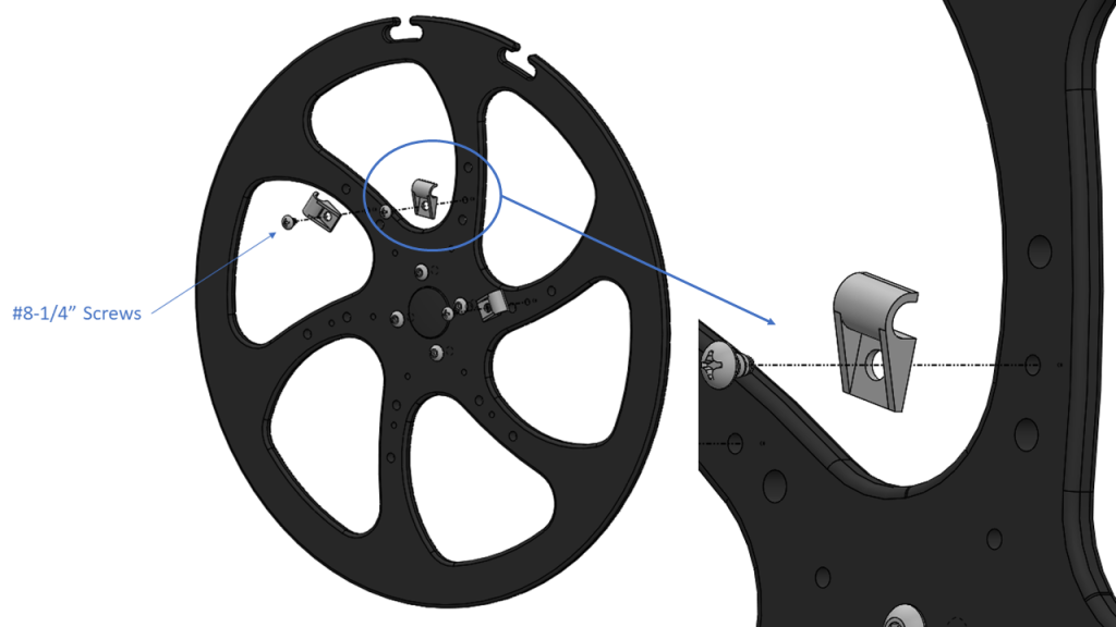
Standard Spool
For the large version, use three #8-1/2″ self tapping screws instead and a #2 Phillips head driver to secure the clips against the face of the stiffening ring. Match the stiffening ring cutout pattern to the spool face.
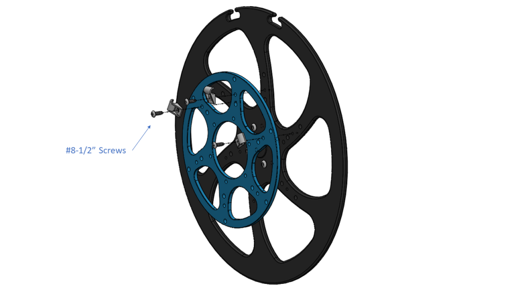
Large Spool
Combining the Flanges
Attach the two flanges to each other with six threadlocked M5x12 screws, locating the standoffs in the outermost ring of holes. Use two 3.0mm hex drivers, one on each side of the assembly, to tighten each pair of screws per standoff in sequence. Tighten the screws until they indent the plastic slightly.
Standard Spool
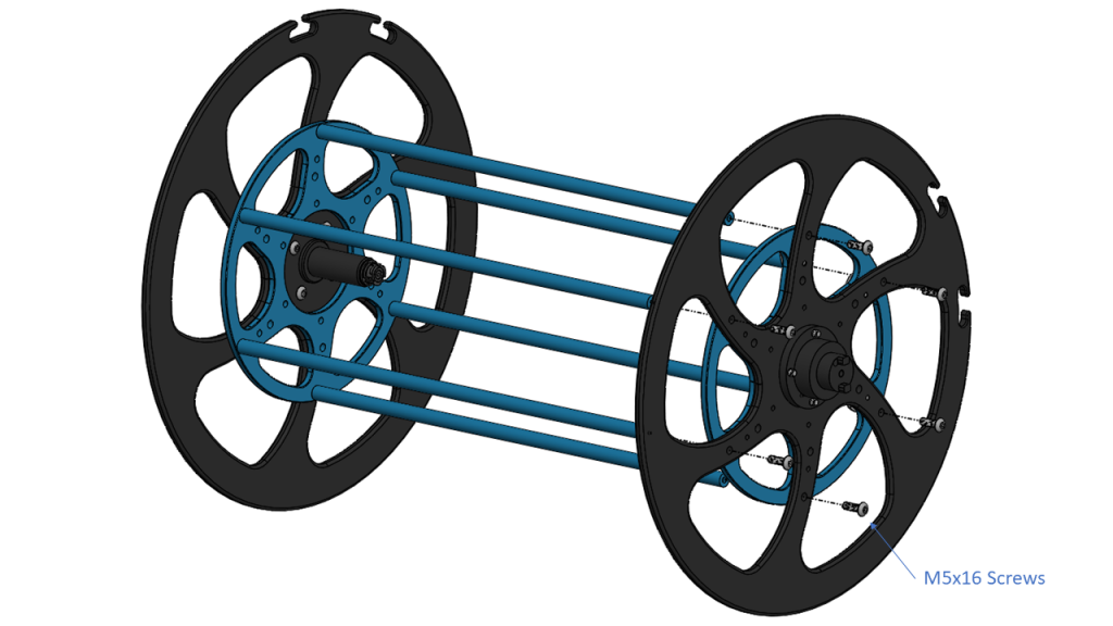
Large Spool
Completing the Frame
Mount the spool assembly to the partially assembled first frame half, and then use six threadlocked M4x20 screws and a 2.5 mm hex driver to capture the assembly by completing the frame with the second frame panel. The spool assembly can be mounted in either orientation so that the crank handle can be on either side according to personal preference. Pictured is the left handed cranking orientation. Note the round handle goes to the rounded tip at the top of the frame. Tighten the screws until they indent the plastic slightly.
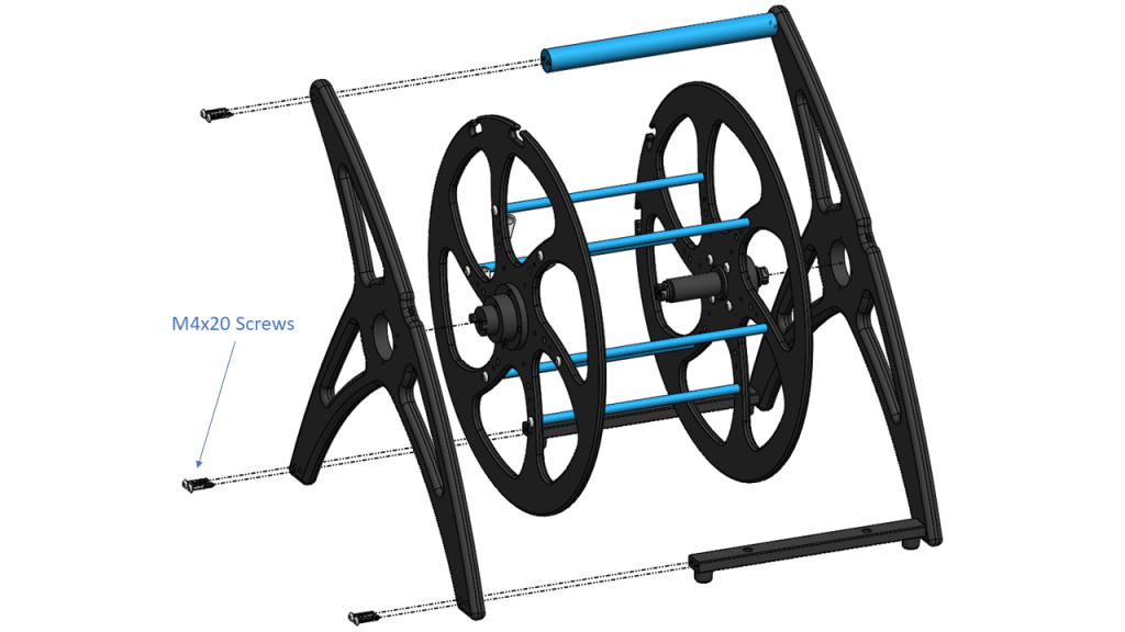
Standard Spool
Large Spool
Securing the Slip Ring Core
You have the option of securing the slip ring core using either the Fathom Spool Connector Guard or the slip ring cap flange. The Fathom Spool Connector Guard protects the binder bulkhead connector against accidental damage from tipping over or strain on the extension cable. We recommend the Fathom Spool Connector Guard be installed whenever possible. Otherwise, the slip ring cap flange can be used if it is preferred to keep the spool more compact.
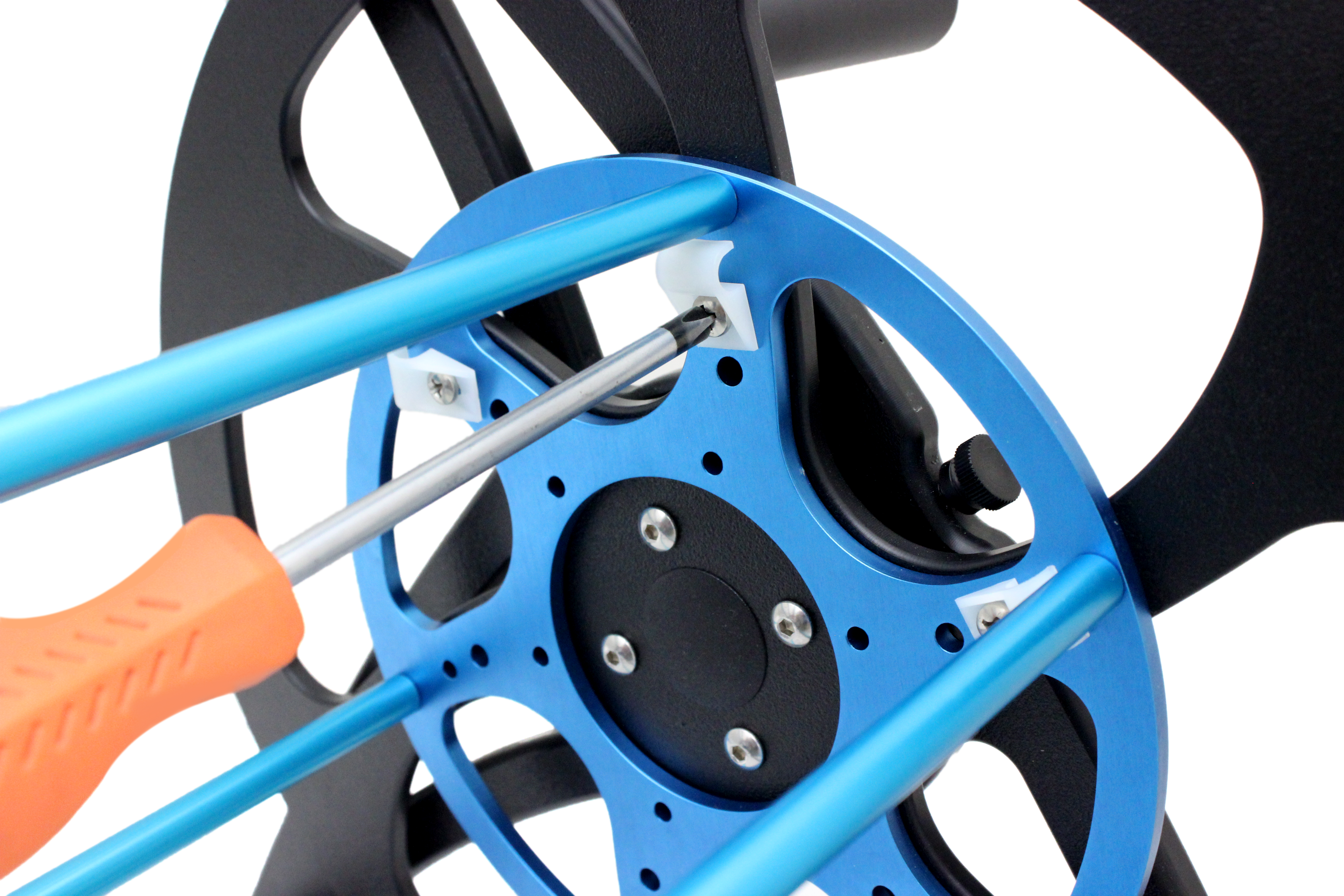
Secure the slip ring core with either the Fathom Spool Connector Guard or slip ring cap flange. Use a #1 Phillips head driver to secure the four #4-5/8″ self tapping screws through the outer set of screw holes and into the plastic frame. Use a 2 mm hex driver to secure the four threadlocked M3x6 screws through the inner set of screw holes into the aluminum slip ring core. The slip ring core should be oriented such that the white strip on the Binder 770 connector faces up as much as possible.
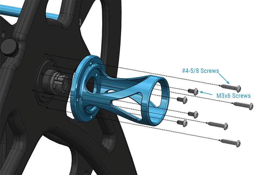
Installation of the Fathom Spool Connector Guard.
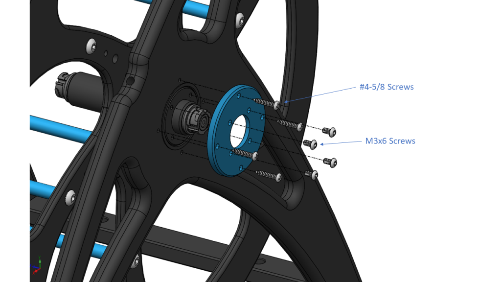
Installation of slip ring cap flange.
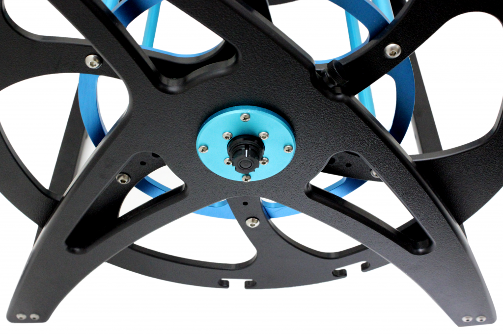
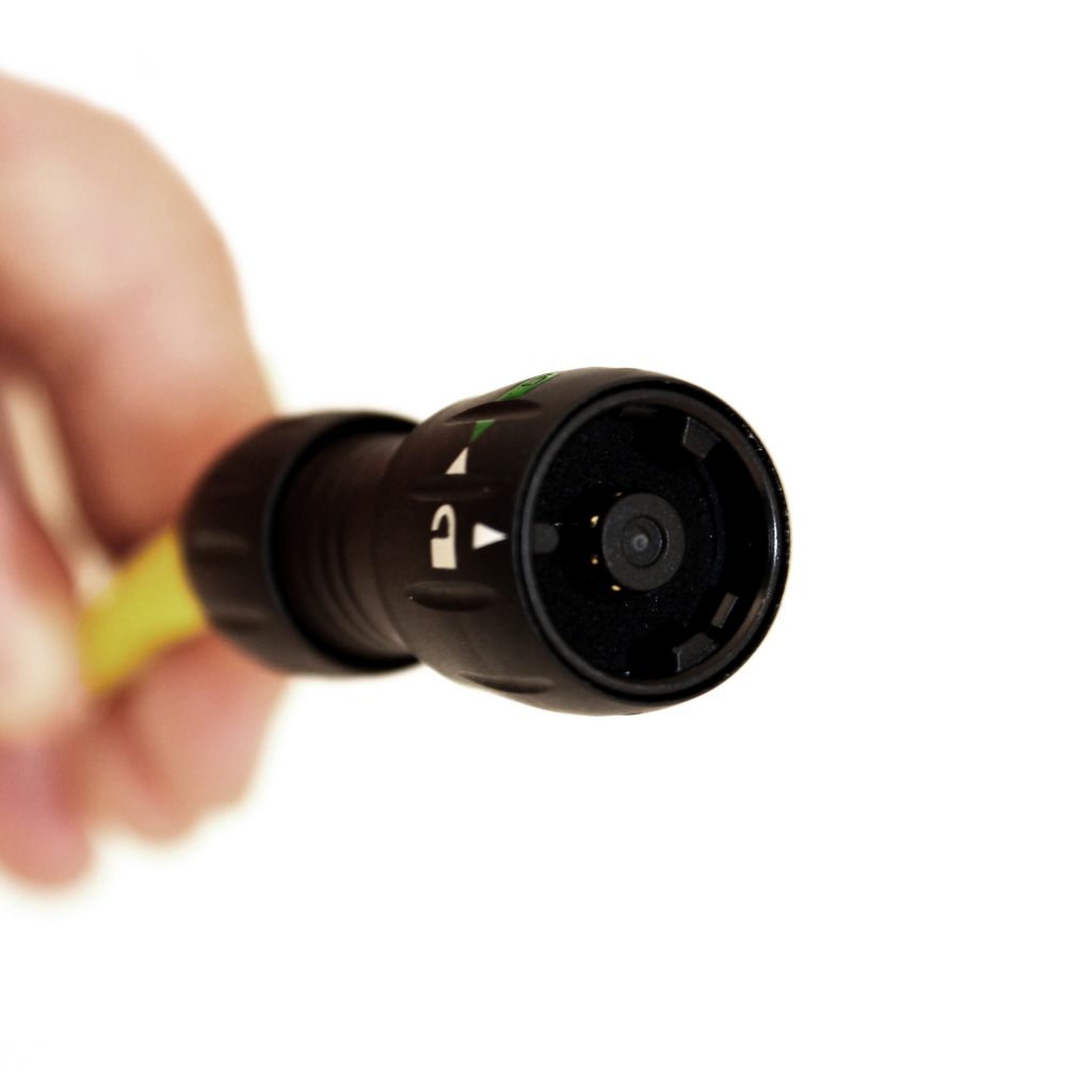
Binder 770 bulkhead connector with the white strip facing up.
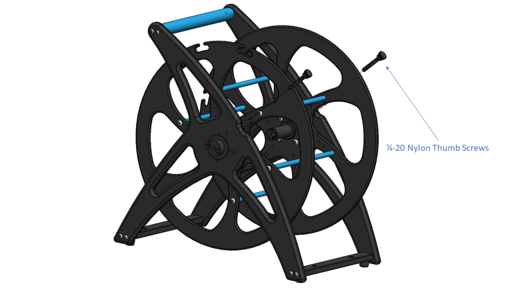
Adding the Braking Thumbscrews
Screw two 1/4″-20 nylon thumbscrews all the way down into the threaded holes in the center of the long edge of each of the frame panels, then back off one half turn.
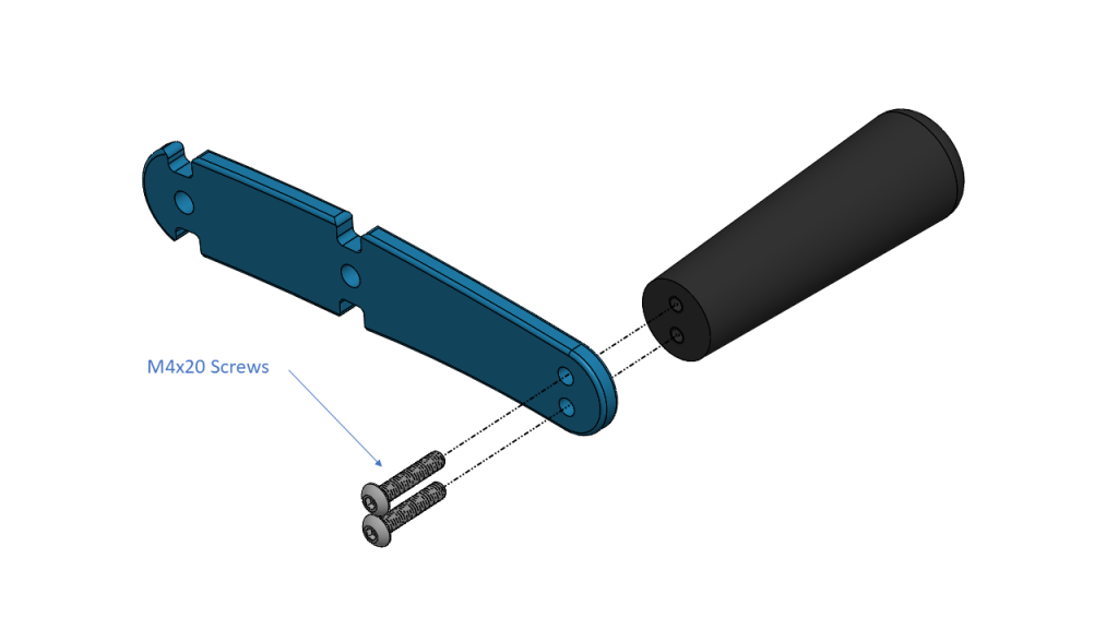
Assembling the Crank
Use two M4x20 screws and a 2.5 mm hex driver to secure the crank handle to the crank arm. The crank arm can curve to either direction according to aesthetic preference. DO NOT use threadlocker.
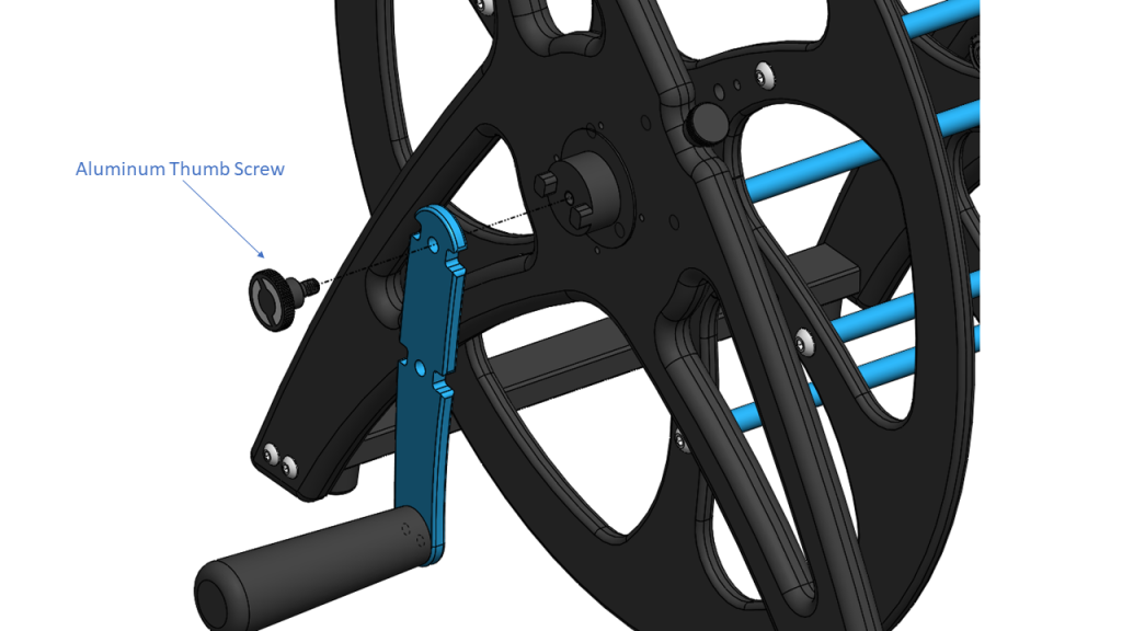
Attaching the Crank
Use the aluminum thumbscrew to attach the crank to the crank hub to complete your Fathom Spool. No threadlock is needed, the thumbscrew is designed to be removeable.
Mounting the Tether
A Binder 770 connector is required on the topside end of your tether to enable use with the Fathom Spool. If your tether does not have a Binder 770 connector installed, refer to the Binder 770 Installation Tutorial.
Preparing the Connector
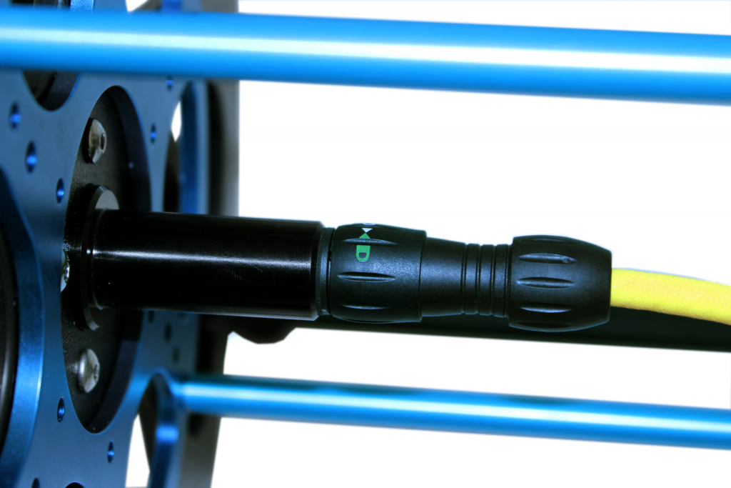
Rotate the locking collar on the tether Binder 770 connector to line up the white vertical arrow with the rounded tooth on the interior. This puts the connector in the unlocked position.
Loosening the Tether Clips
Loosen the three white tether retaining clips so they easily swing up.
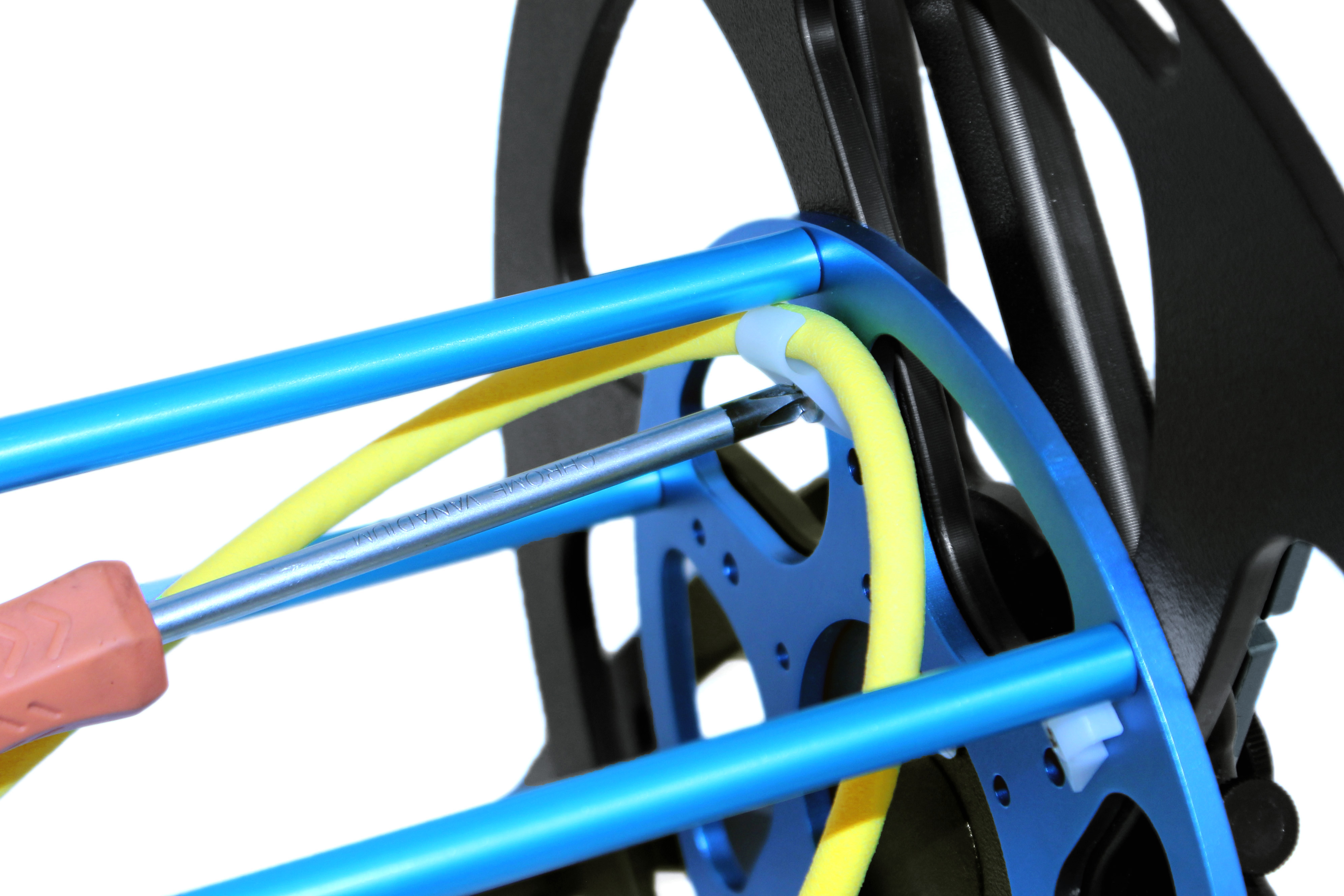
Guiding in the Tether
Pass the tether to the interior of the spool between two of the blue standoffs just ahead of the tether retaining clips.
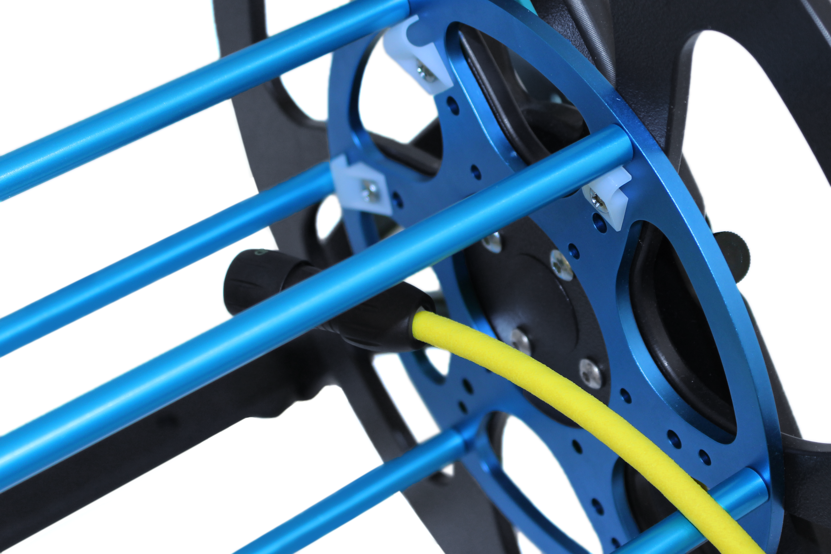
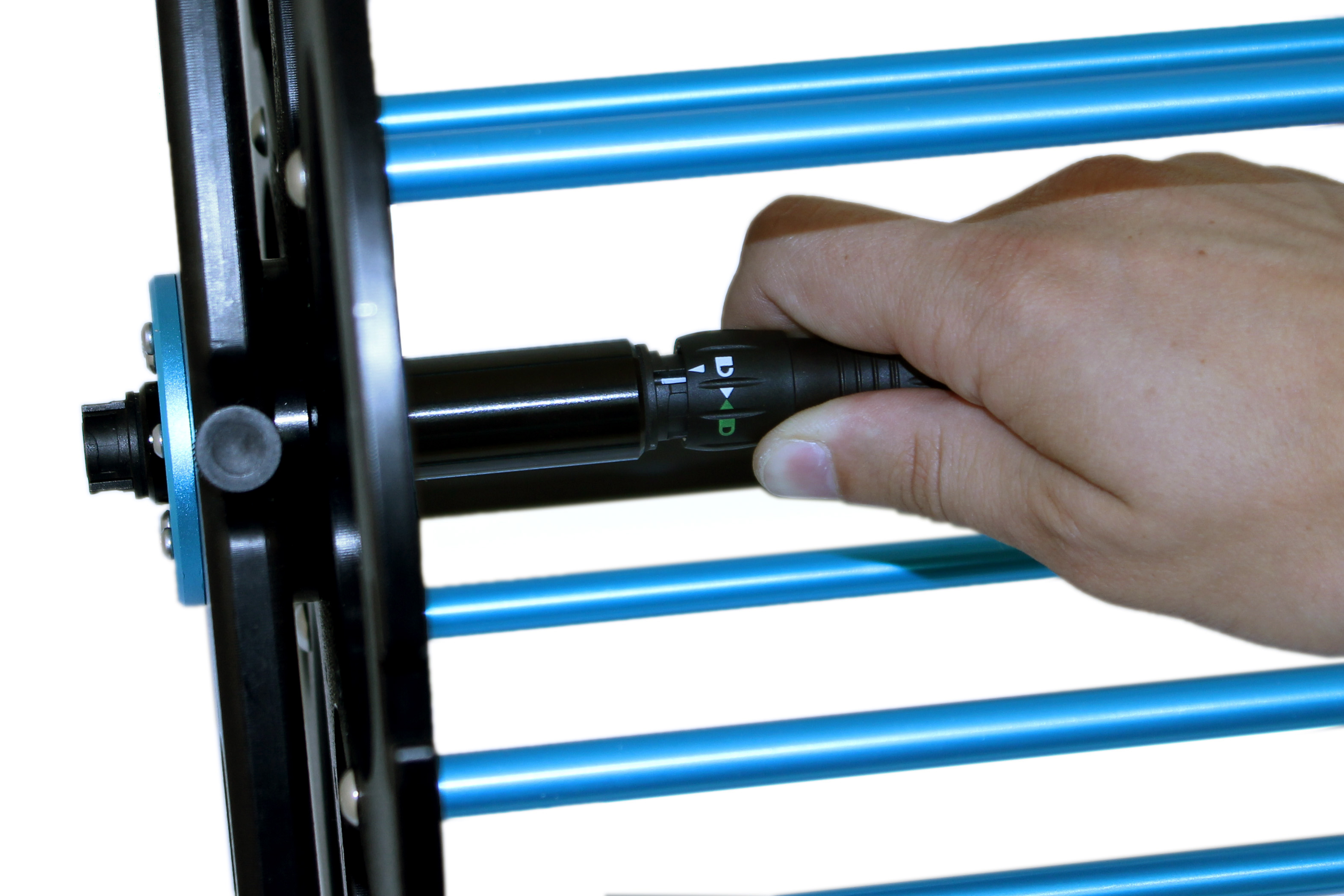
Securing the Connection
Connect the tether to the slip ring core, rotating the locking collar to lock the connector in place.
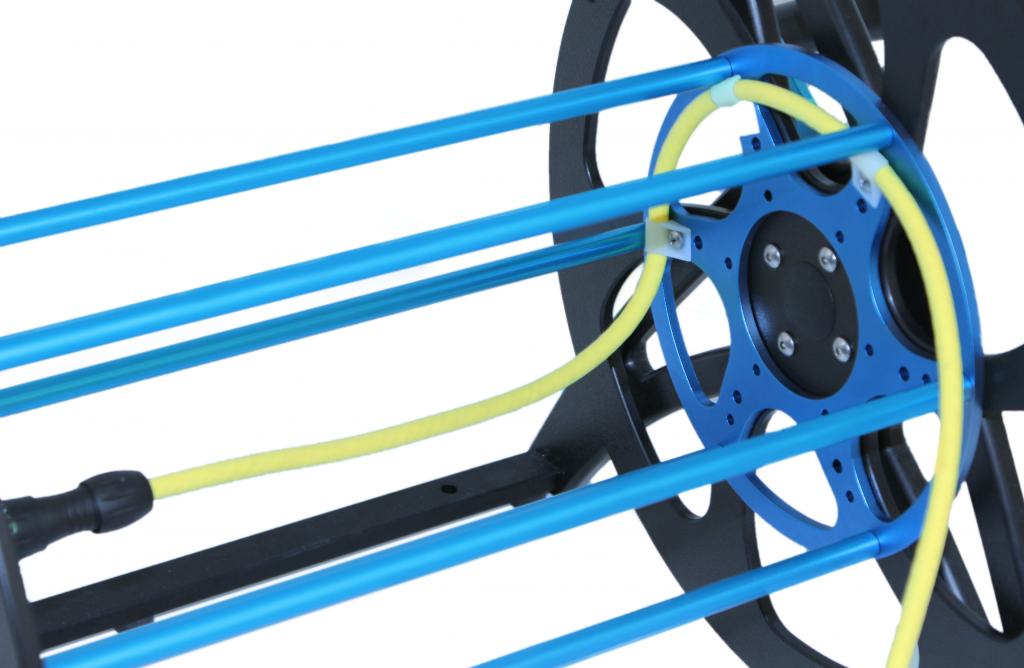
Securing the Tether
Feed the tether into each of the three retaining clips, keeping some slack in the cable where it goes to the connector. Re-tighten the retaining clips to secure the tether. If using Fathom Slim tether, loop the tether around each clip once in addition to passing it through for security.
Winding the Tether
Using one hand, crank the spool while using the other hand to keep the tether taut and feed it in evenly. Wind over the entire width of the spool before winding another layer to maximize space efficiency and neatness.

Maintenance
The Fathom Spool has a rugged design which does not require much maintenance.
After Every Use
Every 100 Hours of Operation or Every 6 Months
Check the operation and condition of the sealing x-ring in the slip ring core. If there is significant resistance or rough running, inspect with the following steps:
1. Loosen the connector on the outside of the unit to break the seal and open an air vent.
2. Remove the four #4-5/8″ self tapping screws around the perimeter of the blue slip ring cap flange.
3. The slip ring cap can now be pulled straight away from the unit, and the x-ring can be inspected for wear. If there is excessive wear it should be replaced. Re-grease if necessary.
4. Reverse the steps for reassembly, making sure to fully tuck the slip ring wires into the cap before replacing it to avoid pinching or cutting any wires.
Spare Parts
Spare replacement parts for the Fathom Spool can be found here.