
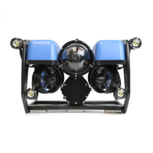
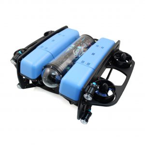
BlueROV2 Heavy Configuration Retrofit Kit Installation
Introduction
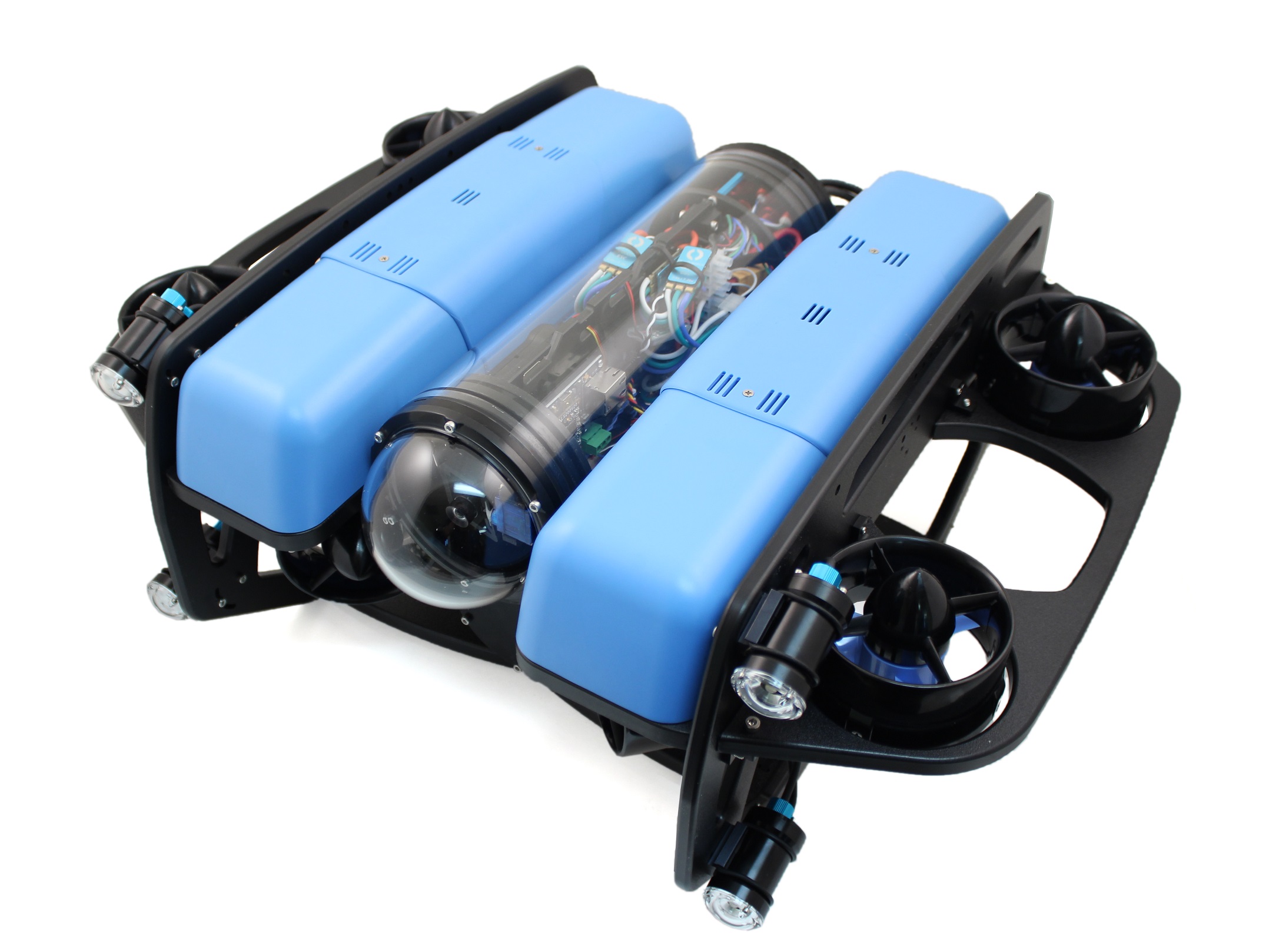
The BlueROV2 Heavy Configuration Retrofit Kit provides the components needed to upgrade your ROV to have four vertical thrusters, external thruster guards, and additional buoyancy. With that upgrade, you’ll gain 6 degree-of-freedom control and active stabilization in roll and pitch making the BlueROV2 Heavy the most stable but maneuverable mini ROV on the market.
This guide will guide you through the process of retrofitting the Heavy Configuration Retrofit Kit onto a fully assembled BlueROV2. If you are building a new BlueROV2 with a Heavy Configuration Retrofit Kit from scratch, please use the BlueROV2 Assembly Guide instead.
Parts and Tools
You Will Need
-
BlueROV2
Affordable and customizable high-performance ROVFrom: $ 4,900.00 -
BlueROV2 Heavy Kit
Add-on kit for improved stability and maneuverability$900.00 -
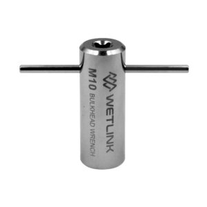
WetLink Bulkhead Wrench
For use with M06, M10 or M14 bulkheadsPrice range: $17.00 through $22.00 -
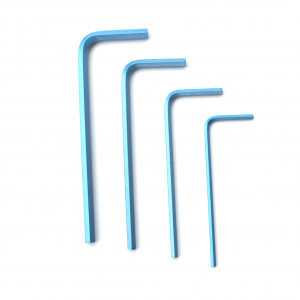
Hex Key Set
Commonly used on the BlueROV2 and other products$7.00
You will also need:
- 1 x #2 Phillips head screwdriver (BlueROV2 kit)
- 1 x Bottle of Threadlocker (not included)
BlueROV2 Partial Disassembly
To partially disassemble your BlueROV2, you will need the following tools:
- 1 x 2.5 mm hex driver
- 1 x #2 Phillips head screwdriver
- 1 x Wire cutters or scissors
- 1 x Penetrator wrench
- Optional: 1x Roll of masking tape and marker
1. To ensure your ROV is completely powered off, please remove the battery completely from the 3” enclosure and place to the side.
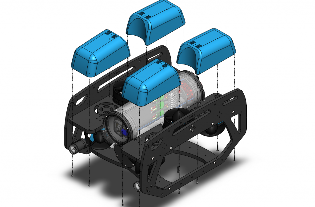
2. Remove the fairings and buoyancy blocks by removing the self-tapping screws that hold the fairings to the frame.
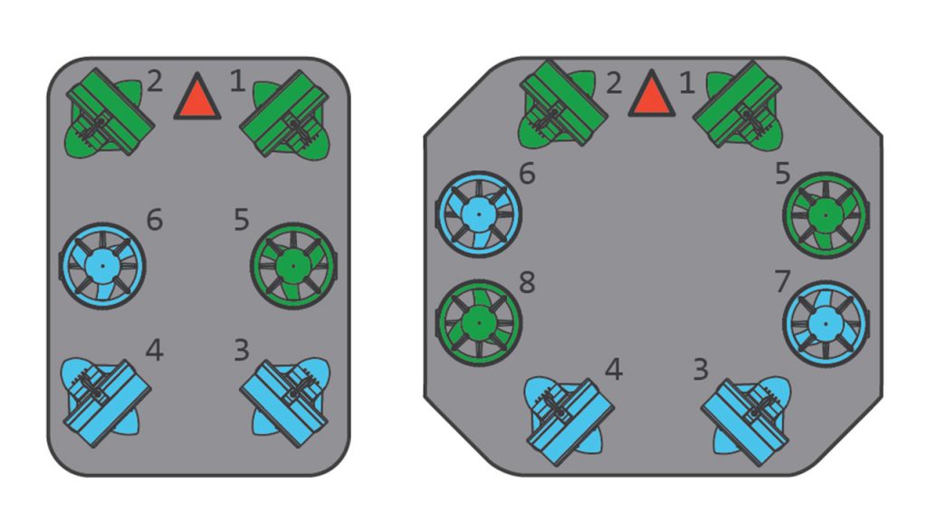
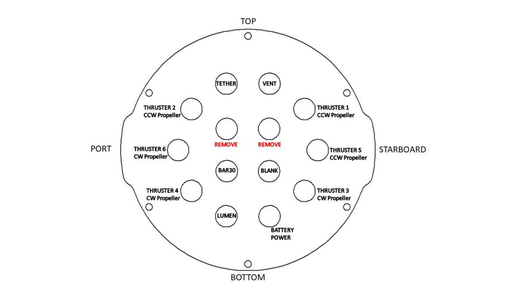
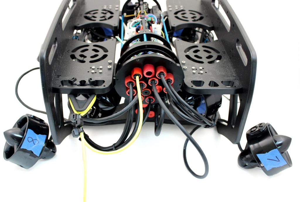
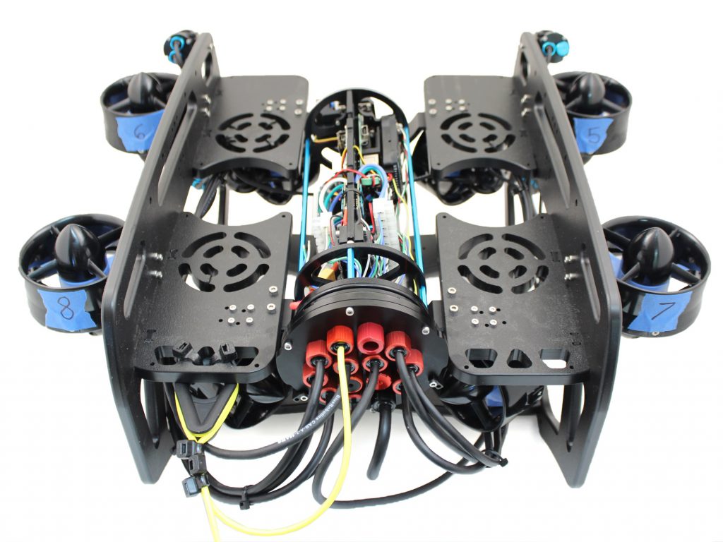
3. Optional: In order to ensure thruster mounting is not mixed up, it is recommended to apply short strips of masking tape to the outside of the thruster ducts and labeling them 5,6,7 and 8 respectively according to the thruster diagrams.
- Thruster 5 (CCW propeller) with red penetrator nut.
- Thruster 6 (CW propeller) with red penetrator nut.
- Thruster 7 (CW propeller) with red penetrator nut.
- Thruster 8 (CCW propeller) with red penetrator nut.
4. Remove the M3x12 screws holding Thrusters 5 and 6 to the side panels and place the screws to the side.
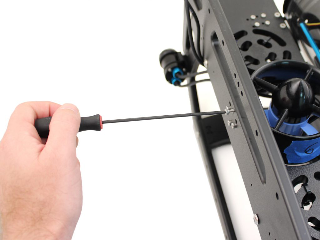
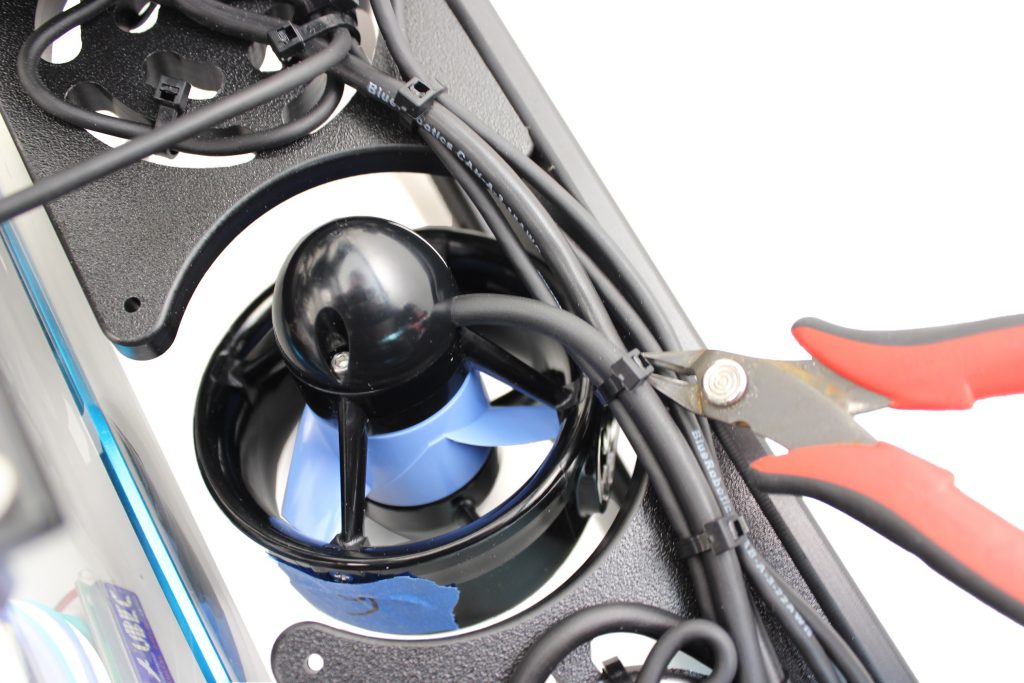
5. Cut and remove any zipties holding the motor wires for Thrusters 5 and 6 to the frame.
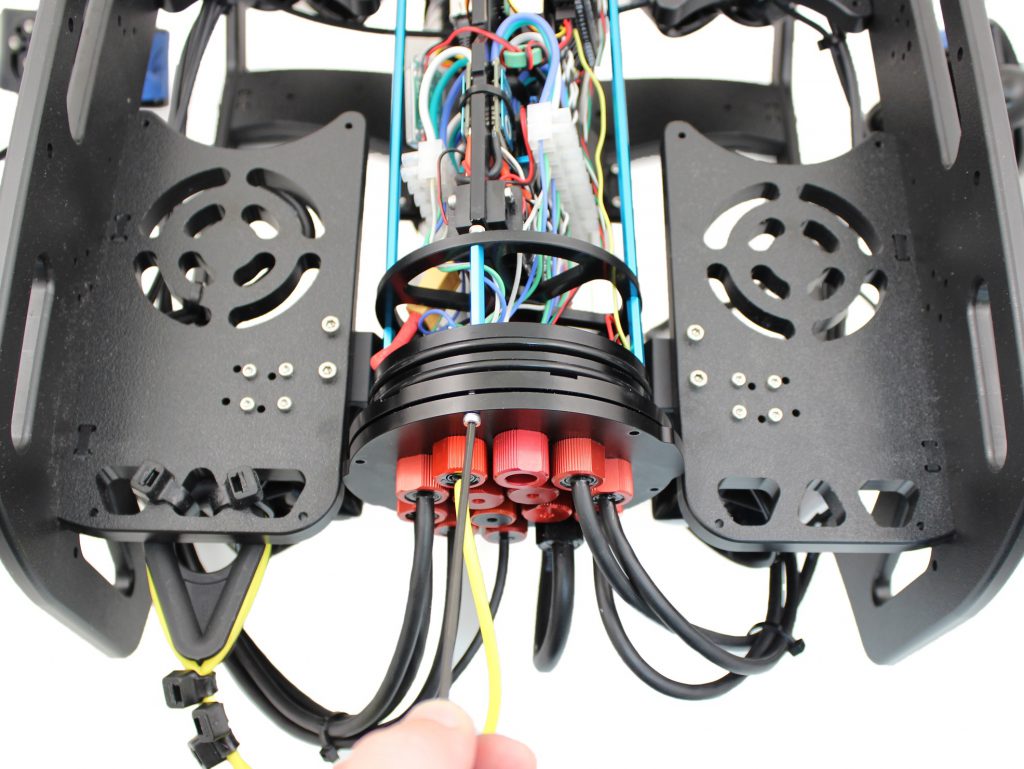
6. Remove the 4” Electronics enclosure from the ROV by removing the M3x16 screws that mount the enclosure to the ROV cradle.
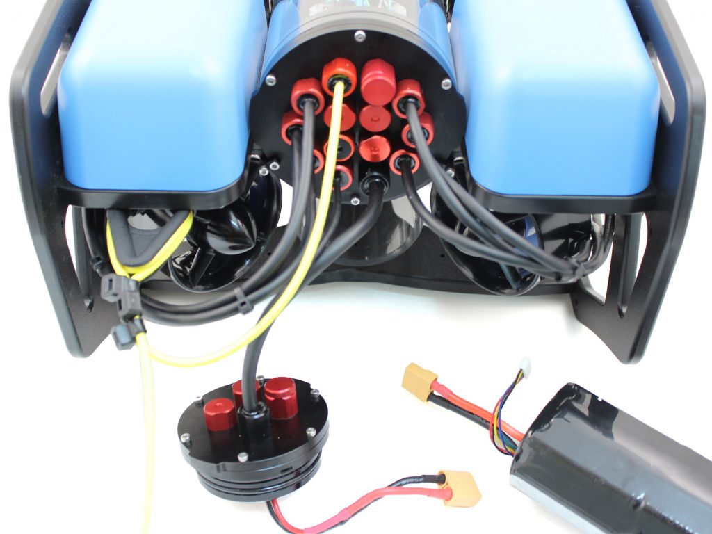
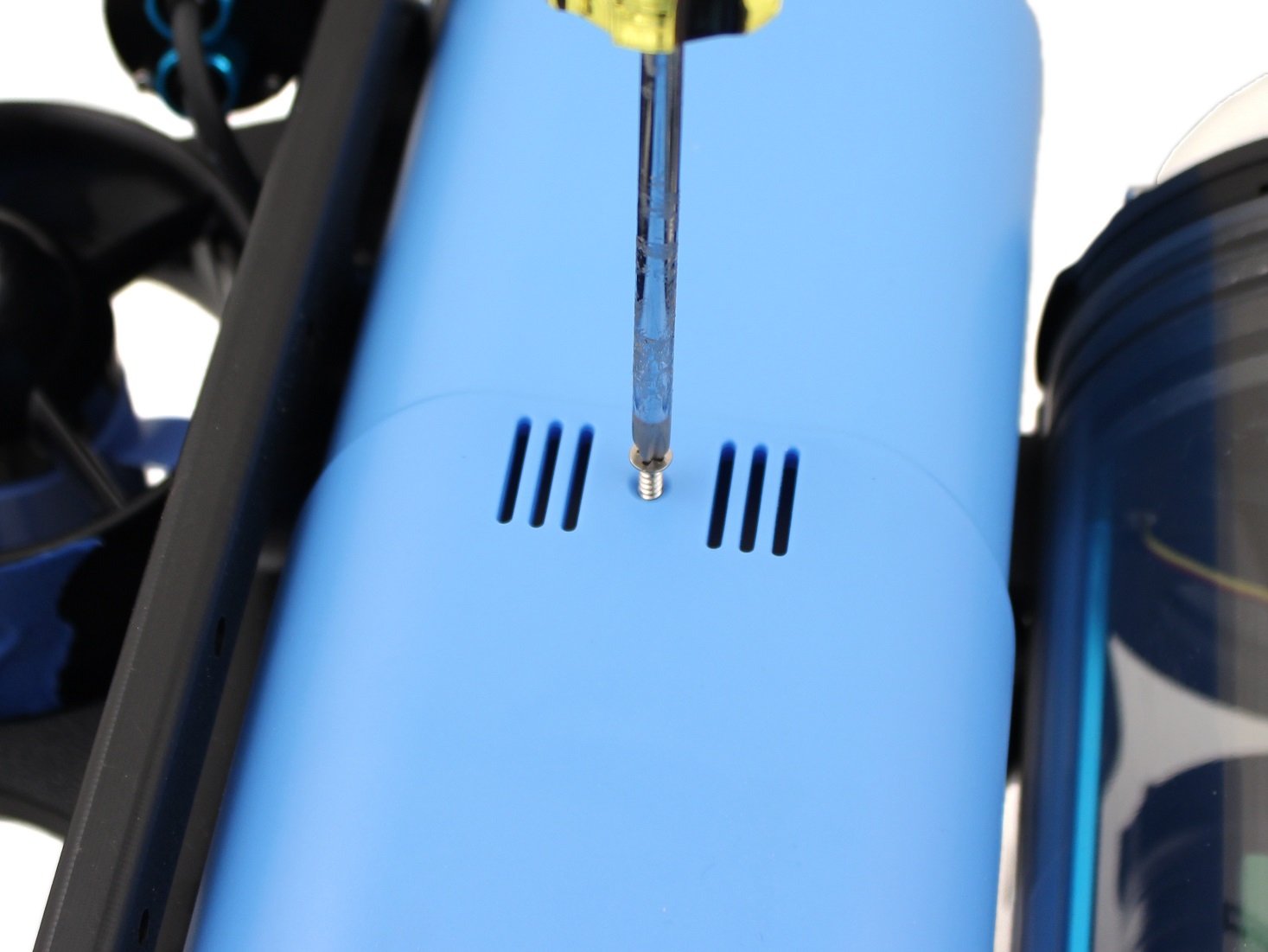
7. Remove the Vent Plug from the Vent Penetrator Bolt on the electronics enclosure.
8. Remove the Aluminum End Cap with 14 Holes by removing the six M3x12 screws using the M2.5 hex driver. Place the M3x12 screws, clips (small L-shaped parts) in a safe place.
9. Remove the two blank penetrators as pictured from the 4” End Cap with the penetrator wrench that came with the BlueROV2 kit.
Install New Thrusters
To Install the new thrusters, you will need the following parts and tools:
- 1 x T200 with counter-clockwise propeller
- 1 x T200 with clockwise propeller
- 2 x Greased O-rings
- 1 x Bag with 8 M3x12 screws
- 8 x M3x12 screws you had set aside from removing Thrusters 5 and 6
- 1 x Silicone Grease – 10g Tube
- 1 x Threadlocker
- 1 x Penetrator wrench
- 1 x 2.5 mm hex driver
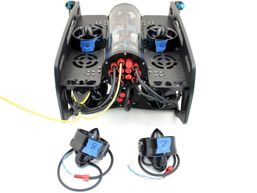
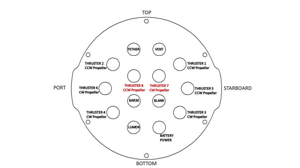
1. Install Thrusters 7 and 8 with greased O-ringss into the respective empty penetrator holes. Tighten to finger tight, then use the provided wrench to tighten them an additional ~1/16 of a turn. If you can’t loosen them with your fingers, they are tight enough.
- Thruster 7 (CW propeller) with red penetrator nut.
- Thruster 8 (CCW propeller) with red penetrator nut.
2. Reinstall the 4” Aluminum End Cap with the following steps:
- Clean the O-ring and make sure that it is free of any debris or damage.
- Clean the O-Ring Flange (4” Series) and make sure that the O-ring groove is free of any debris or damage.
- Apply Silicone grease to the O-ring.
- Install face seal O-ring onto the O-Ring Flange (4” Series).
- Apply one drop of threadlocker to each of the M3x12 screws. Roll the screws around on a paper towel to evenly spread the threadlocker and to remove excess threadlocker.
- Install Aluminum End Cap with 14 Holes with all Cable Penetrators and Blank Penetrators installed onto the O-Ring Flange (4” Series). Do not fully tighten any screws when first installing them; it may cause the O-ring to slip out of its groove. The end cap’s orientation when installed should match the image below. Make sure that the clips are oriented correctly. One should be just right of the Thruster 3 penetrator, and the other should be just left of the Thruster 4 penetrator.
3. Install thrusters 5, 6, 7 and 8, using the M3x12 screws on the outside of the side panels. Tighten the screws so that they indent the frame slightly.
Install New Electronics
To install the new electronics, you will need the following parts and tools:
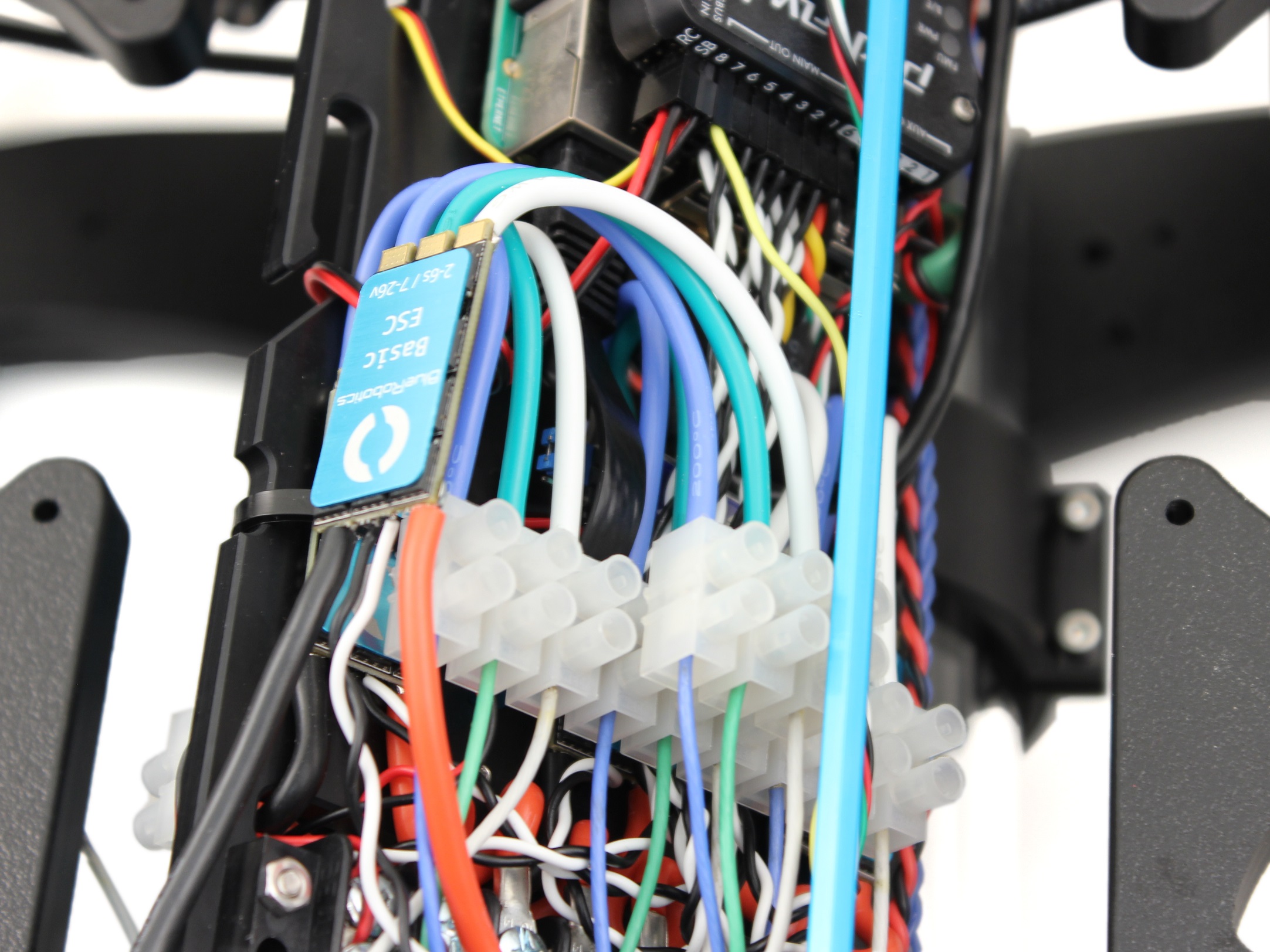
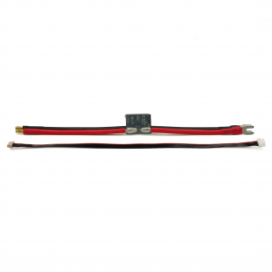
- 2 x Basic ESC
- 2 x 3 Pole Euro Terminal Block
- 1 x Small (~2 mm) flat head screw driver
- 1 x Large (~#2) Phillips head screw driver
1. Slide the new 3 pole Euro terminal blocks into their mounting location on top of the 9 pole Euro terminal blocks. Position it so the aluminum standoff is between 2 of the poles. There is no connection to the existing Euro terminal blocks, they just sit on top.
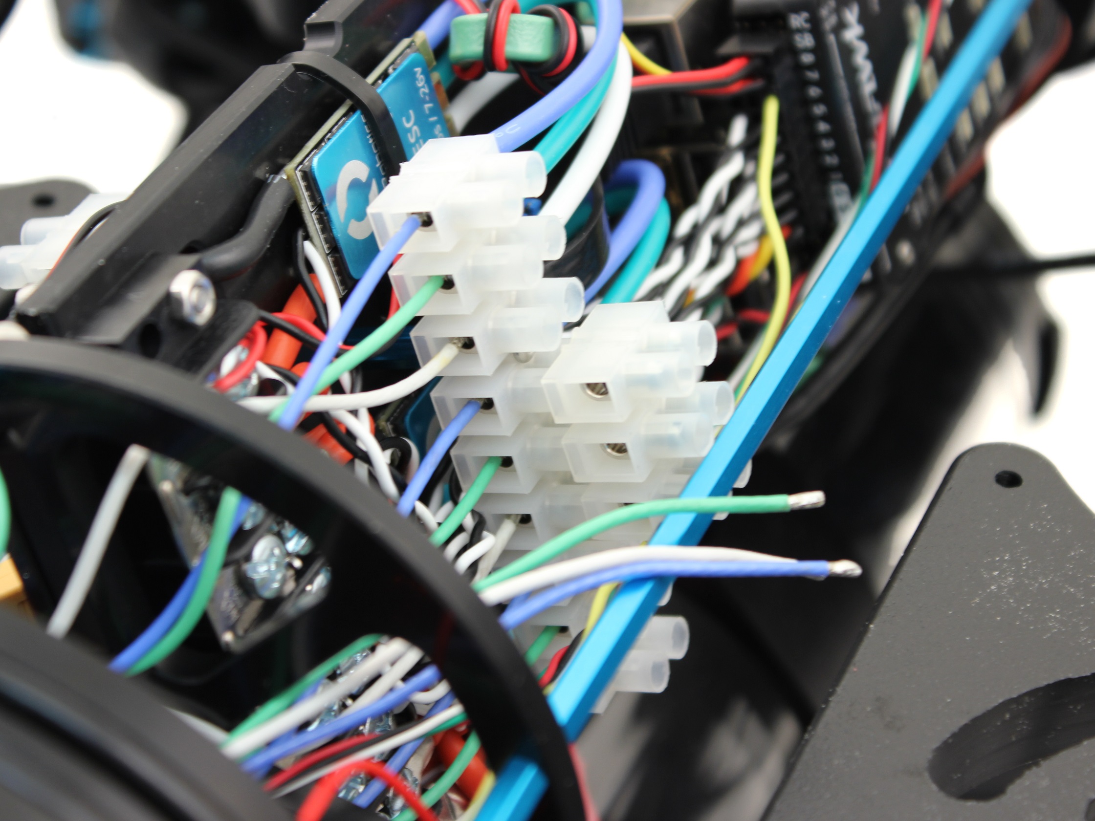
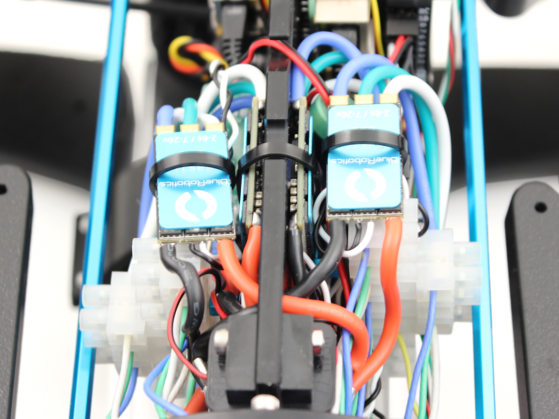
2. Connect the motor power wires from the thrusters 7 and 8 to the 3 pole Euro terminal blocks as shown, using your 2 mm flat head screw driver.
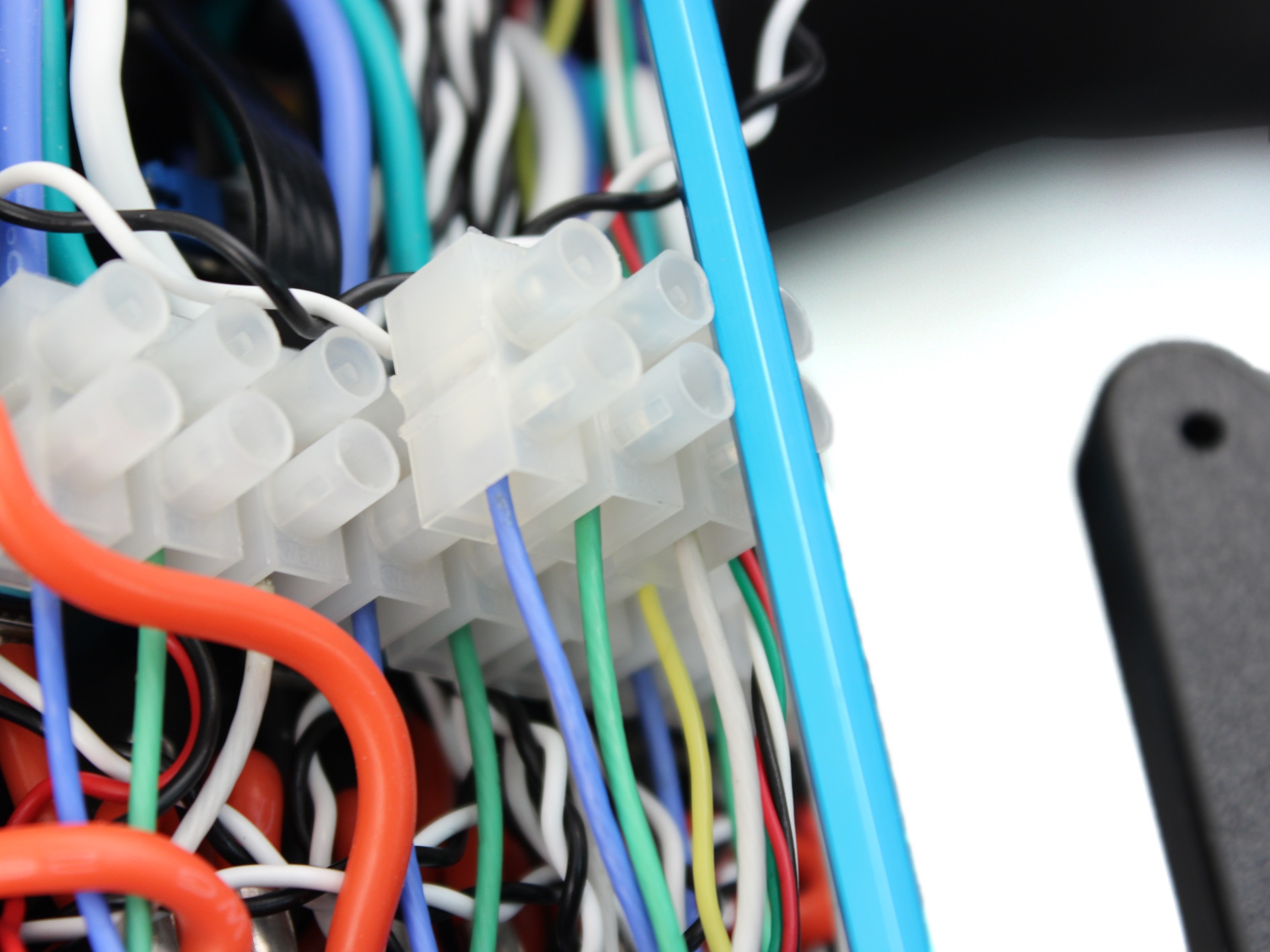
3. Connect the motor power wires from the new ESCs to the 3 pole Euro terminal blocks as shown below, using your 2 mm flat head screw driver.
4. Plug ESC Signal Wires into Pixhawk with the following steps:
- Unplug the Lumen light signal wire from the Pixhawk Channel 7 port and replug it into Aux Channel 1 with the yellow wire oriented toward the bottom of the Pixhawk.
- Unplug the camera tilt servo from Pixhawk Channel 8 and replug it into Aux Channel 2 with the yellow signal wire oriented toward the bottom of the Pixhawk.
- Plug the servo signal wire for Thruster 7 into Channel 7 on the Pixhawk with the white signal wire oriented toward the bottom of the Pixhawk.
- Plug the servo signal wire for Thruster 8 into Channel 8 on the Pixhawk with the white signal wire oriented toward the bottom of the Pixhawk.
5. Connect the ESC Power Wires into open screw terminals on the respective positive and negative terminal blocks.
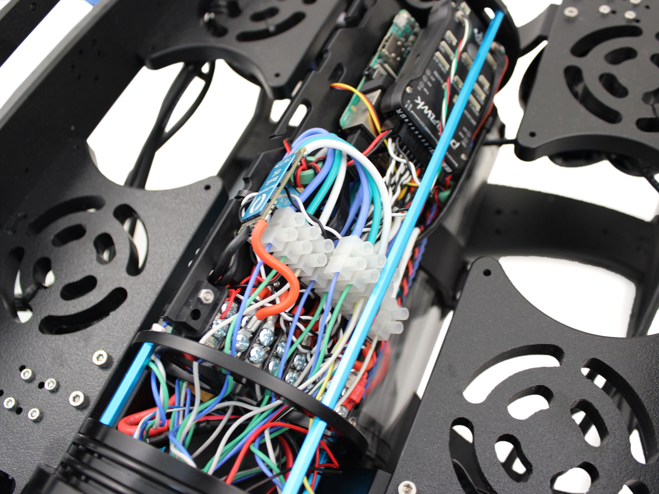
6. Secure the ESCs to the tray using one ziptie each and lightly wrapping them around the other ESC motor power wires.
Install New Thruster Guards
To install the new thruster guards, you will need the following parts and tools:
- 1 Bag of 12 M4x16mm screws
- 1 Bag of #4×0.5” Thread forming screws
- 8 x Heavy Guard Mounting Brackets
- 2 x Heavy Guards
- 1 x Threadlocker
- 1 x #2 Phillips head screwdriver
1. Apply one drop of threadlocker to each of the M4x16mm screws. Roll the screws around on a paper towel to evenly spread the threadlocker and to remove excess threadlocker.
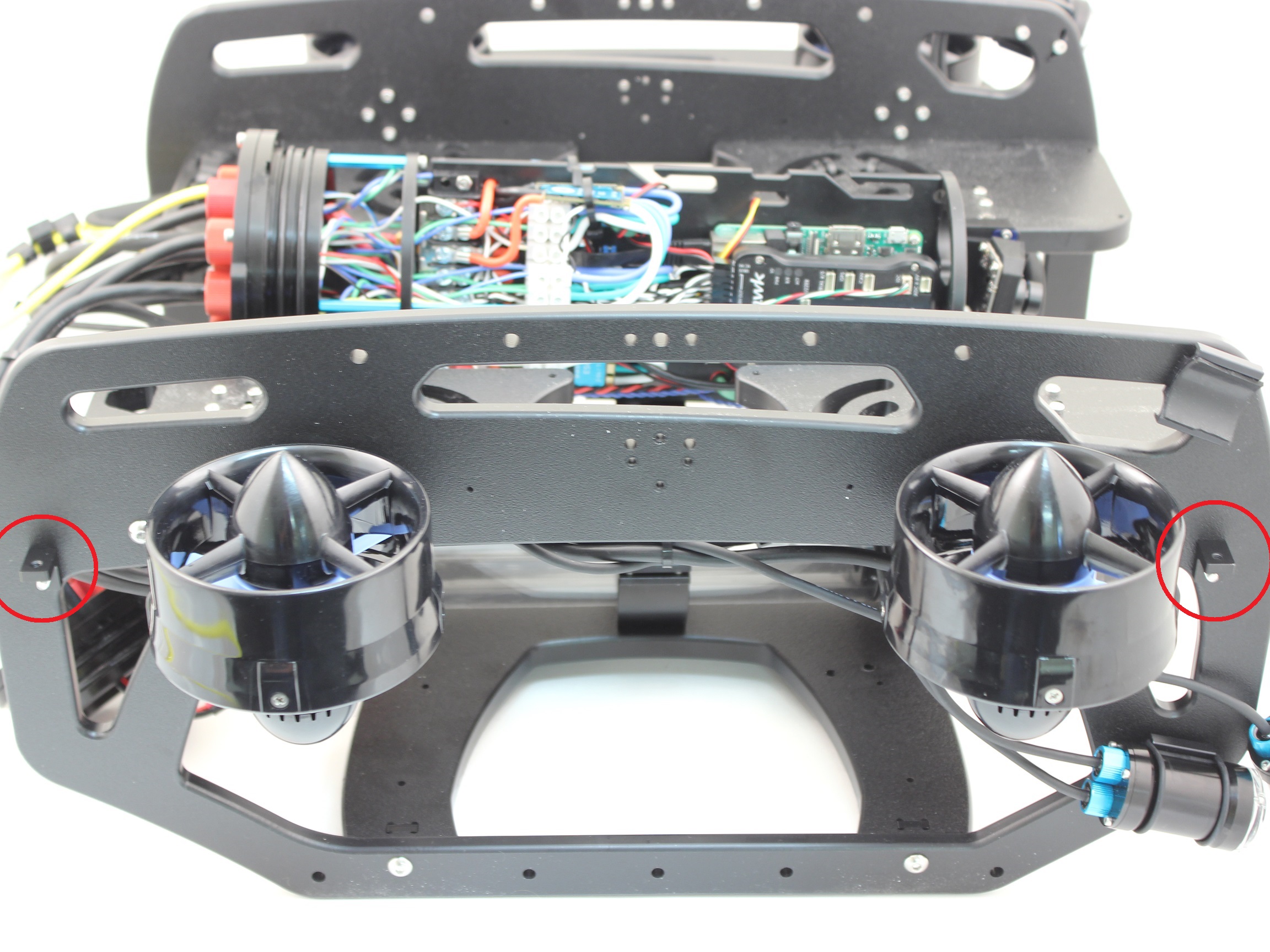
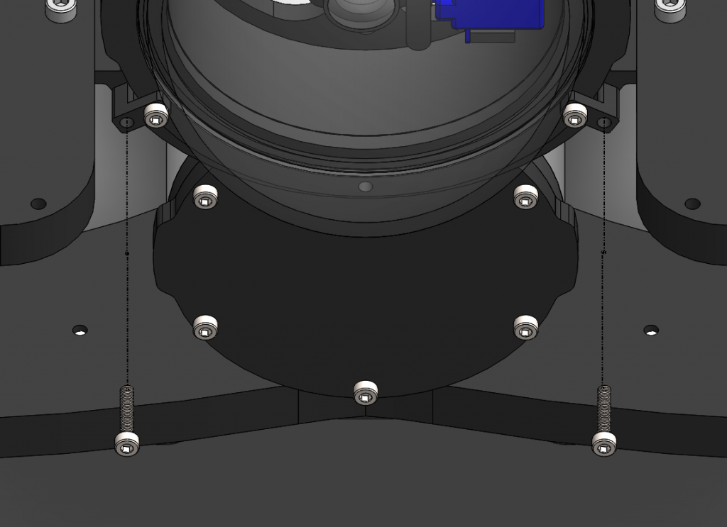
2. Install 4 of the thruster guard mounting brackets on the outside of the frame using 4 M4x16 screws as shown below. The screws should go through the side panels and thread into the brackets on the other side.
3. Place the new thruster guards on the brackets you had previously installed and make sure the holes align. The thruster guards only install in one direction with the shorter leading edge of the guard oriented towards the front end of the vehicle. If you have Lumen lights mounted in the top mounts, make sure to arrange the wire so it is inside the guard, near the thruster duct. Secure the guards to the brackets using 4 M4x16 screws.
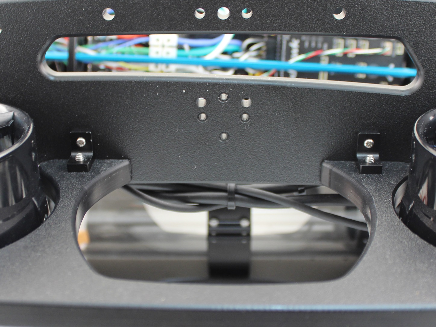
4. Install four more thruster guard mounting brackets (two on each side) in the holes near the middle of the ROV using one M4x16 screw and one #4×0.5” thread forming screw per bracket.
5. Tighten all the screws evenly until they are tight enough to properly secure the thruster guard to the frame and there is no excess freedom of movement.
Reassemble BlueROV2 Electronics Enclosure
To reassemble your BlueROV2 electronics Enclosure, you will need the following parts and tools:
- 4 x M3x16 screws that were placed off to the side during disassembly
- 1 x Silicone Grease – 10g Tube
- 1 x 2.5 mm hex driver
Reinstall 4” Watertight Enclosure onto ROV with the following steps:
1. Apply silicone grease to the two radial O-rings on the O-Ring Flange (4” Series) that is attached to the Electronics Tray then install the Watertight Enclosure (4” Series) with installed Dome End Cap to the O-Ring Flange (4” Series).
2. Mount the Electronics Enclosure to the frame using the M3x16 screws so that the dome is on the same side as the front center panels (the center panels without the 3 large holes). Install the M3x16 screws through the clips and into the Enclosure Cradle (4” Series). It is easier to install these screws if the clips are not fully tightened until all screws are through the clips and threading into the Enclosure Cradle (4” Series). This allows to clips to rotate so you can find the threaded hole in the Enclosure Cradle (4” Series) easily.
Cable Management
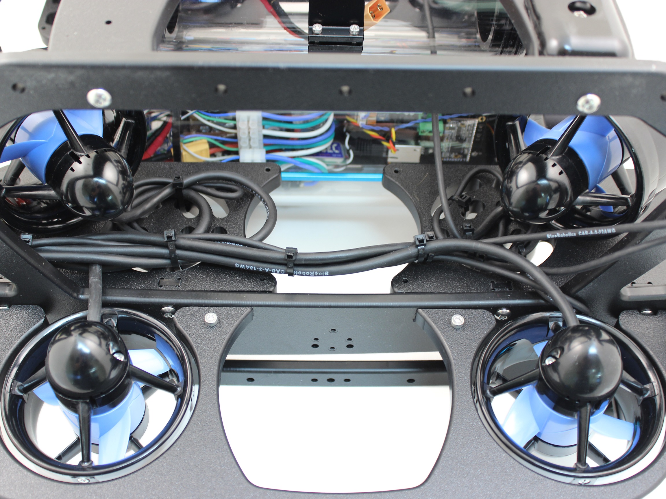
To clean up the thruster and lumen wires, you will need the bag of 30 zip ties and your scissors/wire cutters.
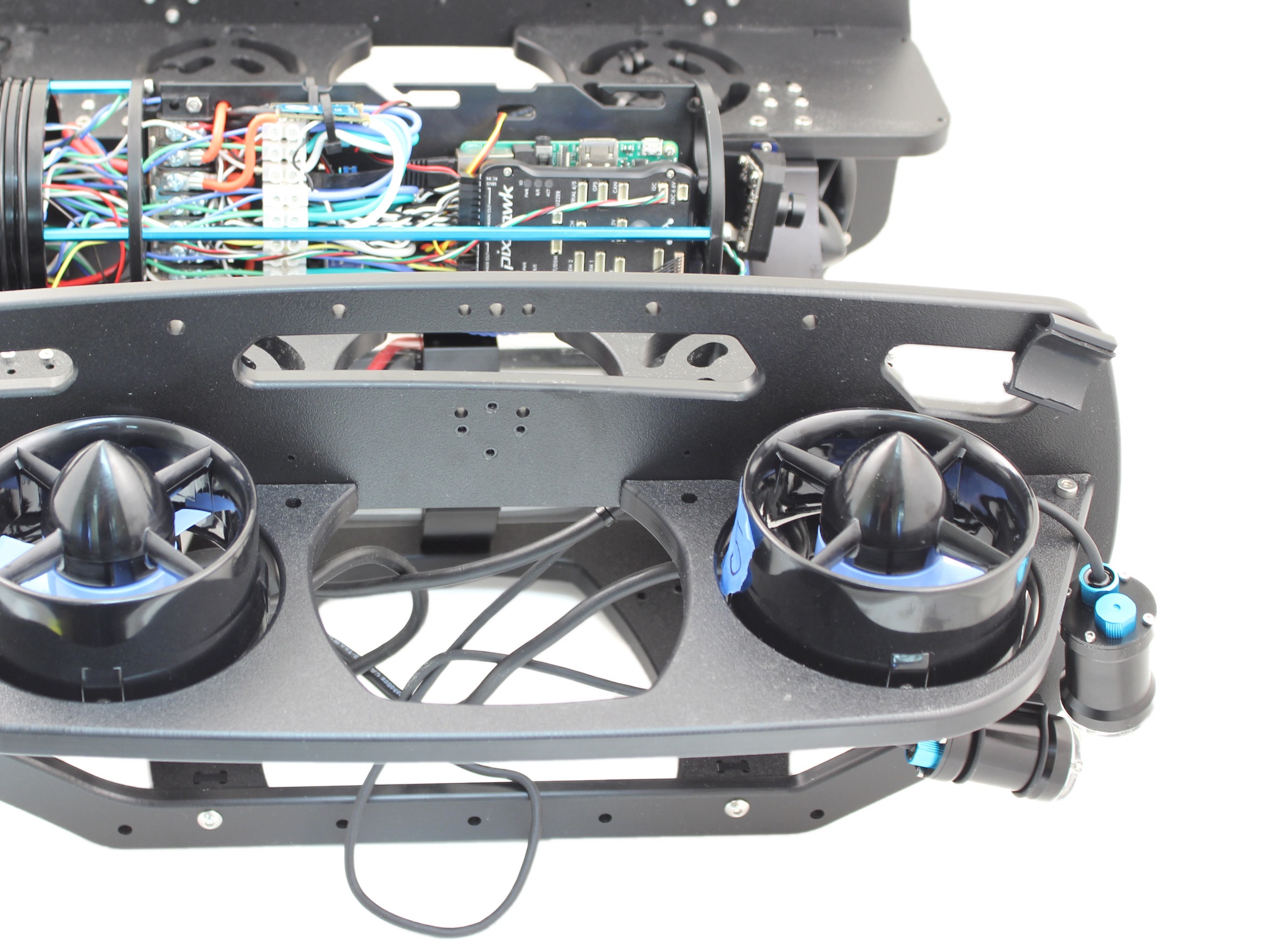
The primary goal of Thruster and Lumen cable management is to prevent the wires from getting cut by the propellers. Make sure to check that no wire can reach a propeller after you have finished routing the cables. Below are some examples of what the cable routing should look like.
Install New Buoyancy Blocks and Fairings
To install the new buoyancy blocks and fairings, you will need the following parts and tools:
- 16 x Fairing screws that were placed off to the side during disassembly
- 4 x Fairings with buoyancy installed that were placed off to the side during disassembly
- 2 x Heavy additional buoyancy blocks
- 2 x Heavy fairings
- 1 x Bag of 4 fairing screws
- 1 x #2 Phillips head screwdriver
1. Reinstall Original Fairing Blocks onto ROV by installing the screws through the center panels and into the fairings.
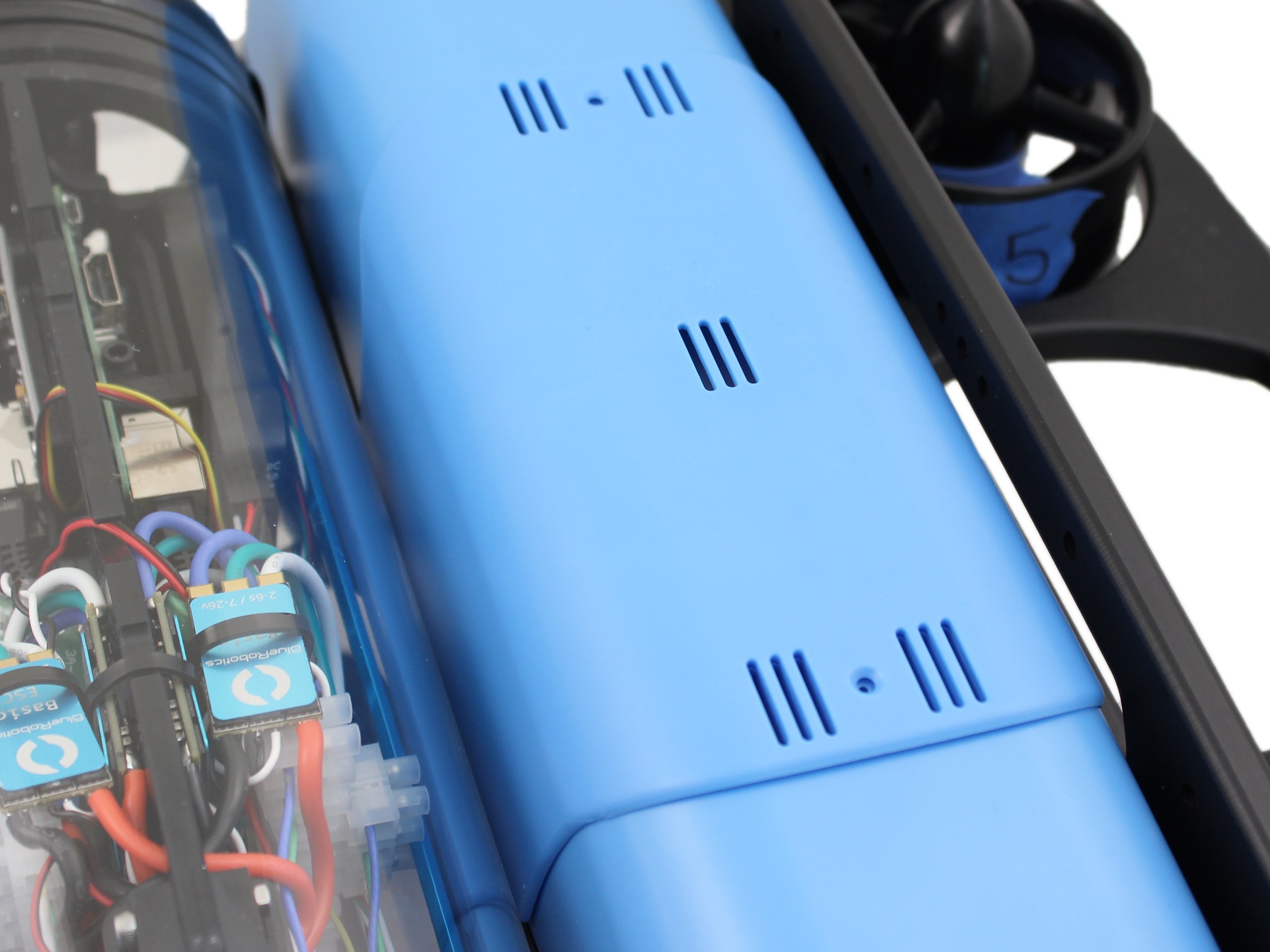
2. Place the new round Heavy buoyancy blocks into the open space where Thrusters 5 and 6 used to be. Ensure the flat sides of the blocks are parallel to the sides of the ROV.
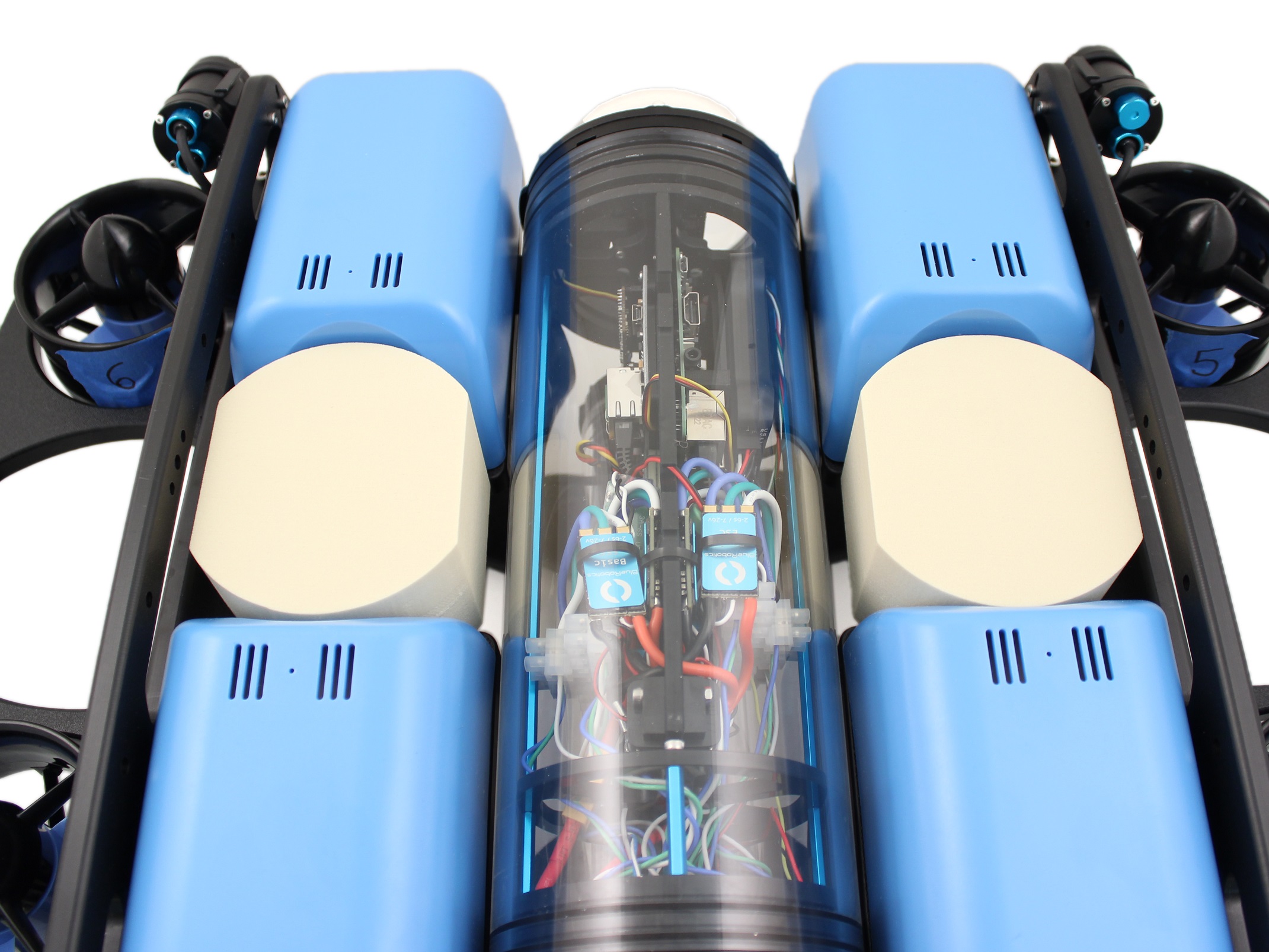
3. Place the new plastic Heavy fairings on top of the buoyancy blocks and secure them to the old fairing blocks using the included self-tapping fairing screws.
Mounting Additional Ballast to the Frame
To mount the ballast to the frame you need the following parts and tools:
- 7 x 200g ballast weights (from original BlueROV2 Kit)
- 3 x 200g ballast weights (from Heavy Retrofit Kit)
- 10 x 8-16 Thread, 5/8” Long, Thread-Forming Screws
- 1 x #2 Phillips head screwdriver
To get the longest battery life and the best driving experience, it is important to have the ROV close to balanced from front to back in water and close to neutrally buoyant. The Heavy Retrofit kit adds a bit of weight and more buoyancy to the ROV, so it will need to be re-trimmed based on your operating conditions. Trimming the ballast may involve a bit of trial and error.
Software Setup
Finally, before operating your ROV, we need to update the software configuration. Begin by powering on your ROV, connecting it to your computer, and opening QGroundControl.
Load New Parameters
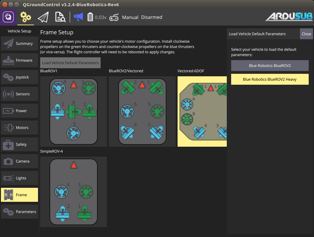
1. Go to the Frame tab of the Vehicle Setup page (click the gears icon)
2. Click ‘Load Vehicle Defaults’
3. Click BlueROV2 Heavy. A green bar will move across the top of the screen indicating the progress of loading the parameters; this is usually pretty quick.
4. Reboot the vehicle
5. Follow the respective guide for re-entering the parameter values for the Power Module (depreciated) or Power Sense Module (current).
Power Sense Module (PSM) Installation
Configure Motor Directions
The motor directions for the BlueROV2 must be configured prior to operation.
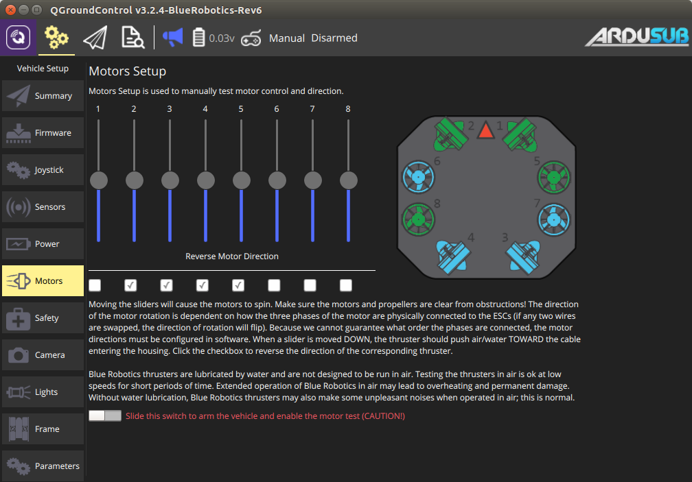
1. Go to the *Vehicle Settings* page in QGroundControl and select the Motors tab in the sidebar on the left.
2. Read and understand the instructions on the setup page.
3. Arm the BlueROV2 by clicking the switch on the page.
4. One at a time, move each slider, and make sure that the motor that spins is pushing air in the correct direction. If a motor is spinning in the wrong direction, click the corresponding checkbox under the ‘Reverse Motor Direction’ section to correct the motor rotation.
5. When you are finished with the setup, disarm the ROV by clicking the switch.
Roll and Pitch Input
Please refer to the “Controller Functions” section of the BlueROV2 Operating Guide for roll and pitch input options.
Issue Reporting
We’re always trying to make our documentation, instructions, software, and user experience better. If you’re having an issue with anything, please report it so that we can address it as soon as possible! Here’s where to do that depending on what’s wrong:
- ArduSub Issues: For anything related to the ArduSub software that runs on the Pixhawk and controls the ROV, reports issues on the ArduSub Github Issues Page. If you’re unsure where your issue should be posted, you can report it here.
- QGroundControl Issues: For anything related to the QGroundControl software, joystick setup, video streaming, etc., please report an issue on the QGroundControl Github Issues Page.
- Documentation: For anything related to the documentation and instructions here, please report an issue by submitting an e-mail to [email protected].