
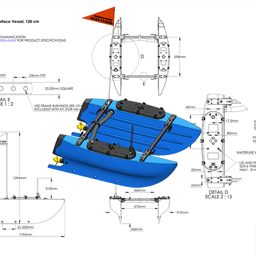
BlueBoat Assembly Guide
The BlueBoat is the planet’s most affordable robotic surface vessel. This guide will show you how to assemble the BlueBoat kit.
The BlueBoat base kit includes all of the tools you’ll need to assemble your BlueBoat. Assembly takes around one to two hours. Ensure you have plenty of space and a well-lit work area.
If you purchased any accessories with your BlueBoat, open their installation guide and follow along while assembling your BlueBoat. Some popular guides are linked below.
Installing the BlueBoat Antenna and Accessory Mast
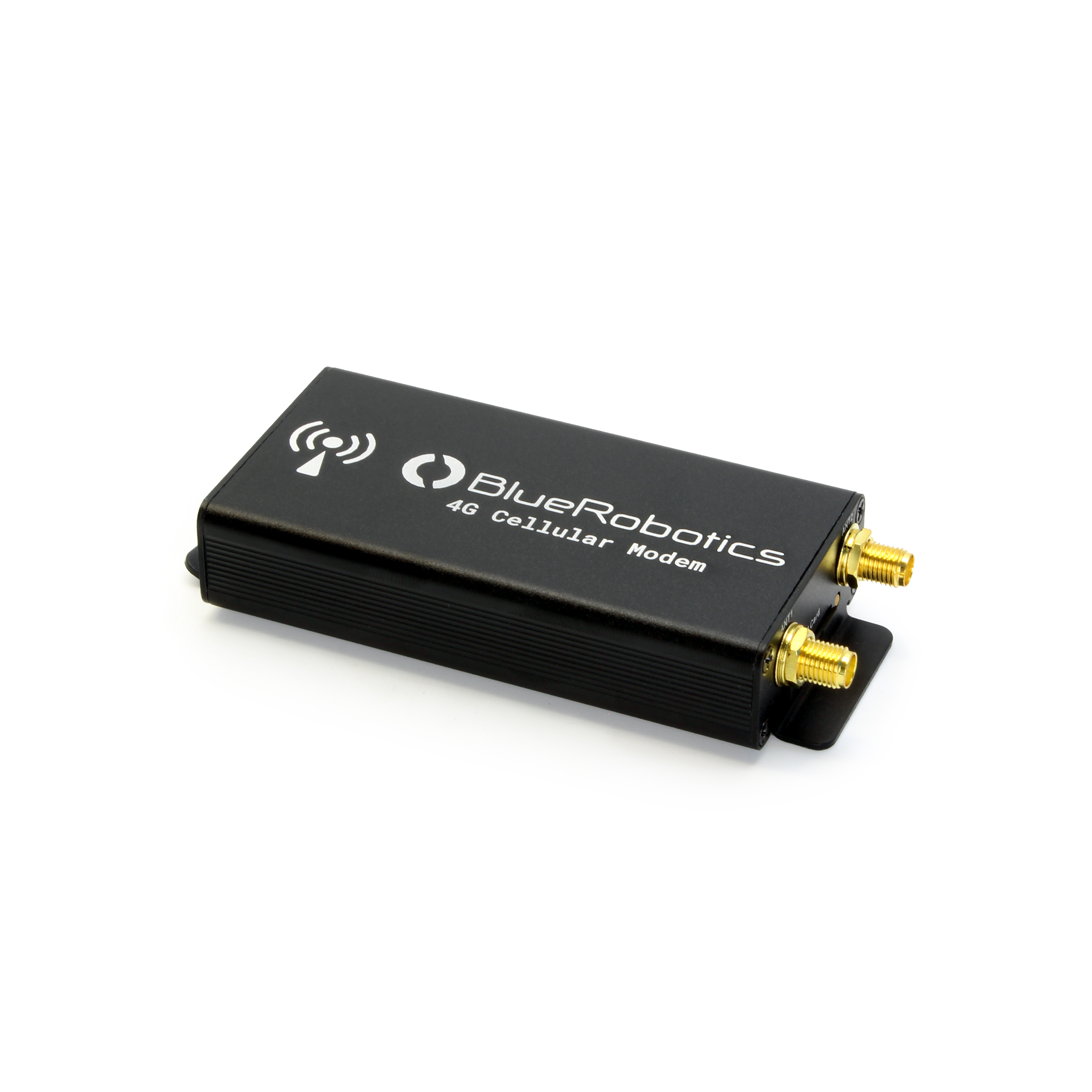
Installing the BlueBoat Cellular Modem
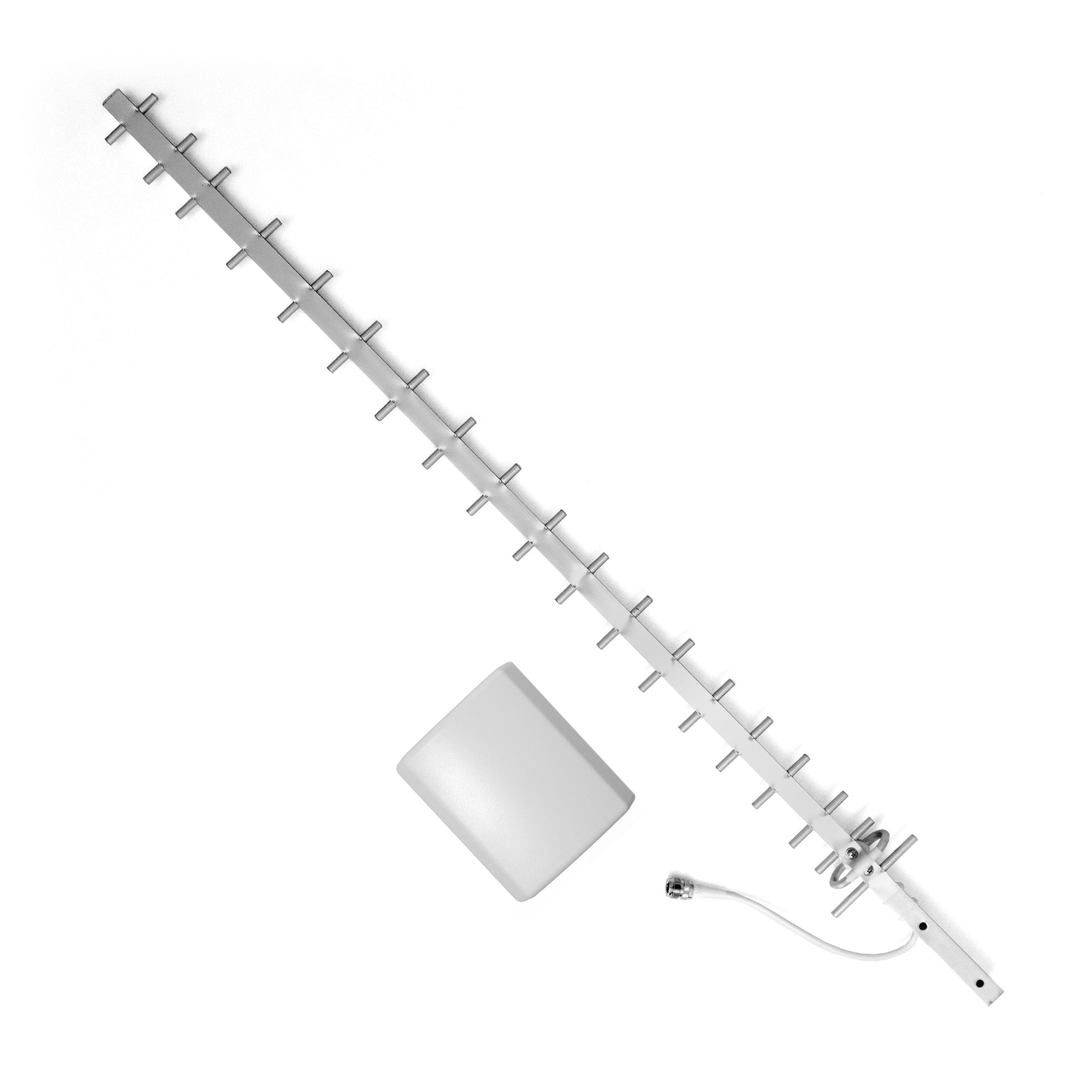
BaseStation Directional Antenna Kit Guide
Ping Integration Kit for BlueBoat Installation Guide
Integrating the Omniscan 450 SS on the BlueBoat
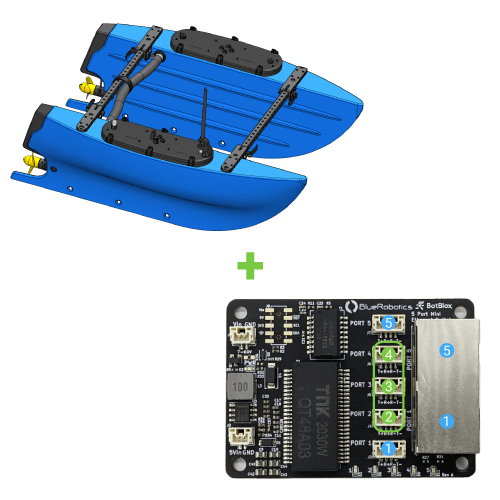
Ethernet Switch Installation Guide for the BlueBoat
Some tips before you start:
- If you need help with any part of the assembly, please reach out to us here.
- Screw sizes are given in metric and follow the format M#x#. The first number (M#) represents the screw’s diameter—a larger number indicates a thicker screw. The second number represents the length—a larger number means a longer screw.
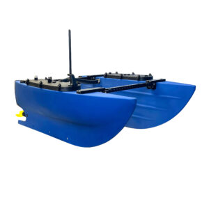
- 2 x BlueBoat hull (starboard and port) and 1 x towel
- 2 x Hatch lid assembly (starboard and port)
- 2 x Frame assembly
- 1 x Crosstube assembly (with cables)
- 2 x 4S splitter cable
- 1 x Charge cable
- 1 x Antenna assembly
- 1 x Flag
- Crosstube hardware
- 2 x Crosstube C-nut
- 2 x -129 O-ring
- 1 x Hook and loop strap with buckle
- 1 x Molykote 111 silicone grease 6g
- Propeller set
- 2 x Weedless propeller (LH and RH)
- 4 x M3x8 Socket head cap screw
- BlueBoat tools
- 2 x BlueBoat Wrench
- 1 x 2.5 mm hex driver
- 1 x 4 mm hex key
- 1 x 5 mm hex key
- Antenna Guard
- 1 x Hatch Lid Antenna Guard
- 2 x M6x14 flanged button head screws
- Frame hardware
- 4 x M6x14 flanged button head screws
- 8 x M6x20 flanged button head screws
- Flagpole mount
- 1 x Flagpole mount
- 1 x M5x5 cup-point set screw
- 12 x Frame bushing spares
- Fixed frame hardware
- 4 x M6x55 socket head cap screw (bolt)
- 4 x M6 lock nut
- 8 x M6 18 mm washer
- 1 x USB Ethernet adapter and 4 x cable ties
- Battery Velcro strip set
- 8 x Velcro strip
- 2 x 70% Alcohol wipe
- Sticker set
- Fuse spares
- 1 x 150A MIDI fuse
- 2 x 50A MIDI fuse
- 5 x 2A MINI blade fuse
- 5 x 5A MINI blade fuse
- 5 x 10A MINI blade fuse
- Spare hardware set
- 2 x M6x20 flanged button head screws
- 2 x M6x14 flanged button head screws
- 2 x M4x10 flanged button head screws
- 2 x M3x8 socket head cap screw
- 2 x M5x5 cup-point set screw
- 1 x Frame clamp thumb nut
- 2 x BlueBoat hull (starboard and port)
- 2 x Frame assembly
- 1 x Bag of Frame Hardware
- 4 x M6x14 flanged button head screws
- 8 x M6x20 flanged button head screws
- 1 x 4 mm hex key
- 1 x Crosstube assembly (with cables)
- 2 x BlueBoat Wrench
- 1 x Bag of crosstube hardware
- 2 x Crosstube C-nut
- 2 x -129 O-ring
- 1 x Hook and loop strap with buckle
- 1 x Molykote 111 silicone grease 6g
- 1 x Propeller set
- 2 x Weedless propeller (LH and RH)
- 4 x M3x8 Socket head cap screw
- 1 x 2.5 mm hex driver
- 2 x Hatch lid assembly (starboard and port)
- 2 x 4S splitter cable
- 2 x Cable ties
- the starboard power cable
- the port power cable
- the port motor PWM cable
- the starboard motor cable to the motor cable from the rear of the hull
- the port power cable
- the port motor PWM cable
- the port motor cable to the motor cable from the rear of the hull
- 1 x Antenna assembly
- 1 x Bag with Antenna Guard
- 1 x Hatch Lid Antenna Guard
- 2 x M6x14 flanged button head screws
- 1 x Bag with flagpole mount
- 1 x Flagpole mount
- 1 x M5x5 cup-point set screw
- 1 x Flag
- 1 x 2.5 mm hex driver
- 1 x 4 mm hex key
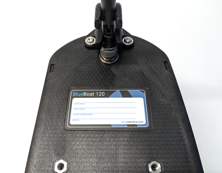
- 1 x BlueBoat identification sticker
- 1 x On/off switch sticker
- 2 x Caution sticker
- 4 x Alcohol wipe
- 4 x Frame bushing (from bag of spares)
- 1 x Bag of fixed frame hardware
- 4 x M6x55 socket head cap screw (bolt)
- 4 x M6 lock nut
- 8 x M6 18 mm washer
- 1 x BlueBoat Wrench
- 1 x 5 mm hex key
- 1 x 2.5 hex driver
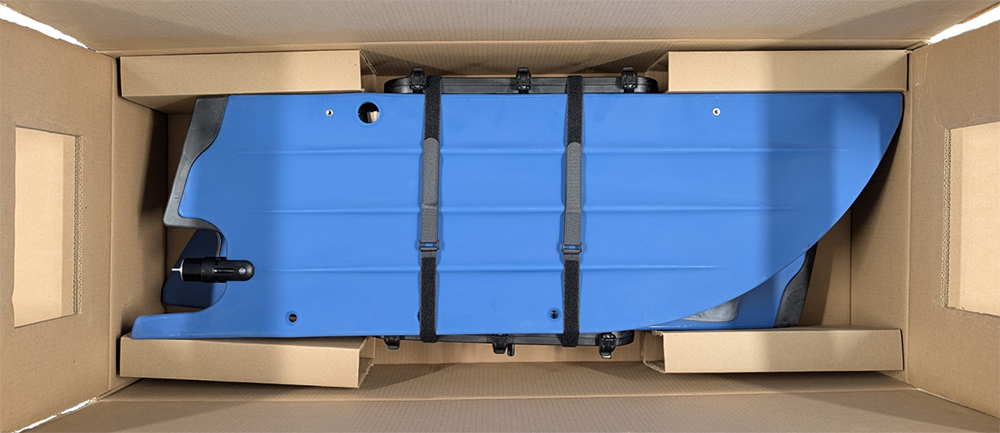
Unpacking the BlueBoat Kit
1. Unfasten and remove the Velcro straps to separate the BlueBoat hulls.
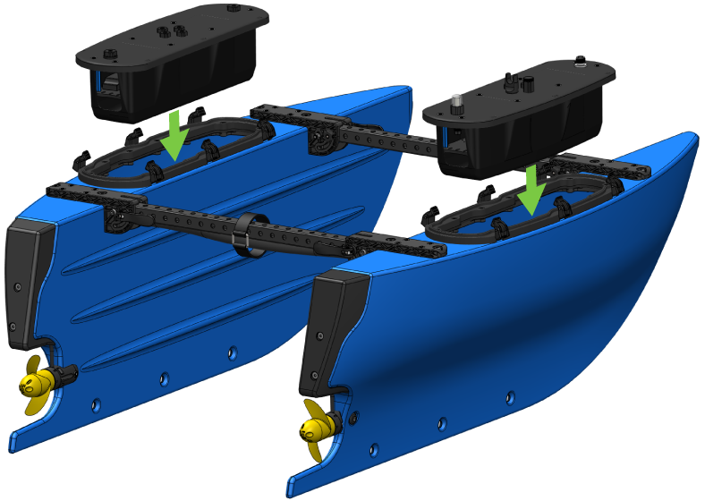
2. To open the hatch lids, press in the lower latch clips to release them, then push the top of the latch outward, away from the lid. Remove the hatch lid assembly from each hull and set them to the side.
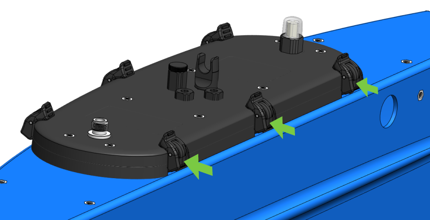
Releasing the latches.
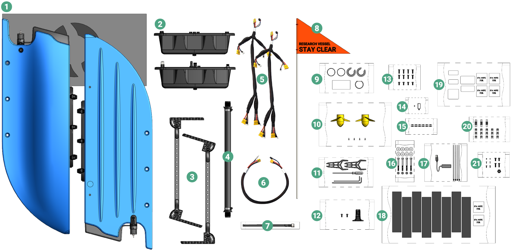
3. Unpack the contents of each hull. After unpacking the BlueBoat box and hulls, you should have the following components:
Connecting the Hulls
To connect the BlueBoat hulls you will need:
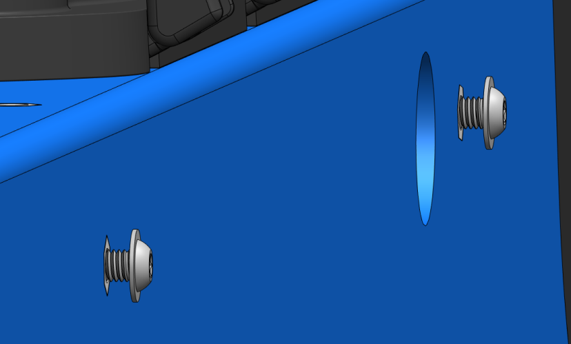
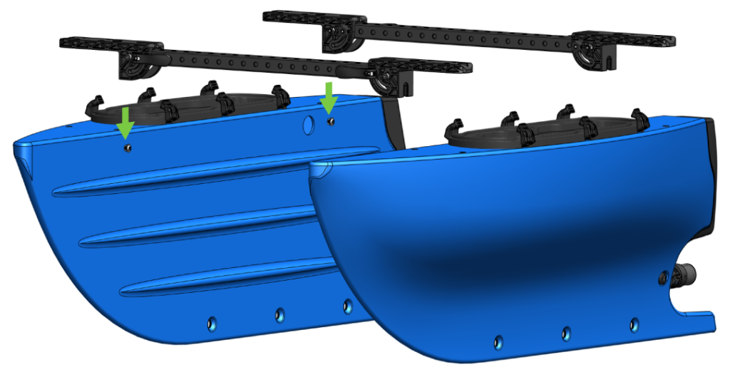
1. Inside the bag of frame hardware, you will find four M6x14 flanged button head screws and eight M6x20 flanged button head screws. Take the four shorter M6x14 screws and partially thread them into the threaded inserts located on the flat side of the hulls.
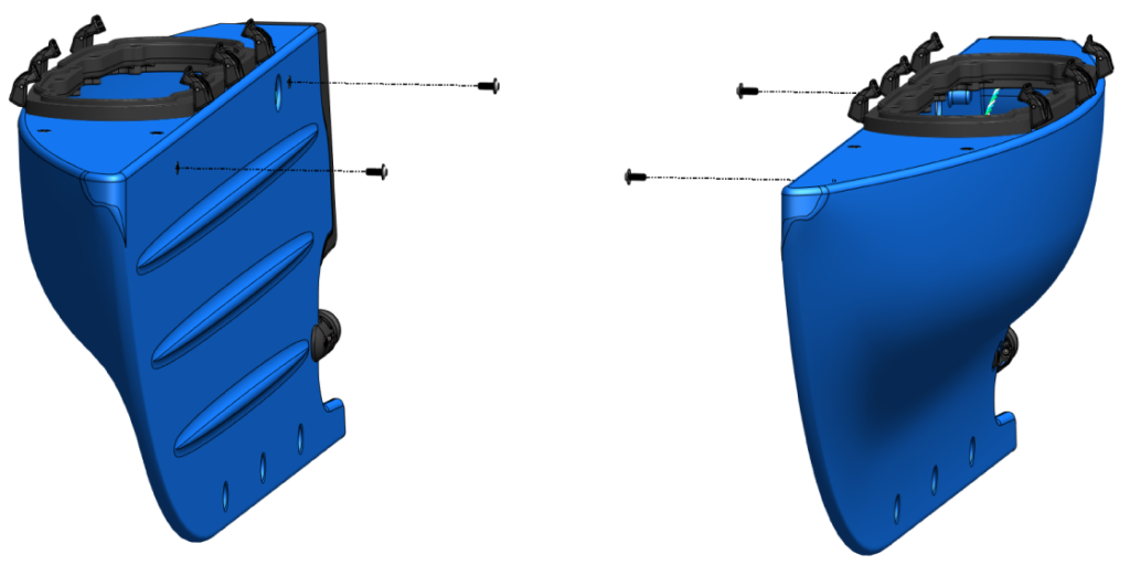
Leave about a 6 mm (~¼ inch) gap between the screw head and the hull.
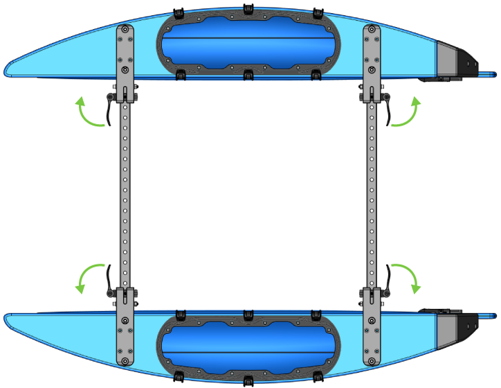
2. Release the clamp handles on both frame assemblies and unfold them so they are fully extended. Close the clamp handles to lock the frame assemblies in the fully extended position.
3. Install the frame assemblies by sliding the frame assembly brackets over the M6x14 screws so the screw is captured by the slot in the bracket. Back the screw out a little bit more if it is difficult to slide into the slot.
The frame assemblies should be oriented so the clamp handles open outward, away from the center of the boat. Do not tighten the screws yet.
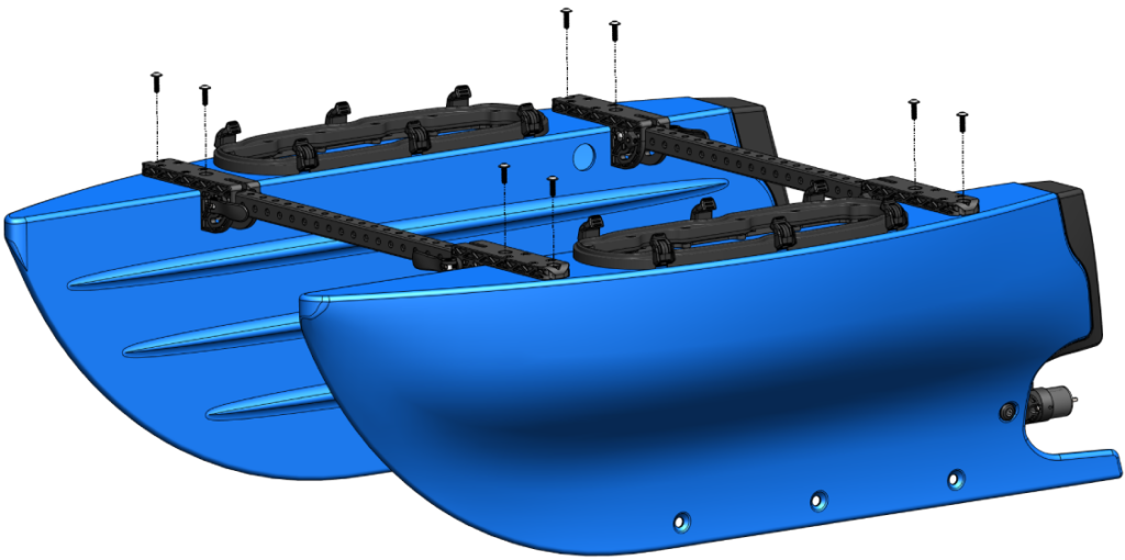
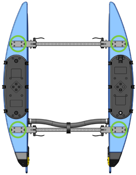
4. Secure the frame assemblies to the hulls using the remaining eight M6x20 screws, do not fully tighten the screws until all the screws are in place. Once all the screws are in place, use the 4 mm hex key to fully tighten all twelve M6 screws. Do not forget about the first four M6x14 screws under the frame brackets! Tighten the screws to about ¼ to ½ turn past snug.
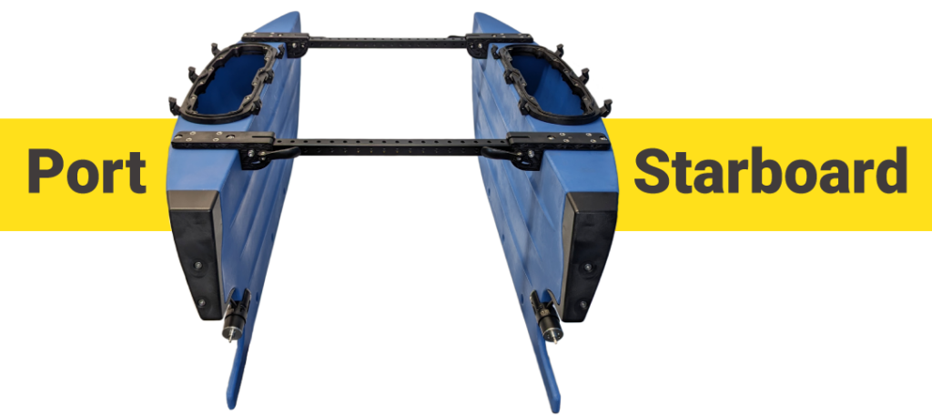
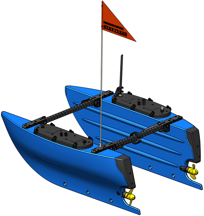
5. Your BlueBoat should now look like this. Going forward, we will refer to the left side and right sides of the boat using the nautical terms “port” and “starboard”. If you imagine you are a tiny passenger on the BlueBoat, facing the front of the boat, the left side is the port side and the right is the starboard side.
Installing the Crosstube
To install the crosstube you will need:
1. Remove the two O-rings from the bag and apply a thin, even coat of the included Molykote 111 silicone grease to them. Install one O-ring on each end of the crosstube assembly. The O-rings should sit in the groove in the crosstube barb.
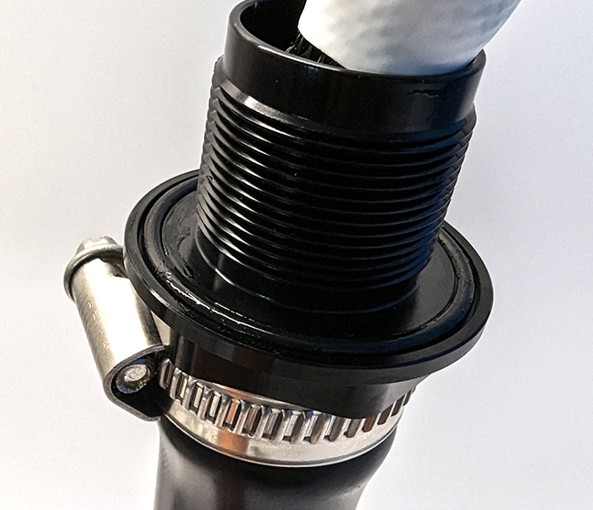
O-ring installed in barb.
2. Each end of the cross cable assembly inside the crosstube is labeled to indicate which hull it should be connected to.
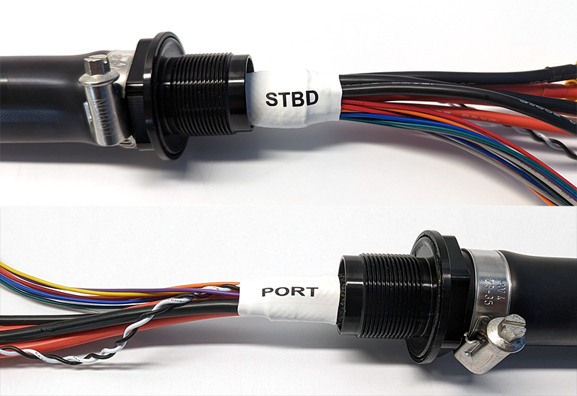
Connect the end labeled “STBD” to the starboard hull and the end labeled “PORT” to the port hull. Fully insert the cables and threaded barb ends into the holes near the rear crossbar of each hull.
3. Thread the crosstube C-nuts onto the barbs inside the hulls. Use one of the included wrenches to hold the barb in place while you use the other wrench to fully tighten the C-nut inside the hull.
Use the wrench to hold the barb.
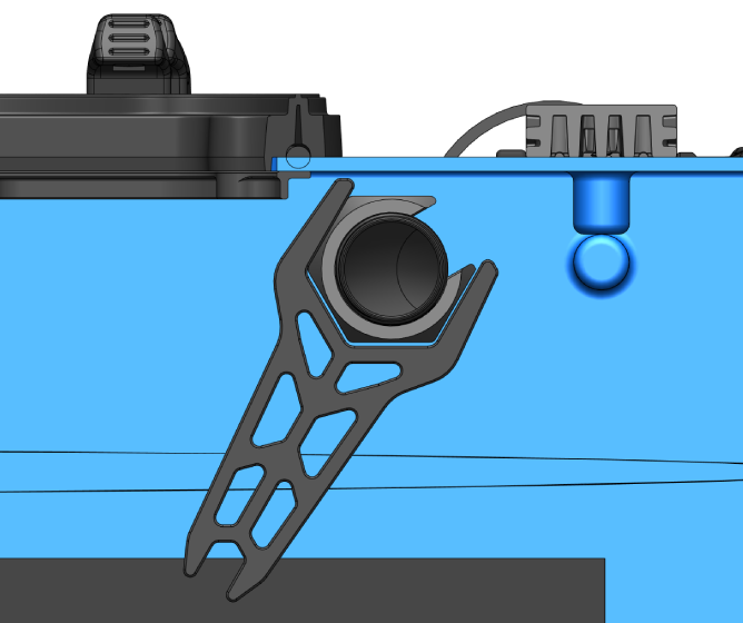
Tighten the nut inside the hull.
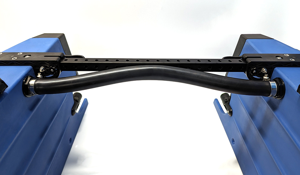
4. Use the included strap to secure the crosstube to the rear crossbar.

Installing the Propellers
To install the propellers you will need:
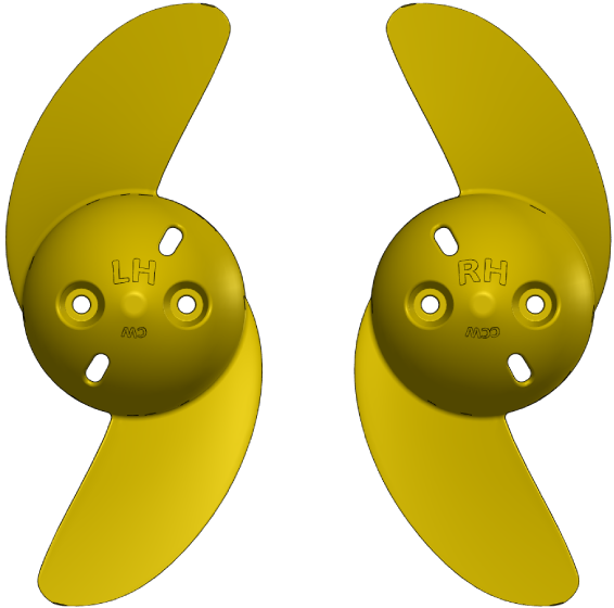
1. The propellers are marked with “LH” for the Left-Hand propeller and “RH” for the Right-Hand propeller.
2. Use the 2.5 mm hex driver and M3x8 socket head cap screws to install the propellers on the M200 motors. Install the LH propeller on the M200 motor on the port side and the RH propeller on the M200 motor on the starboard side. Make sure you are screwing into the threaded screw holes and not the unthreaded rotor ventilation holes.
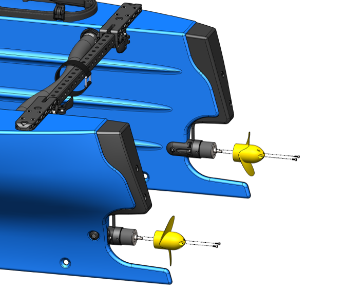
Installing propellers.
Installing the Hatch Lid Assemblies and Splitter Cables
For this section you will need:
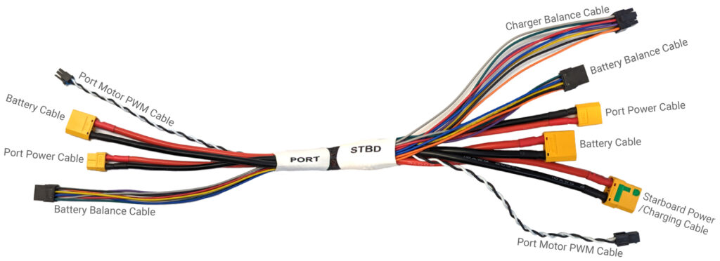
The diagrams below identify all the cables within the cross cable and the hatch lid assemblies for reference. The number of cables and connectors may seem intimidating at first, but every cable connector is keyed and only mates with one other connector, so you should not worry about connecting anything the wrong way.
Cross Cable
| Cable | Connector |
|---|---|
| Starboard | |
| Starboard Power/Charging Cable | XT90S female |
| Port Power Cable | XT60 male |
| Battery Cable | XT90 male |
| Battery Balance Cable | 8-pin Molex Micro-Fit male |
| Charger Balance Cable | 8-pin Molex Micro-Fit female |
| Port Motor PWM Cable | 2-pin Molex Micro-Fit male |
| Port | |
| Port Power Cable | XT60 female |
| Battery Cable | XT90 male |
| Battery Balance Cable | 8-pin Molex Micro-Fit male |
| Port Motor PWM Cable | 2-pin Molex Micro-Fit female |
Hatch Lid Assembly Cables
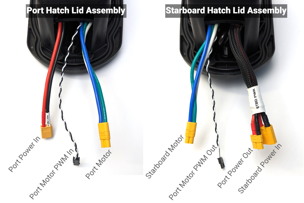
| Cable | Connector |
|---|---|
| Starboard | |
| Starboard Power In | XT90 male |
| Port Power Out | XT60 female |
| Port Motor PWM Out | 2-pin Molex Micro-Fit female |
| Starboard Motor | MT60 female |
| Port | |
| Port Power In | XT60 male |
| Port Motor PWM In | 2-pin Molex Micro-Fit male |
| Port Motor | XT60 female |
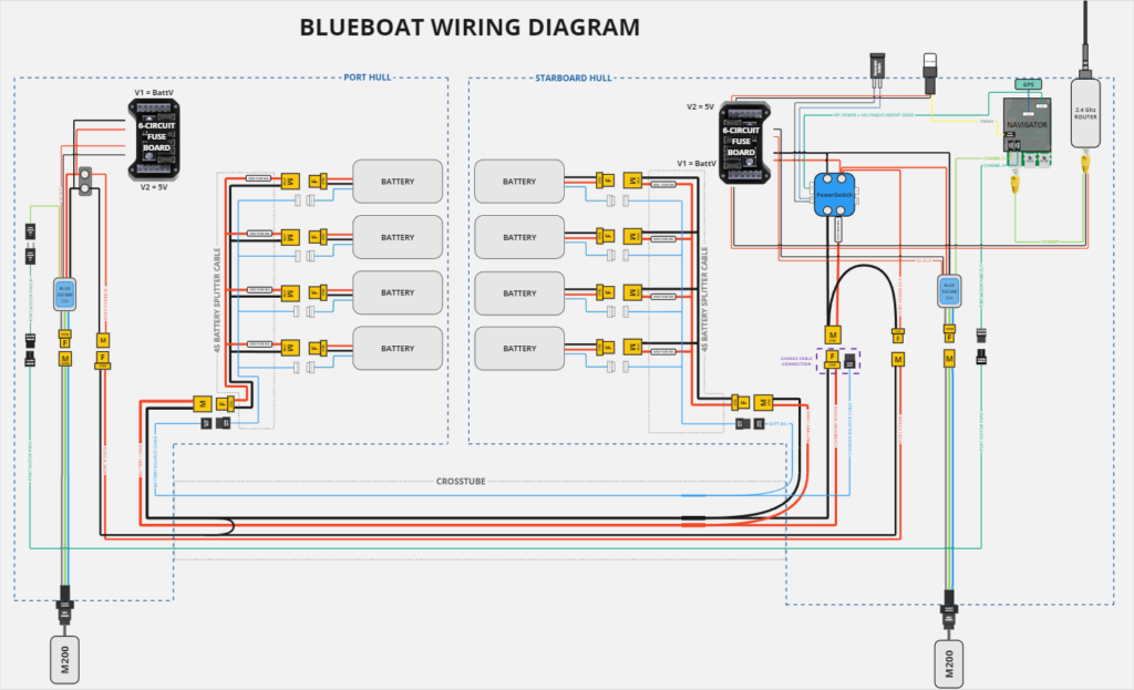
A complete BlueBoat wiring diagram is available here for reference (click for full-size PDF).
1. Connect the cables from each hatch lid assembly to the cross cable.
From the starboard hatch lid assembly (the one with the antenna connector and NavLight), you will connect:
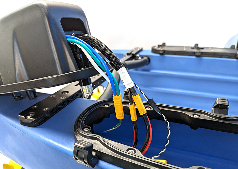
On the port side you will connect:
2. Install a 4S splitter cable in each hull. For each splitter cable, connect the female XT90 connector and the 8-pin Molex connector to the cross cable battery cable and battery balance cable in each hull. Install a cable tie around the XT90 connectors to prevent it from being disconnected.
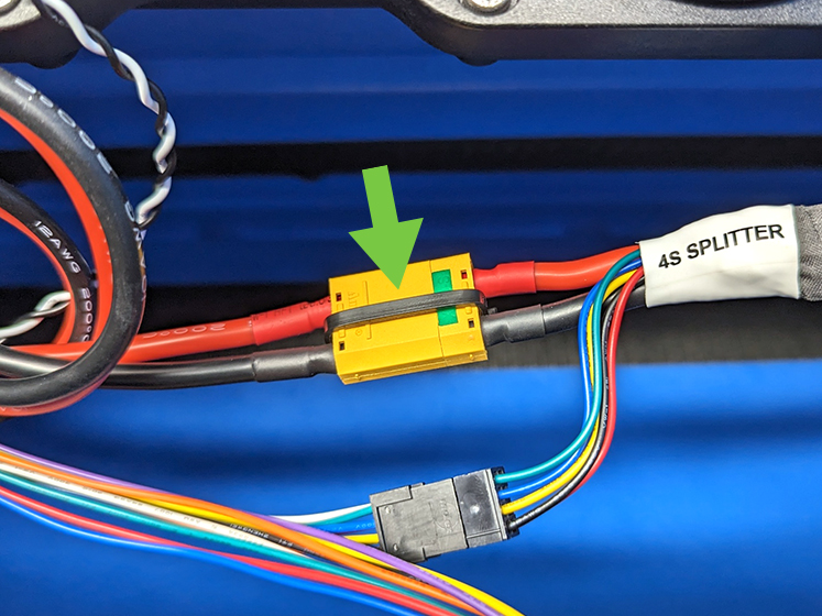
Cable tie installed around splitter cable connector.
The remaining connectors on the splitter cables are used to connect batteries and will remain unpopulated for now. The 8-pin charger balance cable on the starboard side is only used during charging and will also remain unconnected for now. Install the hatch lid assemblies in the hulls when you are done.
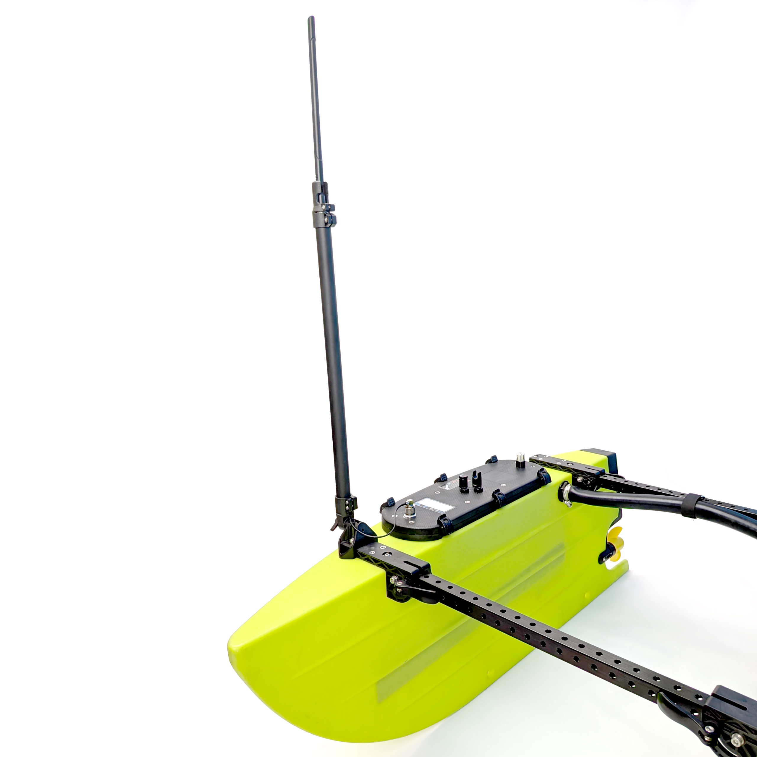
Installing the Antenna and Flagpole
To install the antenna and flagpole you will need:
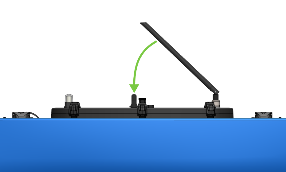
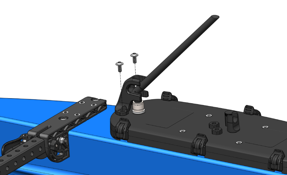
1. Screw the antenna onto the antenna connector on the starboard side hatch lid. Orient the antenna so it folds down and clips into the antenna clip.
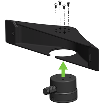
2. Coming from the front of the antenna, push the antenna guard onto the antenna and into place. Secure the antenna guard to the hatch lid using the M6x14 flanged button head screws and 4 mm hex key.
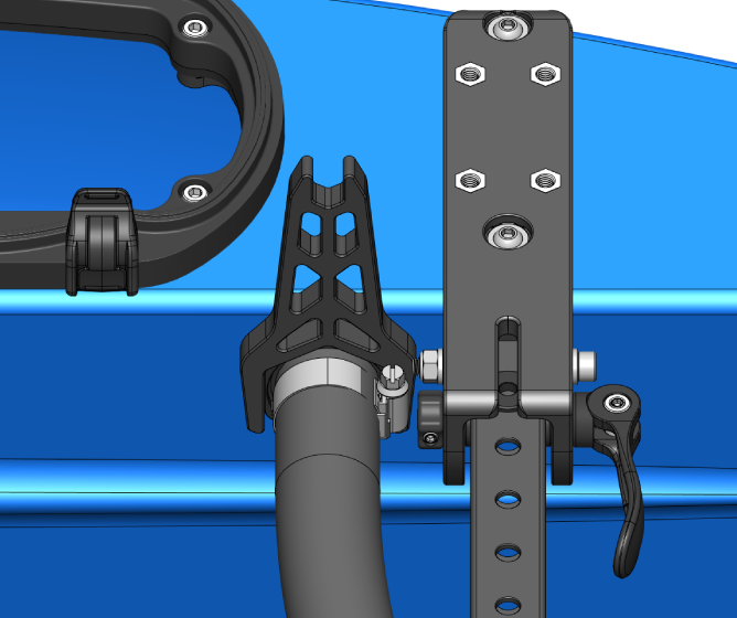
3. The flagpole mount can be installed on any of the frame bracket mounting points.
We like to install ours on the rear port side bracket, but the mounting location is ultimately up to you and whatever works best for your use. Choose a mounting location and install the flagpole mount in one of the frame bracket mounting holes to hand-tight.
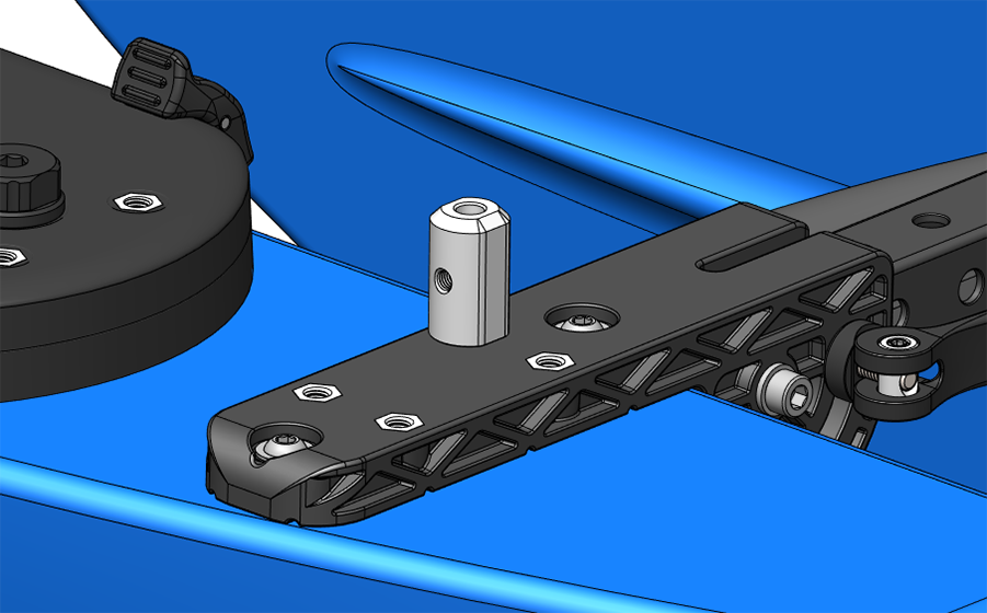
4. Insert the flagpole into the flagpole mount and use the M5x5 cup-point set screw and 2.5 mm hex driver to secure it in place.
Applying the Stickers
The bag of BlueBoat stickers contains:
The suggested locations for each sticker are shown below. Use the alcohol wipes to clean the surface before applying each sticker.
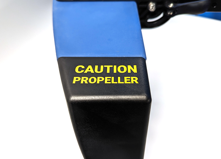
The propeller caution stickers should be applied on the top of both hull fairings, above the propellers.
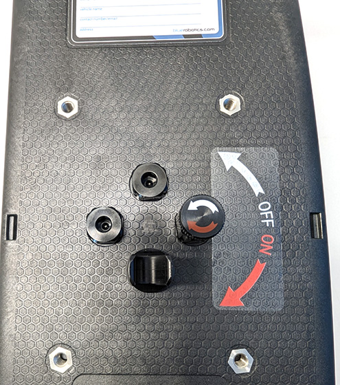
The on/off sticker should be applied to the side of the power switch on the starboard hatch lid.
The identification sticker should be applied in the rectangular depression on the starboard hatch lid.
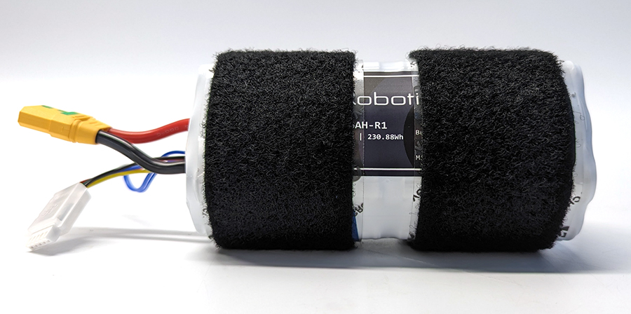
Applying Battery Velcro Strips
The supplied Velcro strips should be applied to your batteries to prevent them from shifting around inside the hulls during operation. Use the alcohol wipes to clean the surface of the batteries. Remove the backing film from the strips and apply one around each end of the battery.
Next Steps
Congrats! Your BlueBoat should now be fully assembled. Head over to the BlueBoat Software Setup guide to learn how to setup the software for your BlueBoat. After that, check out the Operator’s Guide to set out on your first mission. You can also visit the BlueBoat General Integration Guide to learn about the various ways BlueBoat supports integrating payloads.
BlueBoat Software Setup
BlueBoat Operator’s Guide
BlueBoat General Integration Guide
Adjusting Clamp Handle Force
The clamping force of the clamp handles can be adjusted to make them tighter or easier to open and close. Be aware that if the clamps are too loose, the hulls may fold inward when pressure is applied.
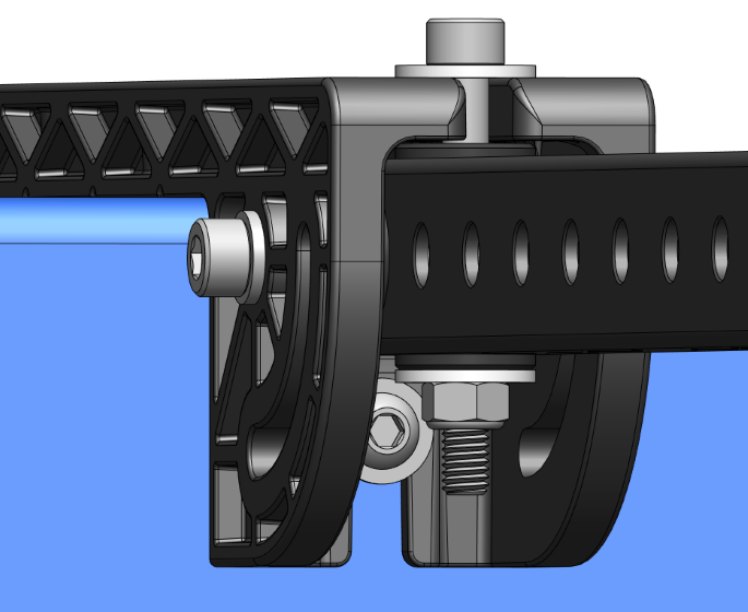
1. Use a 2.5 mm hex driver to loosen both set screws at either end of the clamp handle barrel nut.
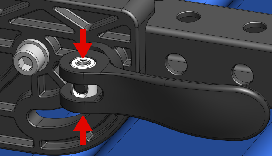
Set screw locations
2. With the set screws loosened, thread the clamp handle further onto the threaded rod to tighten or unthread it to loosen the clamping force.
3. Tighten the set screws to lock the clamp handle in place.
Fixed-frame Configuration
By default, the BlueBoat frame allows the hulls to fold inward for easier transport. The BlueBoat can also be configured with a fixed frame, making the hulls non-foldable. To set up the BlueBoat in fixed-frame configuration you will need:
All four clamp assemblies must be removed from the frame.
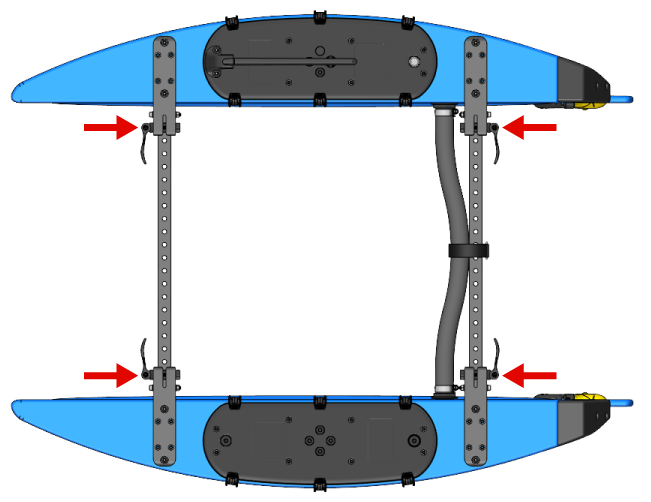
Clamp handle locations.
1. To remove a clamp, use the 2.5 mm hex driver to loosen both set screws at either end of the clamp handle barrel nut.
Set screw locations
2. With the set screws loosened, turn the clamp handle counterclockwise to remove it from the threaded rod. Hold the thumb nut at the other end of the threaded rod to prevent it from turning.
3. Repeat for the other clamps. You should end up with four clamp assemblies removed from the frame. Store these somewhere in case you want to put the BlueBoat back into the foldable configuration.
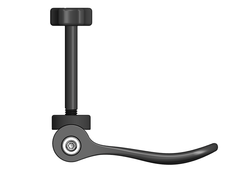
Clamp assembly.
4. Take the four frame bushings and install one in the first hole of the crossbar underneath each frame bracket.
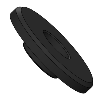
Frame bushing.
Frame bushing installed in crossbar.
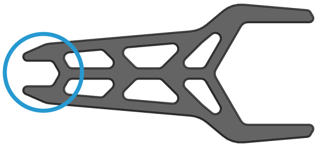
The small end of the BlueBoat Wrench can be used to hold the lock nuts for the next step.
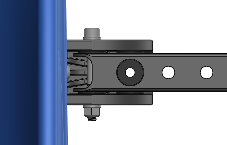
5. Install an M6x55 socket head bolt through each frame bracket, with a washer between the head of the bolt and the bracket. Secure it using a washer and lock nut. Use the BlueBoat Wrench to hold the nut while you tighten the bolt with the 5 mm hex key.
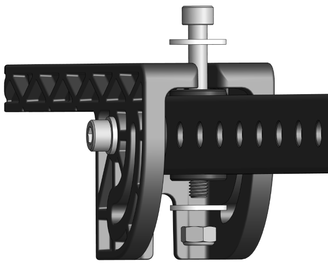
Bolt, washers, and nut.
Hardware installed in frame bracket.
BlueBoat Components Assembly
The instructions in this section show how to assemble BlueBoat components when they are purchased separately.
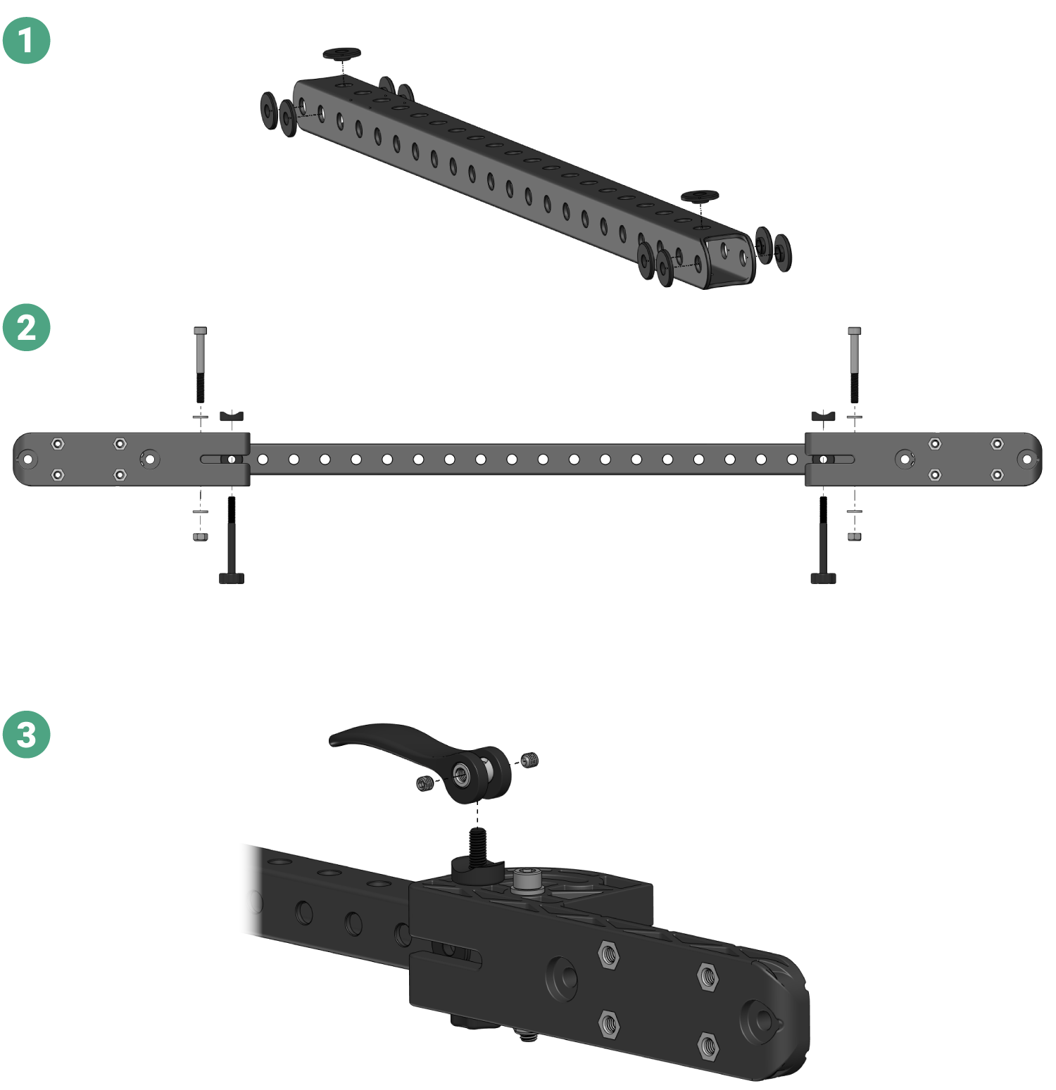
BlueBoat Crossbars and Brackets
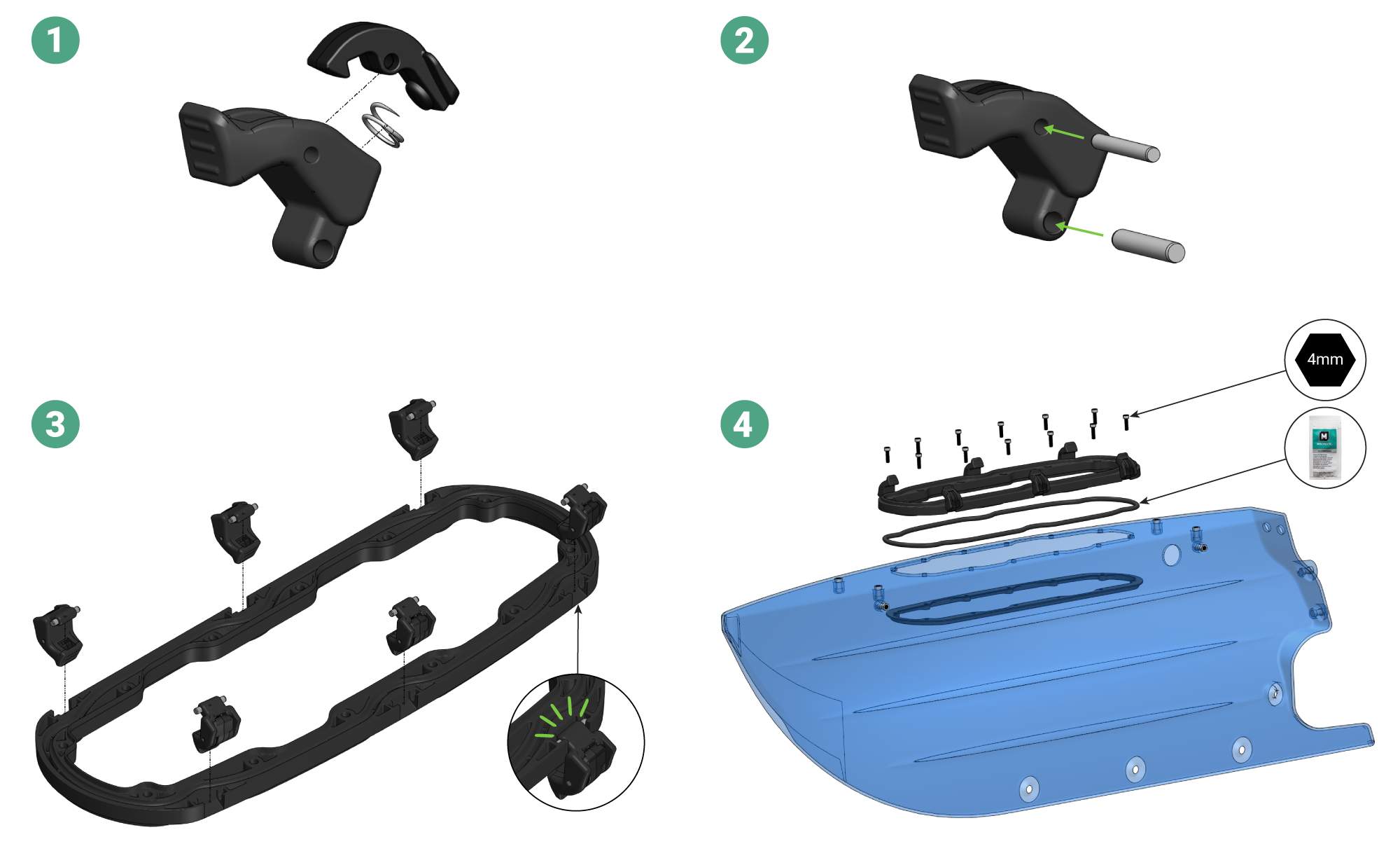
BlueBoat Hatch Base and Latches
Feedback
We’re always working to make our documentation, instructions, software, and user experience even better. If you have any ideas on how we can improve this guide, feel free to let us know here.