
Water Linked BlueROV2 Integration
Introduction
The Water Linked Underwater GPS provides global position of an underwater locator device using acoustic positioning and traditional GPS. On the BlueROV2 or other underwater vehicles it is a huge asset that allows position tracking for navigation, inspection, and mapping.
The Water Linked Underwater GPS is designed with a generic connection interface so that it can be used in a wide variety of applications, but in its stock configuration, it can be difficult to integrate with the BlueROV2. The Water Linked Underwater GPS / BlueROV2 Integration Kit provides a few components to make a seamless connection between the BlueROV2 system and the Water Linked system.
Parts and Tools
You Will Need
You will also need:
- 1 x #1 Phillips head screwdriver (BlueROV2 kit)
- 1 x Bottle of Threadlocker (not included)
Installing the Locator-A1 on the BlueROV2
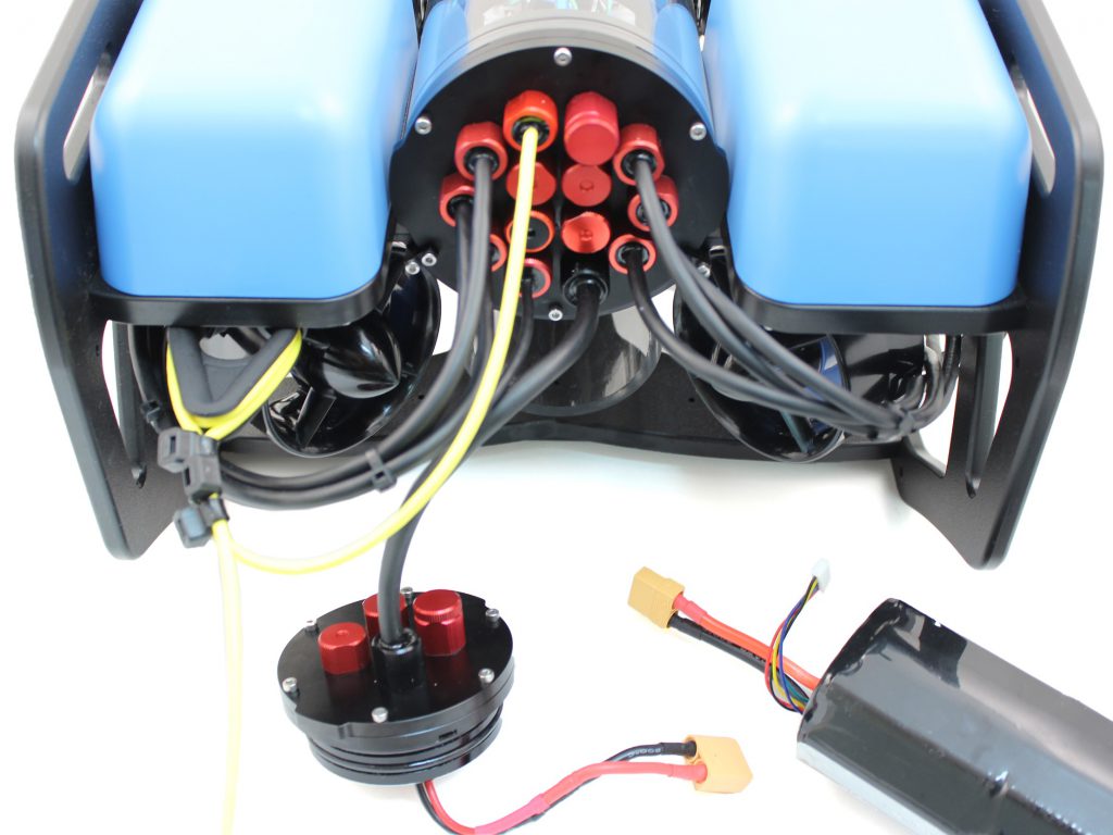
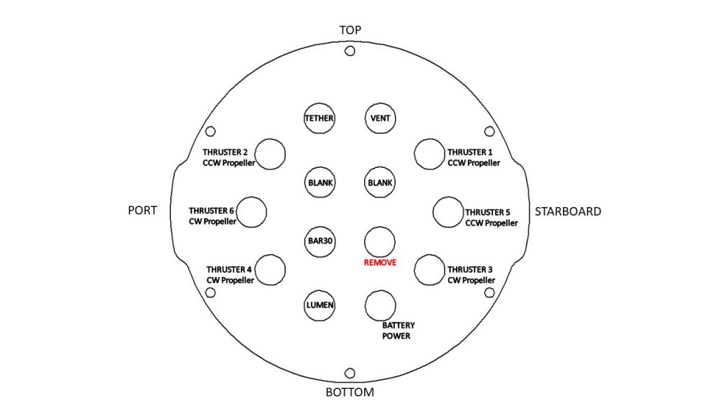
You will need to install the Analog Locator (A1) on the BlueROV2 using components from the Integration Kit. The locator will use one of the spare cable penetrations in the back of the BlueROV2 and will connect to the spare green and white twisted pair in the tether.
Removing a Blank Penetrator
To remove a blank penetrator from your BlueROV2, you will need the following tools:
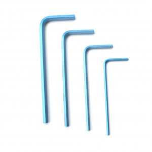
- 1 x 2.5 mm hex driver
- 1 x #1 Phillips head screwdriver
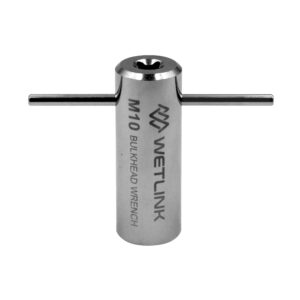
- 1 x Penetrator wrench
1. To ensure your ROV is completely powered off, please remove the battery completely from the 3” enclosure and place to the side.
2. Remove the fairings and buoyancy blocks by removing the self-tapping screws that hold the fairings to the frame.
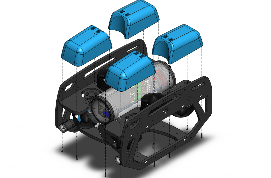
3. Remove the 4” electronics enclosure from the ROV by removing the M3x16 screws that mount the enclosure to the ROV cradle.
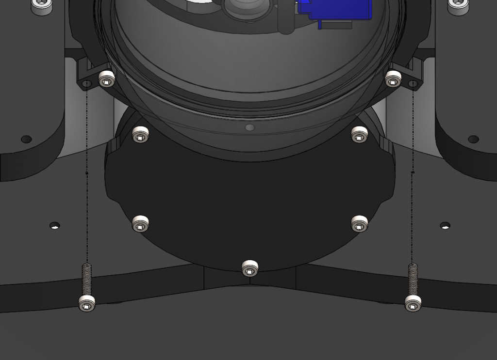
4. Remove the Vent Plug from the Vent Penetrator Bolt on the electronics enclosure. Remove the 4″ tube and forward dome assembly from the rear end cap.
5. Remove the blank penetrator as pictured from the 4” End Cap with the penetrator wrench that came with the BlueROV2 kit.
Install Locator-A1 Penetrator
To install Locator-A1 into the end cap, you will need the following parts and tools:
- 1 x Locator-A1 with pre-installed cable penetrator
- 1 x Penetrator Nut (Black)
- 1 x Penetrator O-ring
- 1 x Silicone Grease – 10g Tube
- 1 x Isopropyl Alcohol Wipe
- 1 x Penetrator wrench
1. Wipe the exterior surface of the electronics enclosure endcap clean with isopropyl alcohol or isopropyl alcohol wipes, and make sure it is free of any particles in the areas where the penetrator O-ring will sit.
2. Remove the O-ring from the bag and apply silicone grease to it.
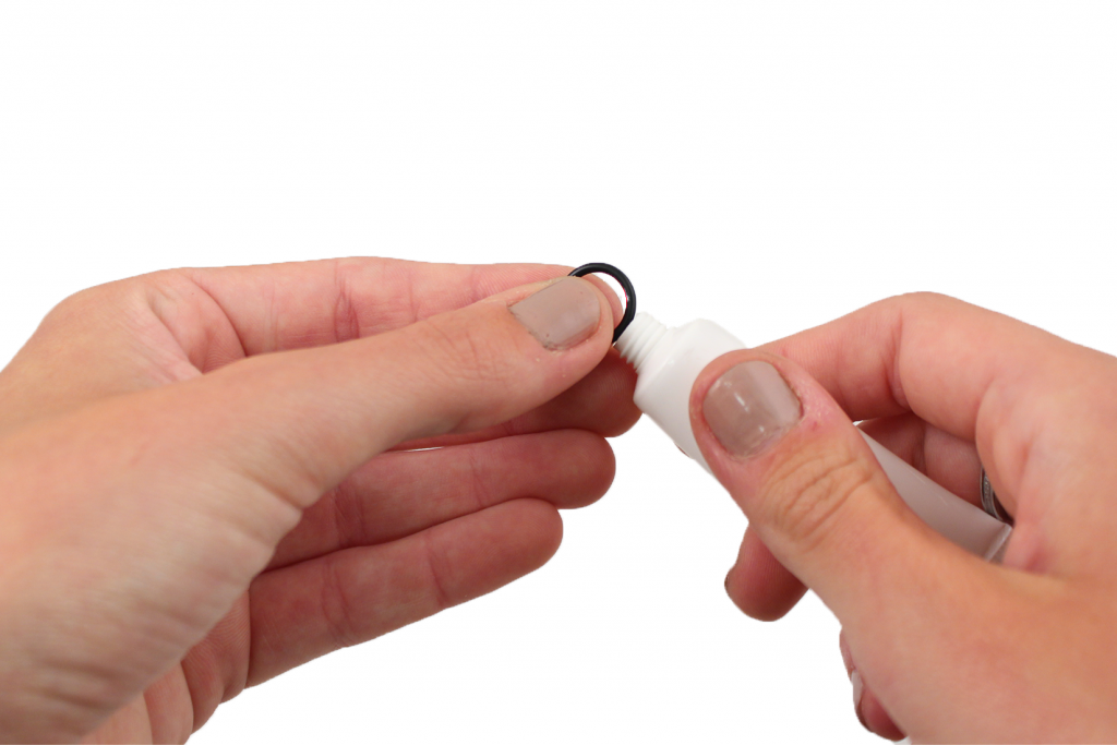
3. Install the O-ring onto the Locator-A1 cable penetrator.
4. Install the Locator-A1 cable penetrator on to the end cap in the hole you previously removed the blank penetrator from. Tighten to finger tight, then use the provided wrench to tighten it an additional ~1/16 of a turn. If you can’t loosen it with your fingers, it is tight enough.
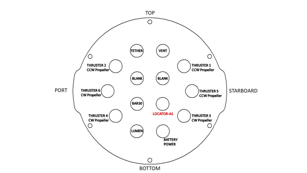
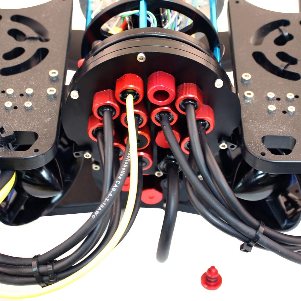
5. Using the pre-crimped header pin connector on the Analog Locator, connect the locator wires (green/white) to a spare twisted pair of the tether (green/white).
Reassemble BlueROV2 Electronics Enclosure
To reassemble your BlueROV2 Electronics Enclosure, you will need the following parts and tools:
- 4 x M3x16 screws that were placed off to the side during disassembly
- 1 x Silicone Grease – 10g Tube
- 1 x 2.5 mm hex driver
Reinstall 4” Watertight Enclosure onto ROV with the following steps:
1. Apply silicone grease to the two radial O-rings on the O-Ring Flange (4” Series) that is attached to the Electronics Tray then install the Watertight Enclosure (4” Series) with installed Dome End Cap to the O-Ring Flange (4” Series).
2. Mount the Electronics Enclosure to the frame using the M3x16 screws so that the dome is on the same side as the front center panels (the center panels without the 3 large holes). Install the M3x16 screws through the clips and into the Enclosure Cradle (4” Series). It is easier to install these screws if the clips are not fully tightened until all screws are through the clips and threading into the Enclosure Cradle (4” Series). This allows to clips to rotate so you can find the threaded hole in the Enclosure Cradle (4” Series) easily.
Mounting the Locator-A1 to the BlueROV2 Frame
To mount the Locator-A1 to the BlueROV2 frame, you will need the following parts and tools:
- 1 x Aluminum Locator-A1 mounting bracket (2 halves)
- 4 x M3x16 socket head cap screws
- 2 x M5x12 button head cap screws
- 1 x 2.5 mm hex driver
- 1 x 3 mm hex driver
- 1 x Bottle of Threadlocker
1. Route the locator to one side of the ROV.
2. Attach the included aluminum mounting bracket to the Locator-A1 using the M3x16 socket head screws.
3. Secure the mounting bracket to the existing holes on the ROV frame.
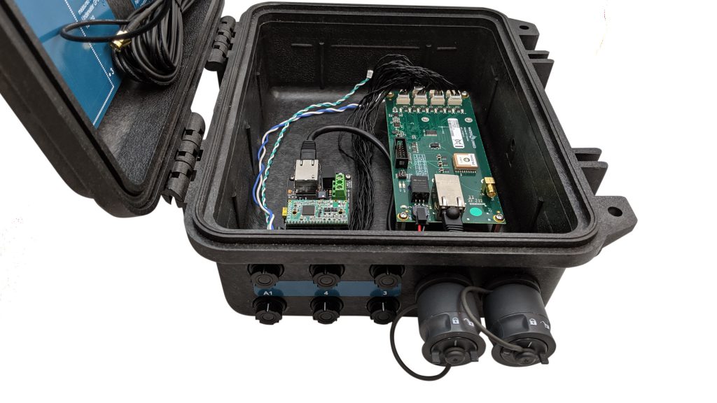
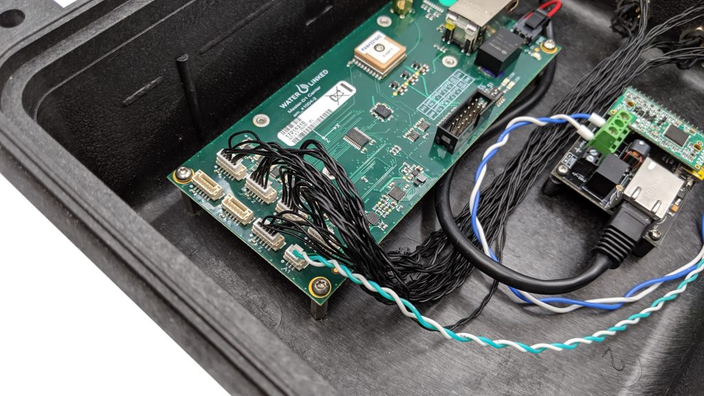
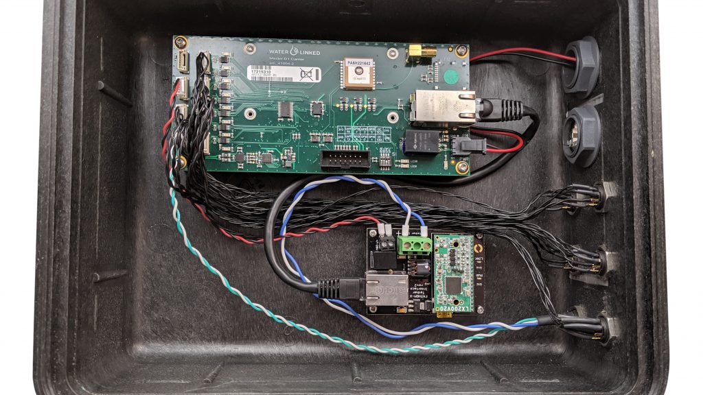
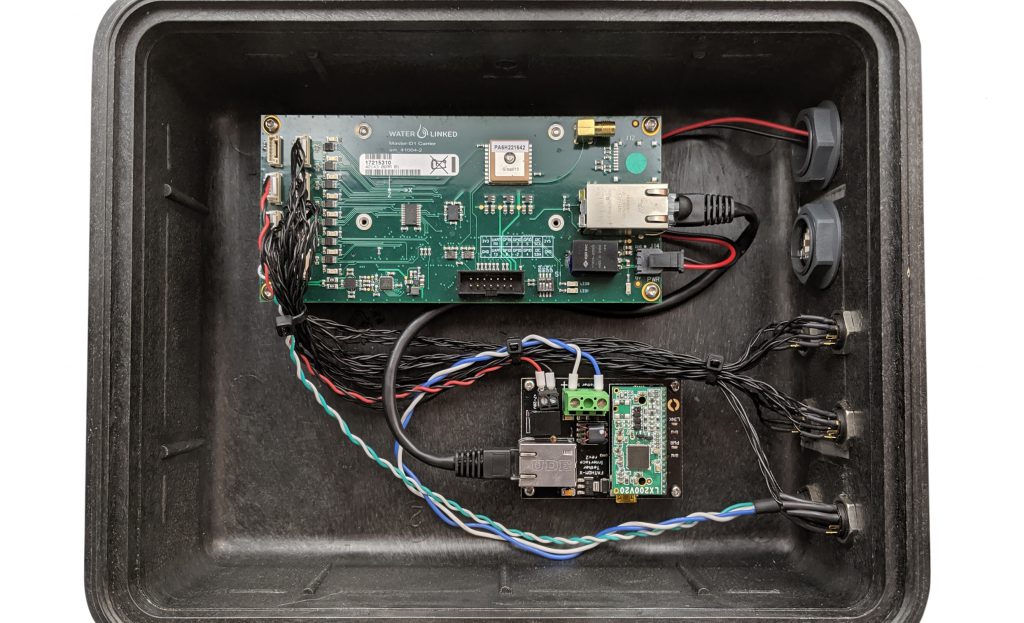
Modifications inside the Water Linked Box
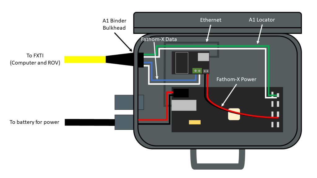
Inside the Water Linked box, we’ll be adding a Fathom-X tether interface board and a few cables to make integration seamless. This Fathom-X board will be added in addition to the Fathom-X board that is already used in the FXTI. The two boards are connected in parallel to the same twisted pair, putting the ROV, topside computer, and Water Linked box on the same computer network.
Here’s a diagram of what we’ll be connecting inside the box:
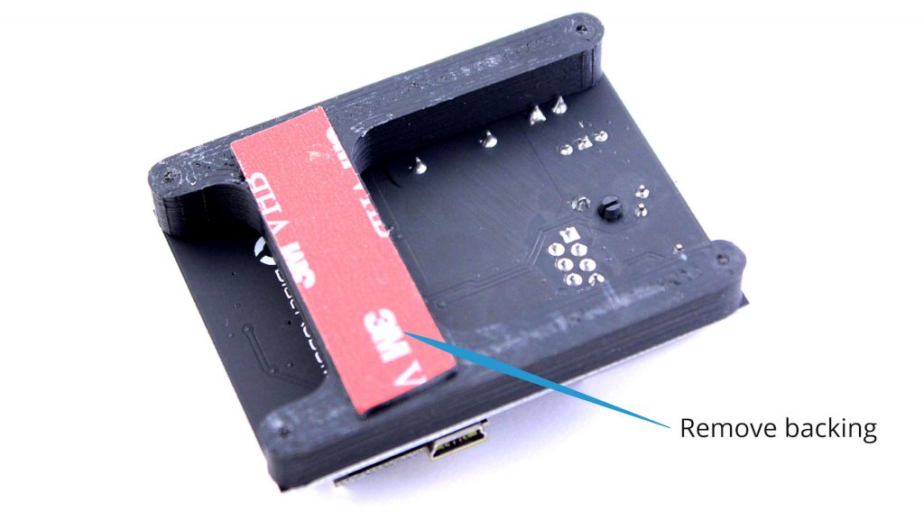
1. Remove the backing from the red 3M VHB tape on the back of the Fathom-X mount.
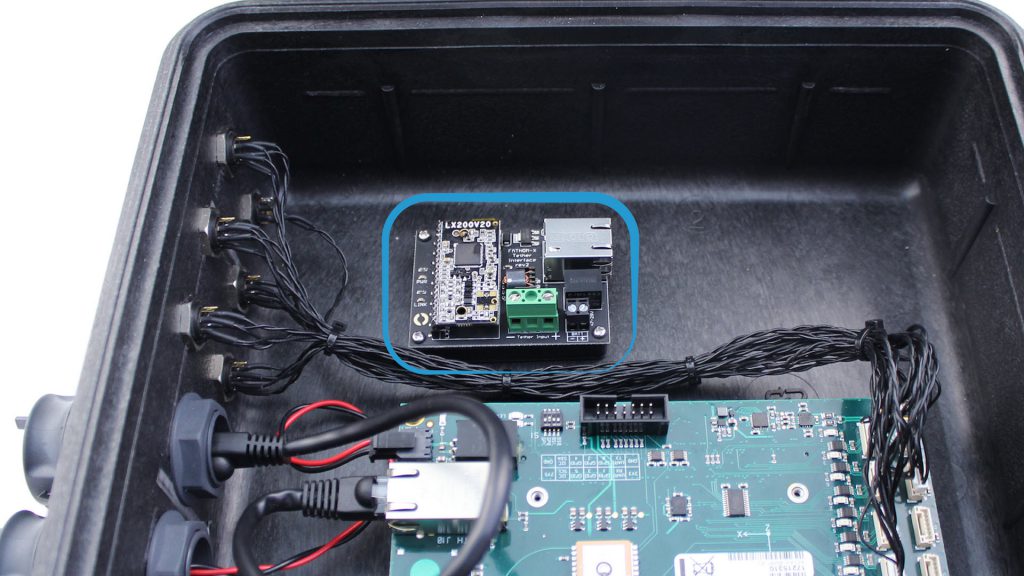
2. Install the Fathom-X board in the Water Linked box as shown below.
3. Unplug the Ethernet cable from the connector on the side of the box, route underneath the Water Linked board, and plug into the Fathom-X module.
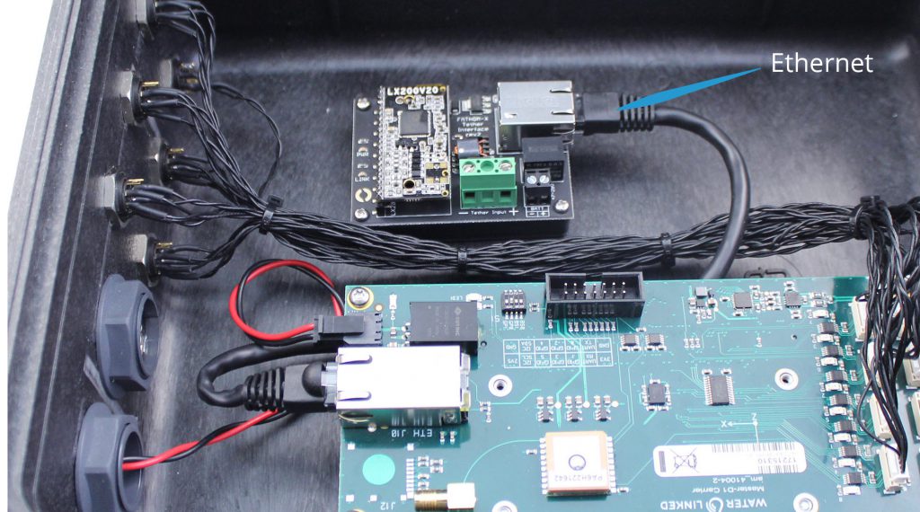
4. Unplug the small A1 plug from the top right corner of the Water Linked board.
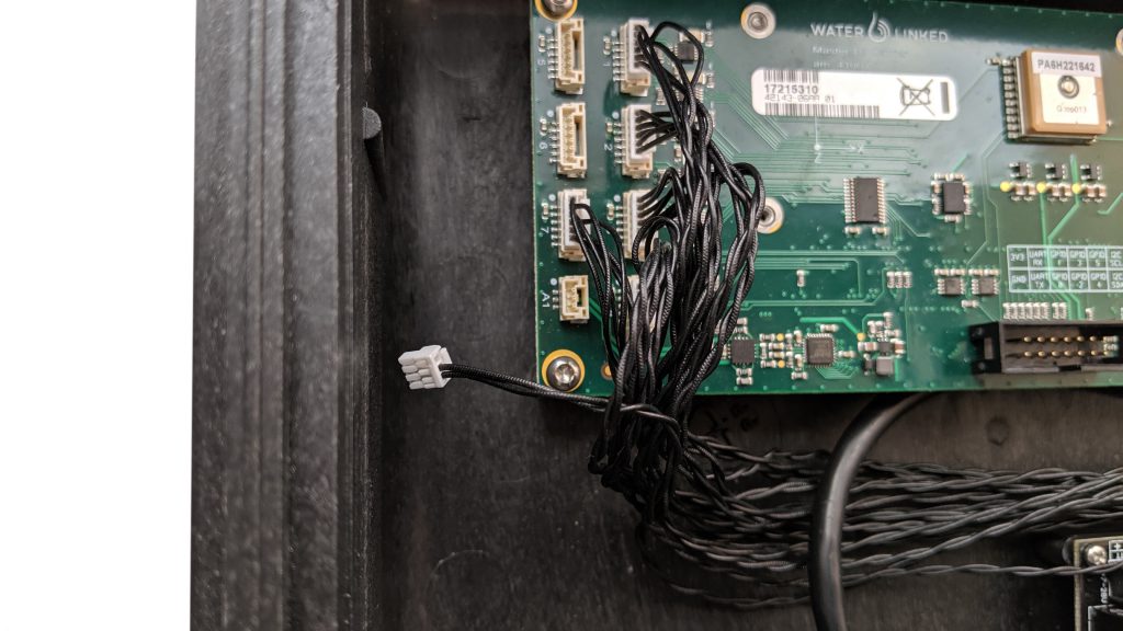
4. Carefully remove the zipties holding the black wires together. Remove the “A1” bulkhead connector from the side of the box.
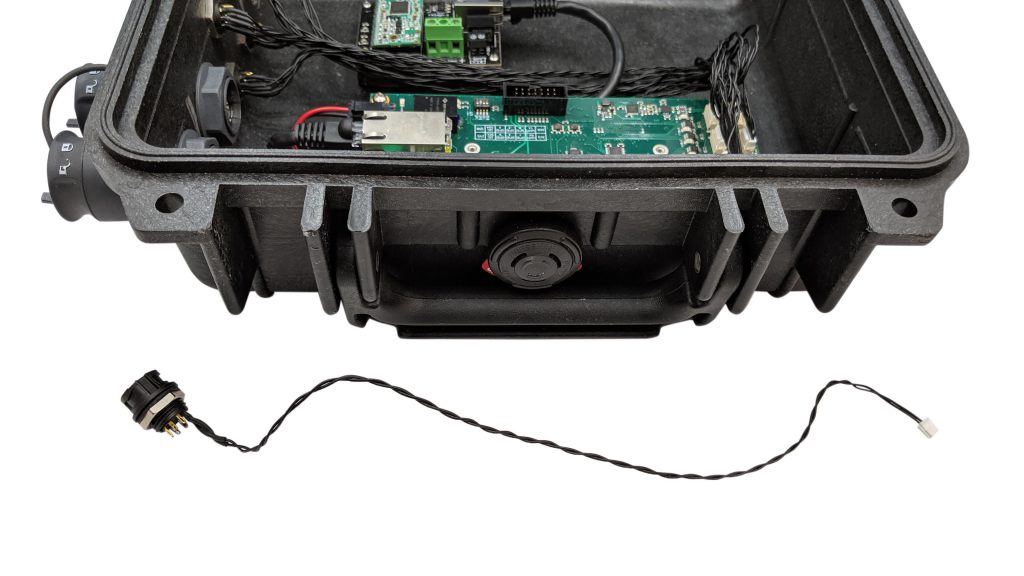
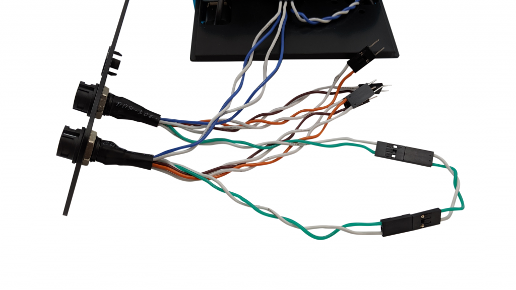
5. Install the new bulkhead connector with blue/white and green/white pairs into the same hole, making sure the line on the connector body is facing upwards.
6. Using a small flathead screwdriver, connect the blue and white wires to the positive and negative tether input terminals on the Fathom-X board.
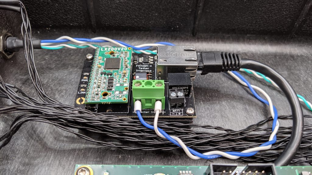
7. Plug in the new A1 plug with green and white wires into the A1 receptacle.
8. Plug the Fathom-X power cable into port D5 or D6 on the Water Linked board. Then connect the ferrules on the other ends of those wires to the positive and negative power input on the Fathom-X board (black terminal block). Be sure the polarity is correct or you will damage the power regulator on the Fathom-X board.
9. Add a zip tie to the wiring harness to keep all wires tidy.
Nice job! You’re done with modifications to the Water Linked box. Up next, we’ll show you how to connect the box to your FXTI.
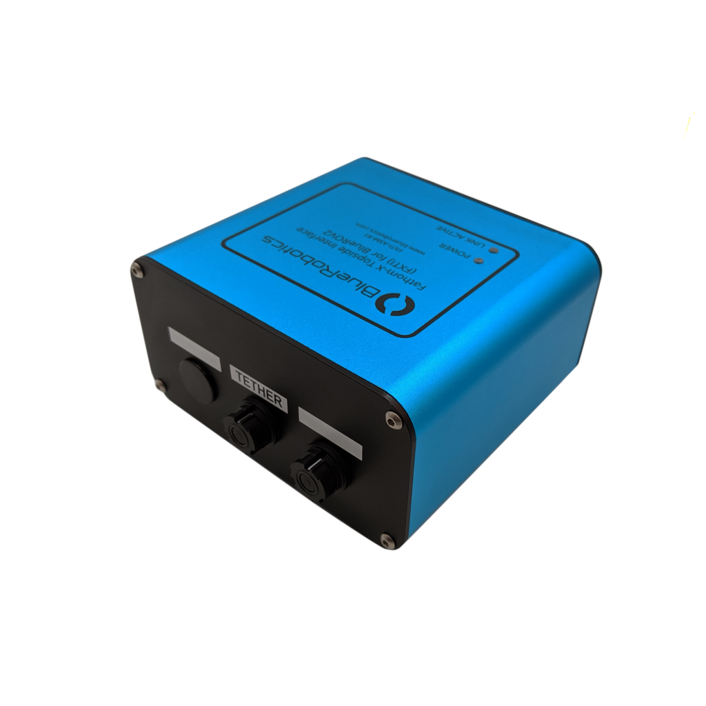
Modifications to FXTI
The connections made inside the FXTI will connect the ROV, Topside Computer, and Water Linked systems to each other. Here’s a high level diagram of what that will look like:
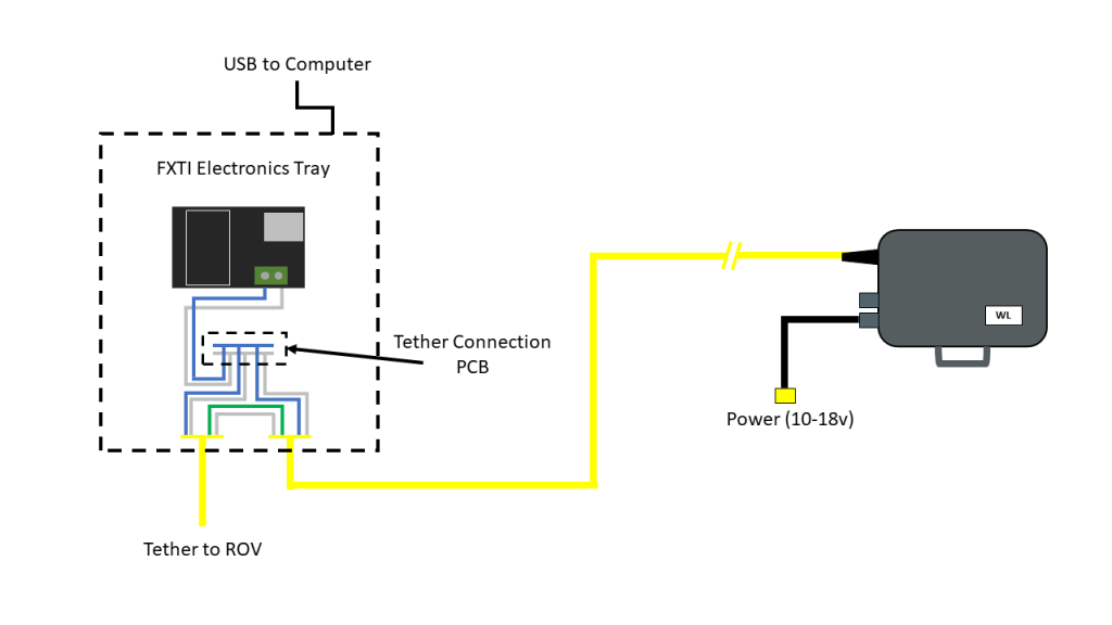
The connections are made on the Tether Connection PCB on the FXTI Electronics Tray and connecting the green Locator-A1 wires.
1. Remove one of the black plastic FXTI plugs from one of the auxiliary ports.
2. Thread the FXTI Binder pigtail wire assembly into the open port and secure in place with the included bulkhead nut.
3. Connect the blue and blue/white wire pair into the FXTI Tether Connection PCB matching the orientation of the pre-installed blue and white wire connections.
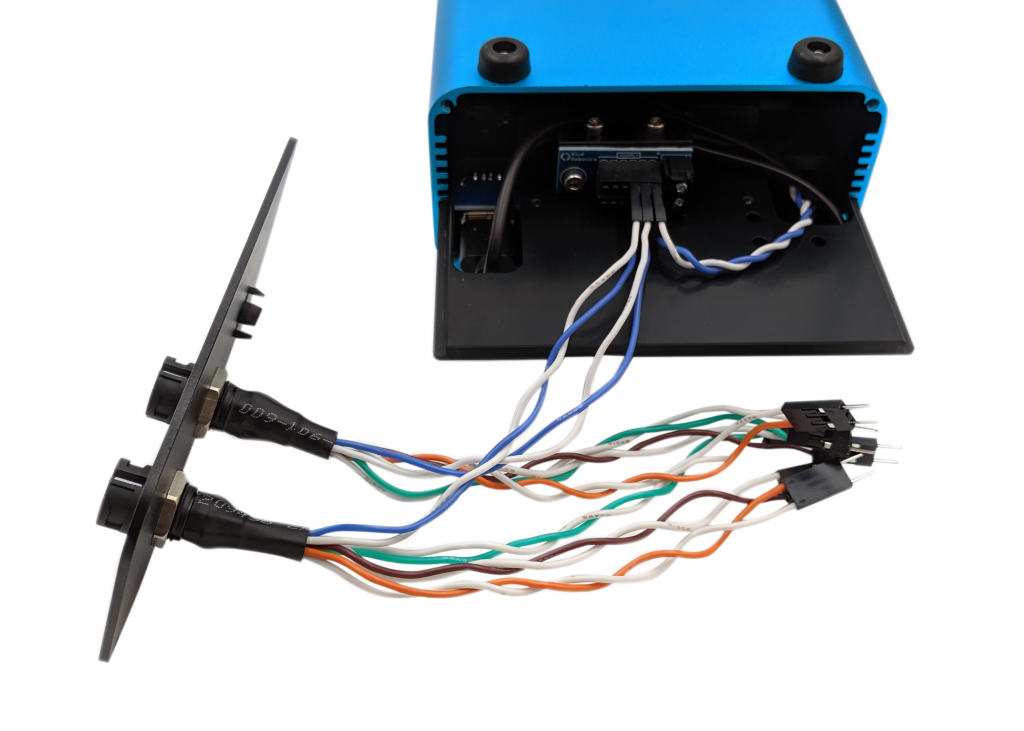
4. Connect the green and green/white Locator-A1 wire pair into the green and white pair on the Binder connector pigtail, matching colors, with the included female-to-female adapter.
5. Reassemble the FXTI box.
ArduSub Software Update
Software Setup
1. Configure the Water Linked system with a static IP address of 192.168.2.94 according to the Network section of the Water Linked Documentation.
2. Connect the topside computer to the FXTI. Connect the BlueROV2 to the FXTI and power the BlueROV2 normally.
3. Connect the FXTI to the Water Linked Box using the 8m deck extension cable from the Integration Kit.
4. Follow the Quickstart from the Water Linked Documentation for:
- Powering the Water Linked box.
- Calibrating the IMU.
- Deploying receivers.
- Making Receiver-D1 connections to the box.
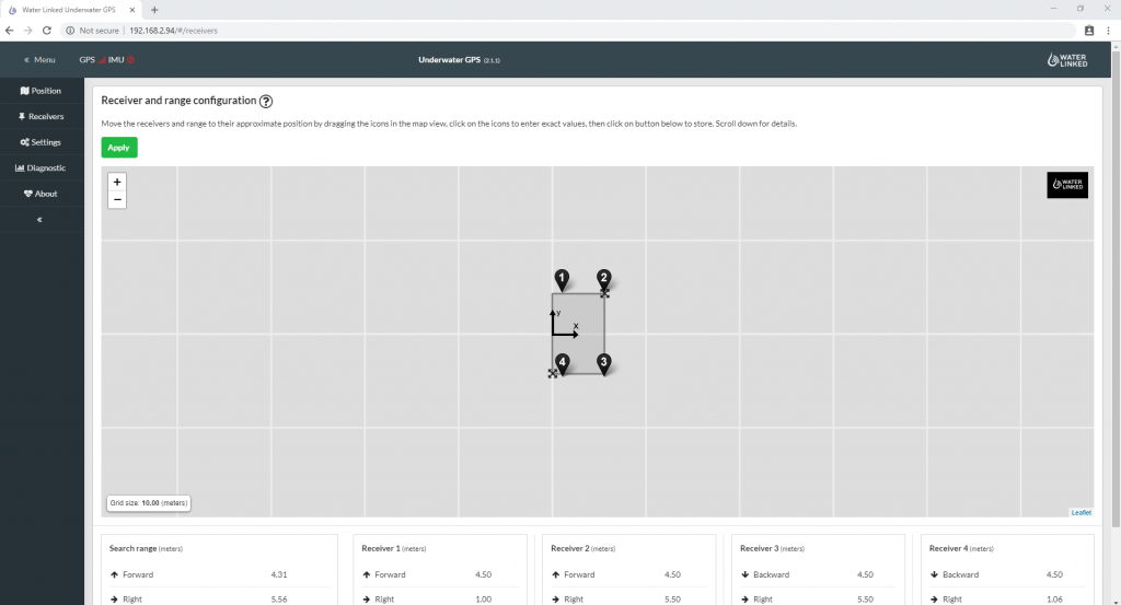
5. To configure the receiver location Water Linked Underwater GPS system, navigate to http://192.168.2.94/#/receivers in your browser. Please refer to the Receivers section for further information on configuration.
6. Power on the BlueROV2 and dive so the Locator-A1 is submerged a few inches below the surface.
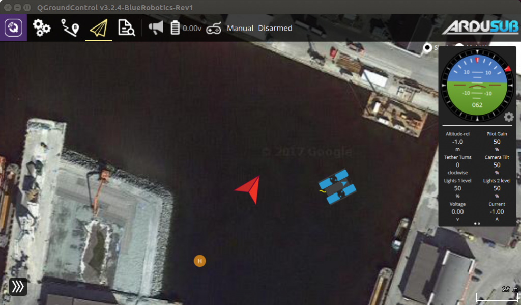
7. If everything is operating correctly, you should now find an ROV position on the map in QGroundControl. The ROV position is indicated by a BlueROV2 image. The position of the surface vessel or Water Linked Master Electronics box is indicated by a red arrow. The small ‘H’ icon indicates the ‘home position’, the location of the ROV’s first GPS lock.
Troubleshooting
No External Depth Error
If the error message “No external depth received. Is it being sent correctly?” is displayed in the UGPS UI, then conduct the following:
1. Ensure you are using the latest versions of ArduSub Companion and QGroundControl: Update Software
2. In the Companion Web Interface, go to the MAVProxy page: http://192.168.2.2:2770/mavproxy
3. Click on the “Restore Default Options” button.
4. Power Cycle the BlueROV2.
Water Linked Software Update
Check the Water Linked system for available software updates. You can check the Underwater GPS software version at 192.168.2.94/#/about. The update process is documented in the Software Update section.