
Ethernet Switch Installation Guide for the BlueROV2
Introduction
The Ethernet Switch is a compact switch that integrates perfectly with the Fathom-X Tether Interface Board and the BlueROV2. It improves expandability on the ROV by providing three additional Ethernet ports to connect Ethernet devices such as sonars, IP cameras, and more.
Parts and Tools
You Will Need
You will also need:
- #1 Phillips screwdriver
- #2 Phillips screwdriver (one is included with BlueROV2 kit)
- 2.5 mm hex driver (one is included with BlueROV2 kit)
- 2 mm hex key (one is included with BlueROV2 kit)
- Small (~2 mm) flat head screwdriver
BlueROV2 Installation
Opening the Electronics Enclosure
To open the Electronics Enclosure, you will need:
- 2.5 mm hex driver
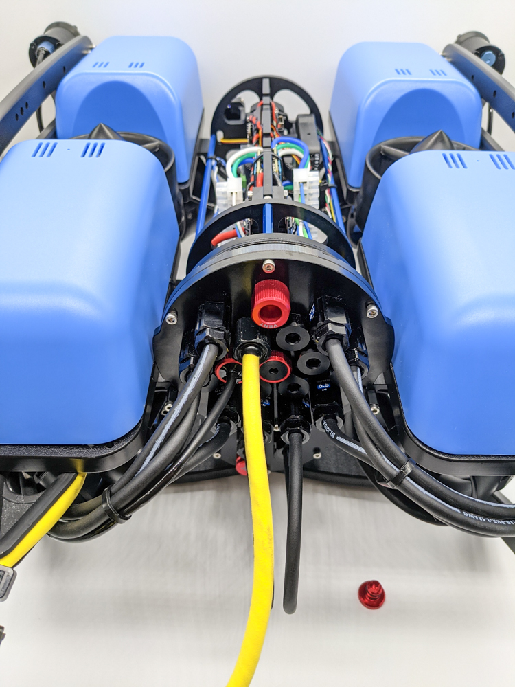
1. Ensure the ROV is completely powered off by disconnecting the battery from the battery power cables.
2. Use the 2.5 mm hex driver to remove the M3x16 screws that mount the Electronics Enclosure to the ROV enclosure cradles.
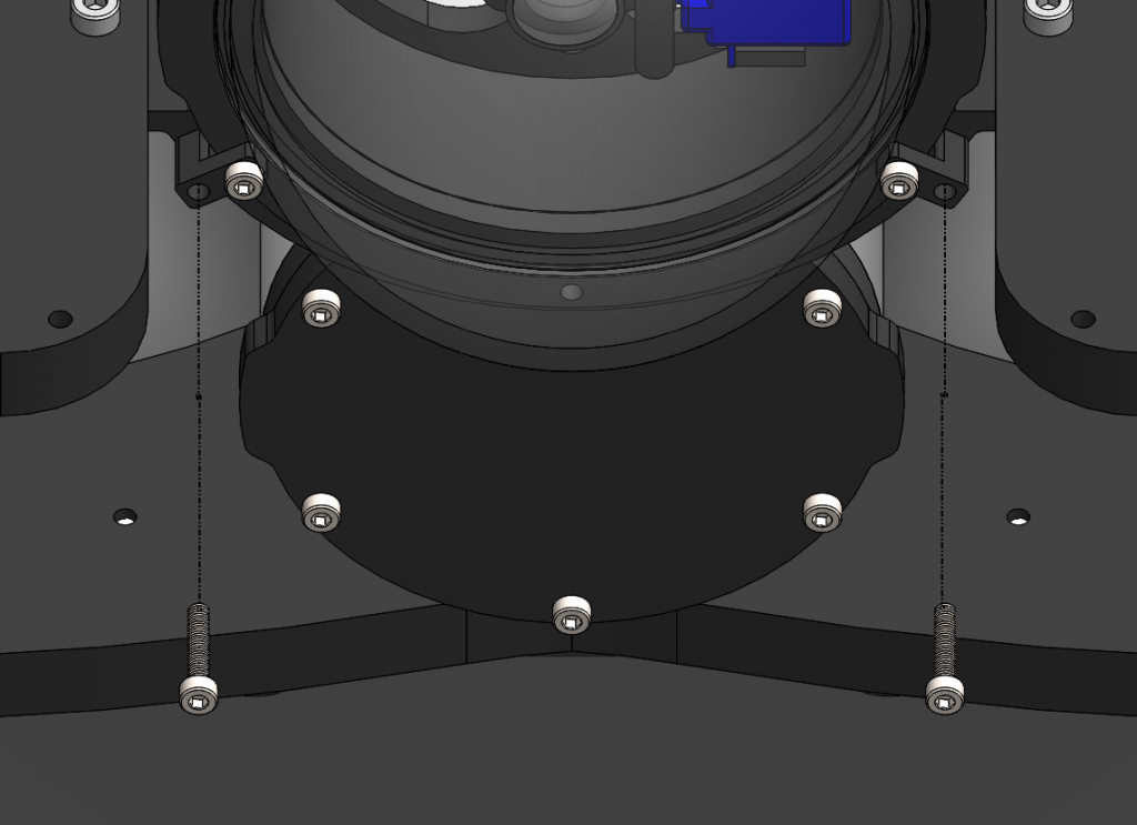
3. Remove the vent plug from the vent penetrator bolt on the Electronics Enclosure. Remove the 4″ series tube and dome from the end cap flange assembly to access the inside of the Electronics Enclosure.
Installing the Ethernet Switch
To install the Ethernet Switch in the ROV you will need:
- 2 x 18 mm mounting standoffs
- 4 x M3x5 button head mounting screws
- 1 x 150mm Ethernet cable
- 1 x Power cable with spade connectors
- #1 Phillips head screwdriver
- #2 Phillips head screwdriver
- 2 mm hex key
- Small (~2 mm) flat head screwdriver
- Wire cutters or scissors
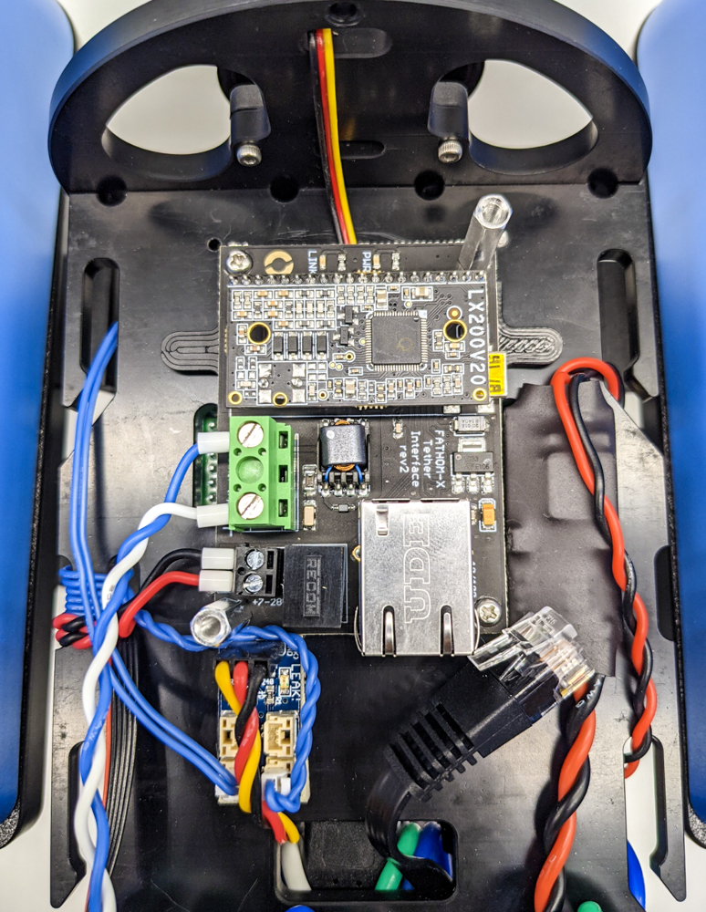
1. Use the #1 Phillips head screwdriver to remove the four #3-28 mounting screws from the Fathom-X Tether Interface Board. There are two plastic spacers underneath the Fathom-X Tether Interface Board, set these and the four mounting screws to the side.
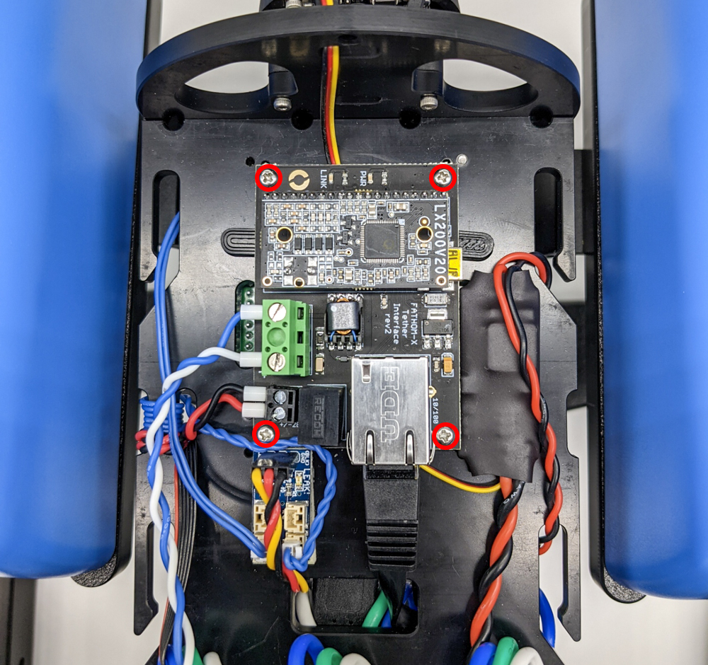
2. Disconnect the Raspberry Pi Ethernet cable from the Fathom-X Tether Interface Board. You can also disconnect the tether extension cable and power cable to give you better access to the bottom of the board. Use the small (~2 mm) flat head screw driver to loosen the terminal screws to allow you to disconnect the cables.
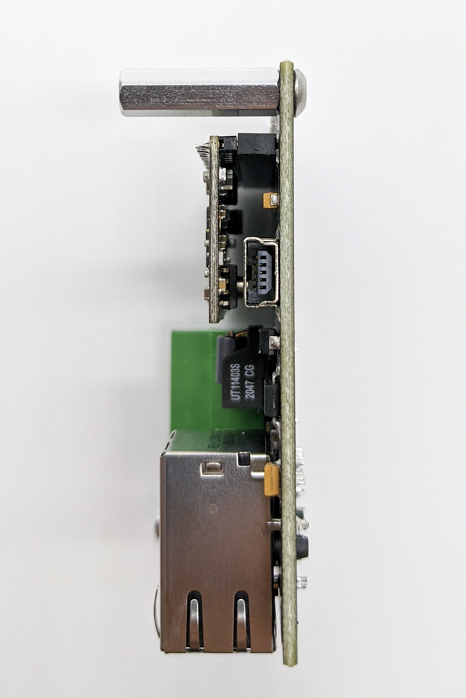
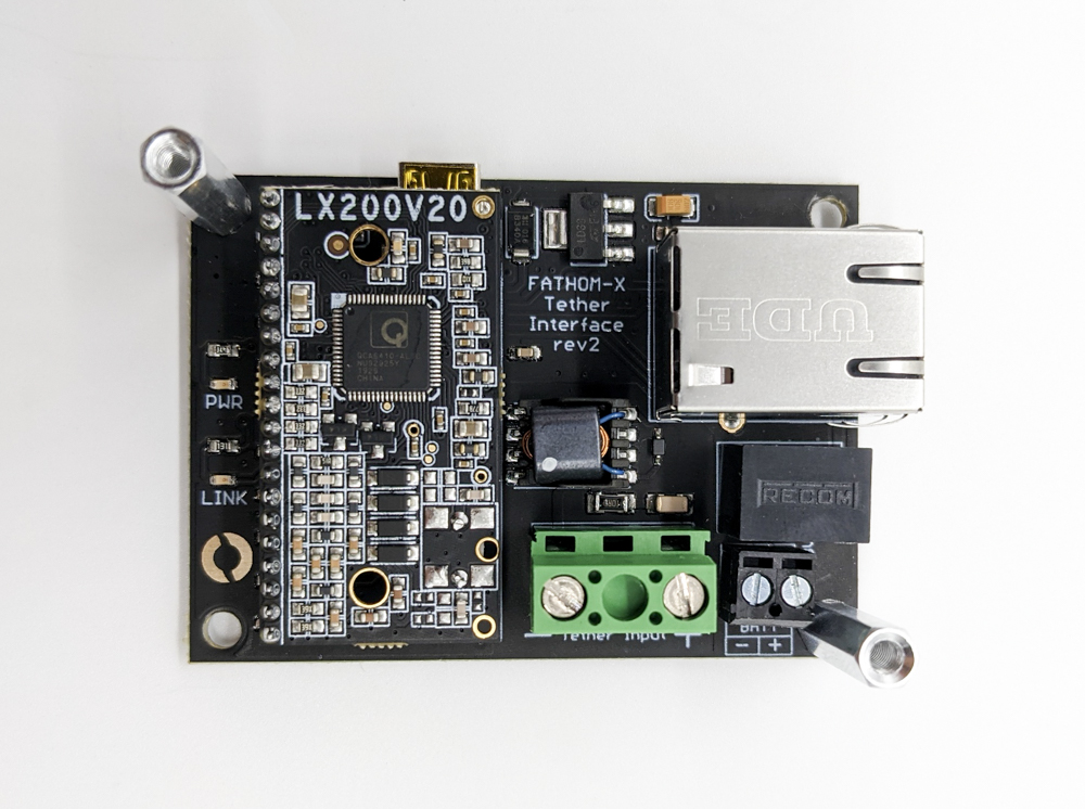
3. Use two of the M3x5 button head mounting screws and 2 mm hex key to install the two 18 mm mounting standoffs on opposite corners of the Fathom-X Tether Interface Board.
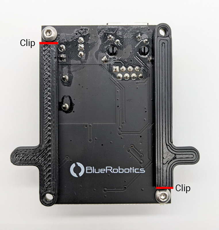
4. Align the plastic spacers that were set aside earlier to the mounting holes on the Fathom-X Tether Interface Board. Use wire cutters or scissors to clip off one end of each spacer so it does not interfere with the button head mounting screw when mounting the board back on the Electronics Tray.
5. Reinstall the Fathom-X Tether Interface Board and plastic spacers to the mounting holes on the Electronics Tray using two of the #3-28 mounting screws you set aside previously. After this step there will be two #3-28 mounting screws left over that will not be used. If the tether extension cable and power cables were disconnected previously, reconnect them to the proper terminals before moving on to the next step.
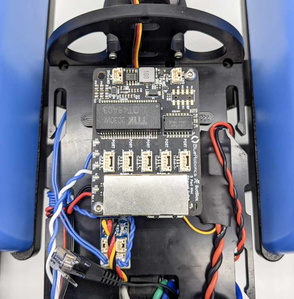
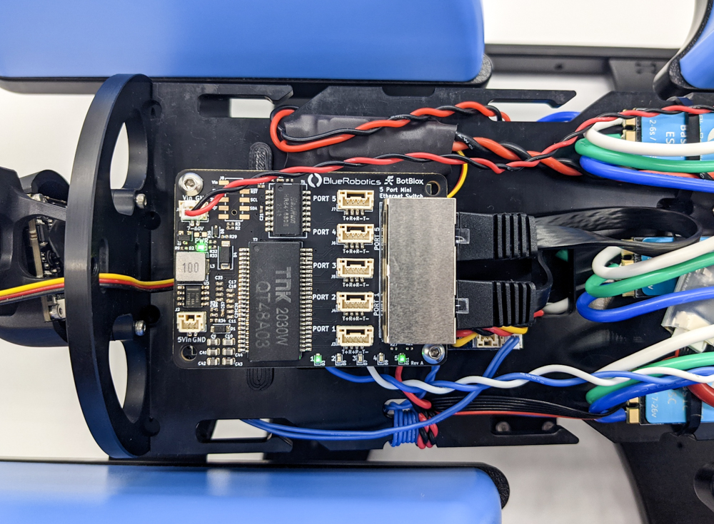
6. Use the remaining two M3x5 button head mounting screws and 2 mm hex key to install the Ethernet Switch on top of the Fathom-X Tether Interface Board. The RJ45 (Ethernet) jacks on the Ethernet Switch should be on the same side as the RJ45 jack on the Fathom-X Tether Interface Board.
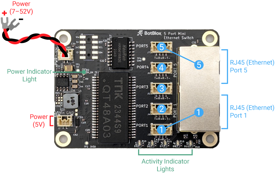
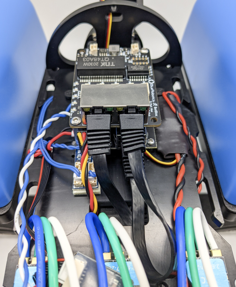
7. Connect the 150 mm Ethernet cable to the RJ45 (Ethernet) jack on the Fathom-X Tether Interface Board and connect the other end to the right RJ45 jack (port 5) on the Ethernet Switch. Connect the Raspberry Pi Ethernet cable to the left RJ45 jack (port 1) on the Ethernet switch.
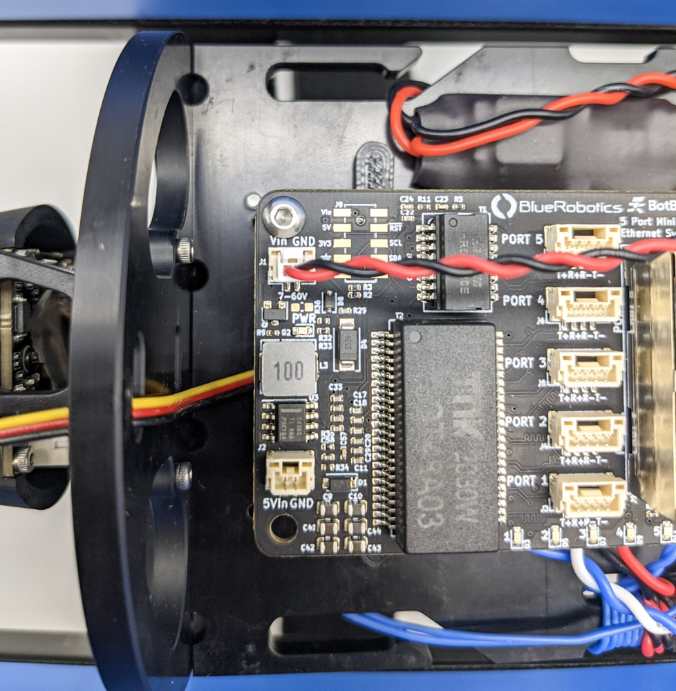
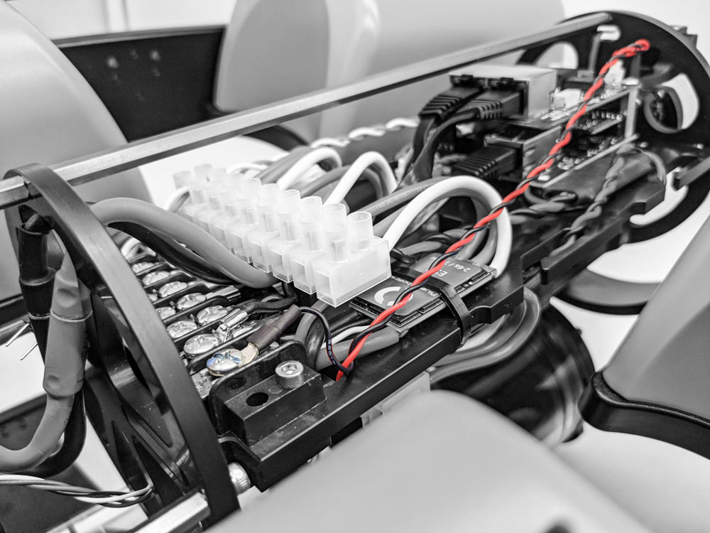
8. Connect the power cable to the “PWR 7-52V” JST-GH connector in the top left of the Ethernet Switch board.
9. Use the #2 Phillips head screwdriver to connect the spade connectors at the end of the power wires to available screw terminals on the power terminal blocks. Connect the black power wire to the terminal block with the rest of the black wires and connect the red power wire to the terminal block with the rest of the red wires. Use the cutout in the Electronics Tray to route the power wire to the terminal block on the other side.
10. Now is a good time to test your connection before connecting any additional devices. Power on the ROV by connecting the battery to the battery power cable. The “5V_OK” indicator LED on the Ethernet Switch should illuminate and the activity indicator LEDs for ports 1 and 5 should show some activity after a few seconds. Connect the ROV to you topside computer and test if you are able to establish a connection. If everything is working normally, you are now ready to connect other devices to your Ethernet Switch! If there is a problem establishing a connection, proceed to the Troubleshooting section below.
Connecting Devices
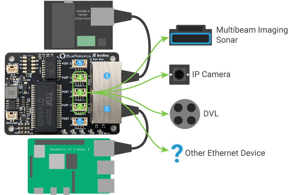
The Ethernet Switch is an unmanaged switch so no additional configuration is required. Just connect a device and the switch will automatically begin forwarding packets.
There are a total of 5 ports on the Ethernet Switch. Ports 1 and 5 are each broken out to both a JST-GH connector and an RJ45 jack. When installed in a BlueROV2, the Fathom-X Tether Interface board and Raspberry Pi are connected to ports 1 and 5 via the RJ45 jacks. This leaves ports 2, 3, and 4 open to connect other Ethernet devices.
JST-GH Connector Pinout
The JST-GH connectors for ports 1-5 follow the Blue Robotics Connector Standard for Ethernet connections:
| Recommended Connector | Pin # | Signal | Recommended Wire Colors |
|---|---|---|---|
| JST GH (4 position) Part #: BM04B-GHS-TBT(LF)(SN)(N) SM04B-GHS-TB(LF)(SN) | 1 | TX+ | White/orange |
| 2 | RX+ | White/green | |
| 3 | RX- | Green | |
| 4 | TX- | Orange |
Cable Connections
An RJ45 to JST-GH adapter board is included in the Ethernet Switch kit.
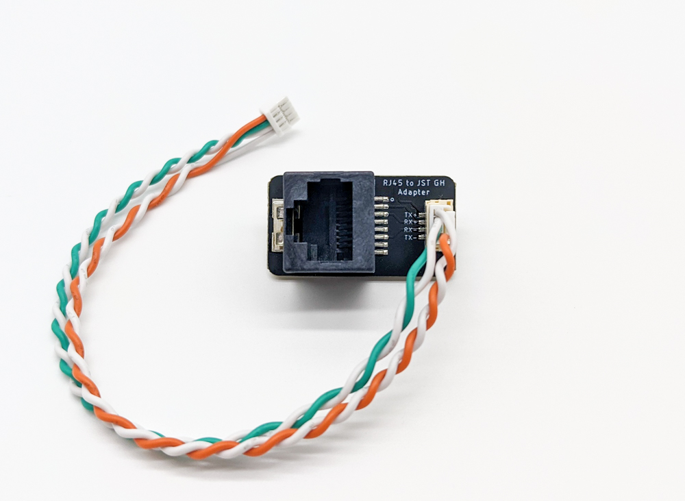
RJ45 to JST-GH adapter
This adapter makes it easy to connect your Ethernet devices for initial testing. Additional RJ45 to JST-GH Adapter Boards can be purchased separately here.
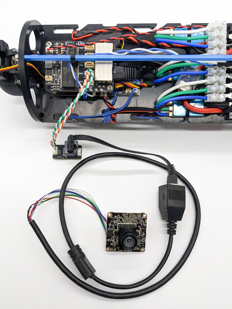
Testing an IP camera using the RJ45 to JST-GH adapter.
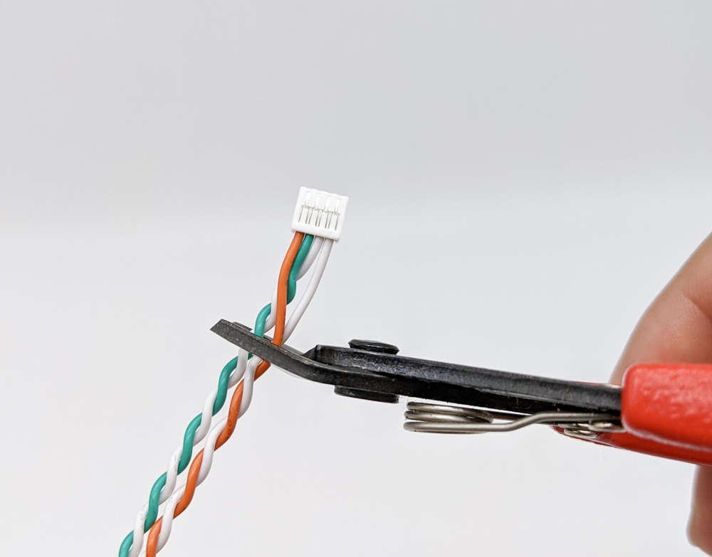
For long term integration or integrations where the device cable will be routed through a cable penetrator hole, we recommend solder splicing one of the included JST-GH to JST-GH twisted pair cables to your device. Clip one end of a JST-GH to JST-GH twisted pair cable and solder splice it to the device cable following the Blue Robotics Connector Standard for Ethernet connections.
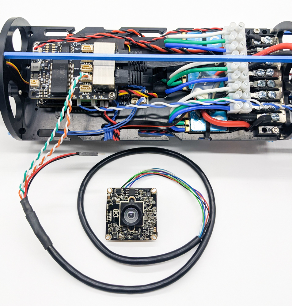
IP camera cable spliced with a JST-GH twisted pair cable and connected to the Ethernet Switch.
Troubleshooting
Cannot connect to ROV
- Check the power indicator light on the Ethernet Switch. If it is off, check if the power connector is fully seated and the spade connectors are connected correctly to the proper power terminals.
- Check the activity indicator lights for ports 1 and 5. If they are not illuminated, check that the Ethernet cables are properly connected and the devices are powered on.
- If the Fathom-x Tether Interface Board and the Raspberry Pi are connected to the RJ45 jacks on ports 1 and 5, make sure no other devices are connected to the JST-GH connectors on the same ports.
- If the previous steps did not resolve the problem please refer to the troubleshooting steps at ArduSub.com.
Cannot connect to a device
- Check the activity indicator light for the port the device is connected to. If it is not illuminated, check the cable connections and make sure the device is powered on.
- Make sure multiple devices are not connected to both the JST-GH connector and the RJ45 jack on ports 1 and 5.
- Check your device’s IP or network configuration.
Feedback
We’re always trying to make our documentation, instructions, and user experience better. If you’d like to leave feedback about how we can make this guide better, let us know here.