
Camera Tilt System Assembly Guide
Introduction
The Camera Tilt System allows any of our three cameras, the HD Low-Light USB Camera, Raspberry Pi Camera, and Analog Low-light Camera, to tilt up and down inside a watertight enclosure. It fits on the front of the 4″ Series electronics tray but can be used in other settings as well.3D Printer Settings
The Camera Tilt System parts are 3D printable. Here are the printer settings that we used with a Lulzbot Taz 5 3D printer and Simplify3D slicing software.
CAMTILT-PRINTER-SETTINGS-R1.fff
Parts and Tools
You Will Need
You will also need:
- #000 Phillips Screwdriver (or similar small size)
- 1.5 mm Hex Driver
- Wire Cutters
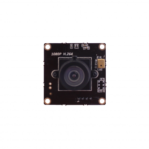
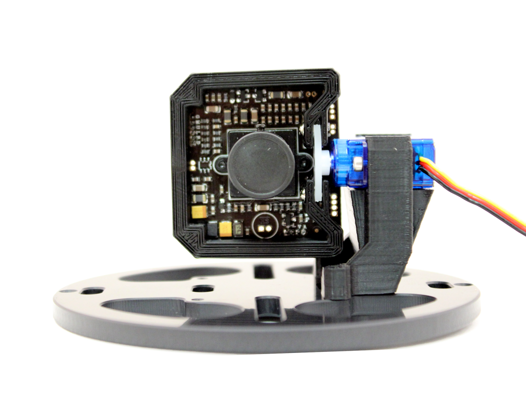
Low-Light HD USB Camera
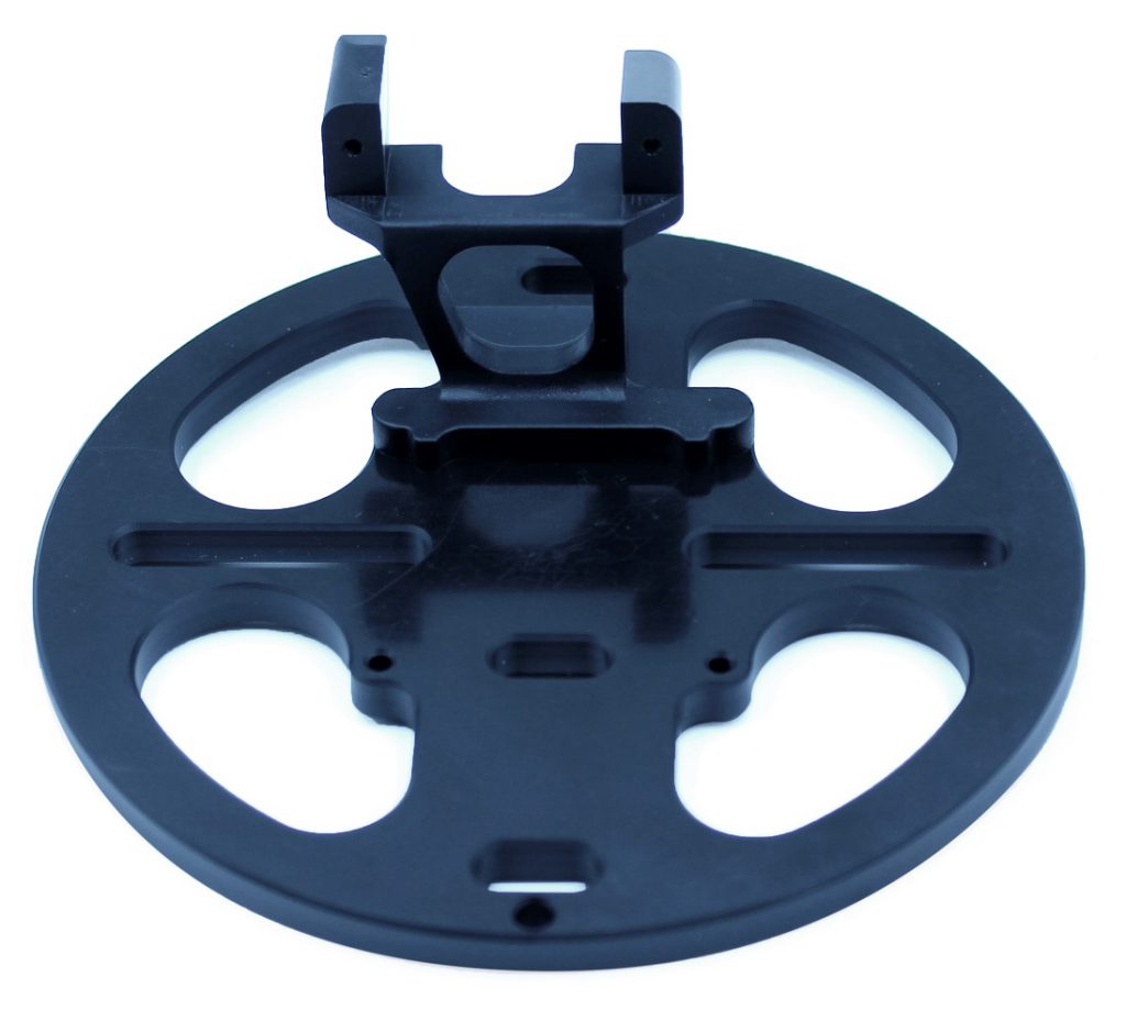
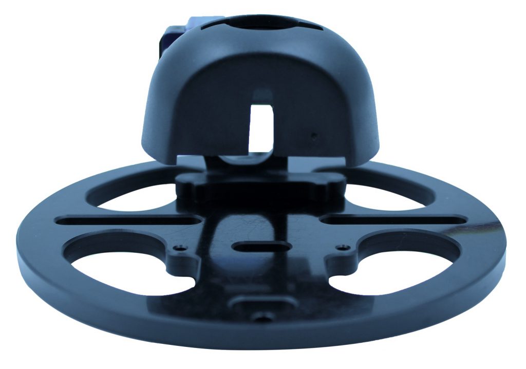
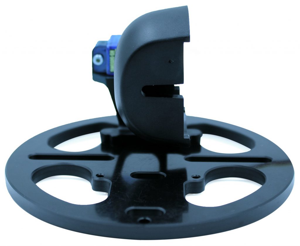
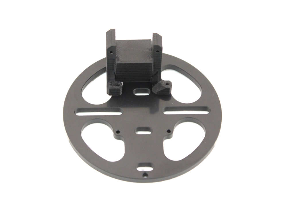
Attach the servo mount to the front tray of the Electronics Tray using 2 of the M2x8 screws.
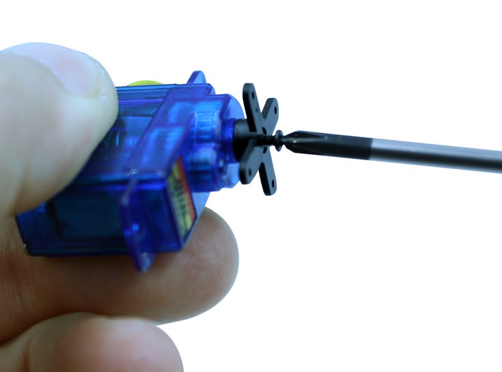
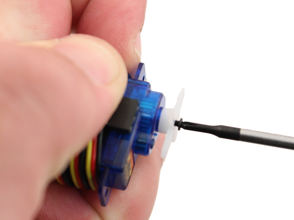
Open the servo box and remove the servo arm that comes installed on the servo using a #000 Philips screwdriver. Place the screw that held on that servo arm in a safe place.
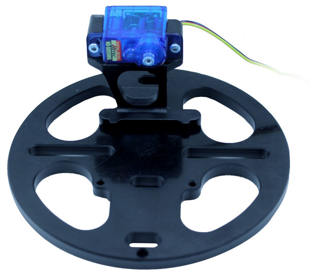
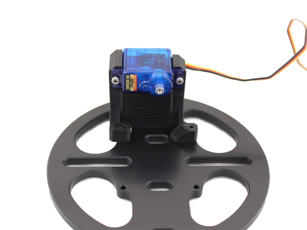
Install the servo on the servo mount using 2 of the M2x8 screws.
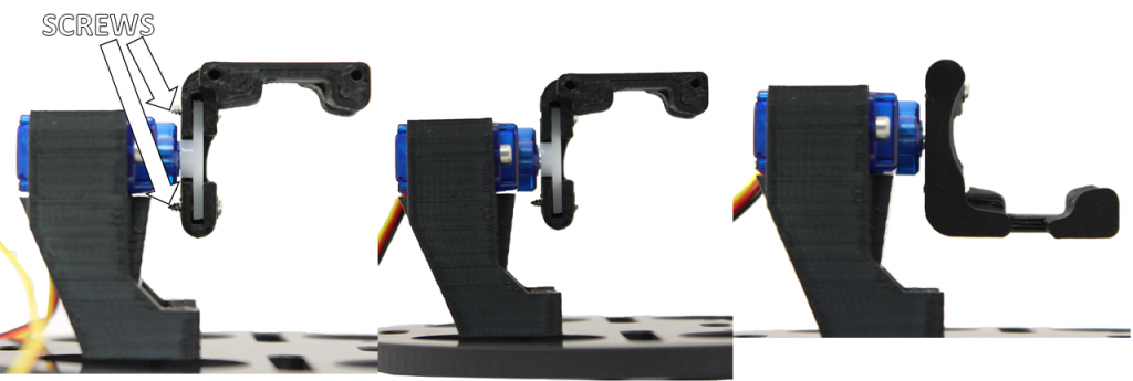
Install the camera mount onto the servo.
a. Place the camera mount on the servo horizontally and then rotate it as far counter-clockwise as possible.
b. If the camera mount is now approximately vertical, reinstall the servo arm screw. If it is not vertical, remove it and place it as near vertical as possible then reinstall the servo arm screw.
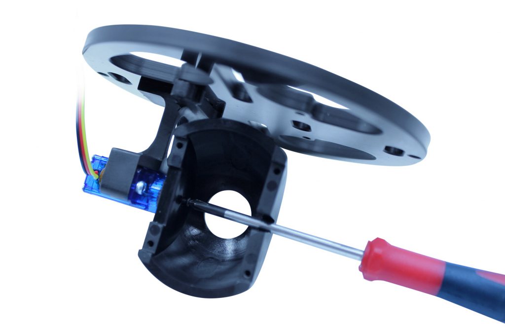
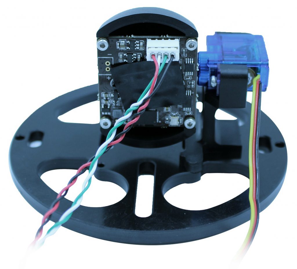
Attach the camera to the camera mount using four M2x8 screws.
Raspberry Pi Camera
Attach the servo mount to the front tray of the Electronics Tray using 2 of the M2x8 screws.
Open the servo box and remove the servo arm that comes installed on the servo using a #000 Philips screwdriver. Place the screw that held on that servo arm in a safe place.
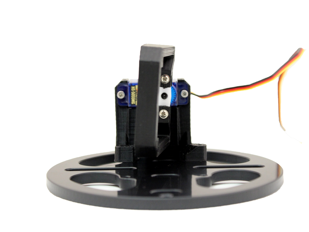
Install the servo on the servo mount using 2 of the M2x8 screws.
Install the servo arm onto the servo.
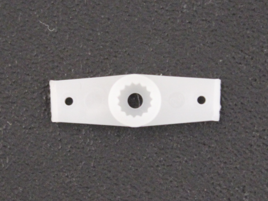
a. Grab the servo arm shown below from the bag that came in the servo box.
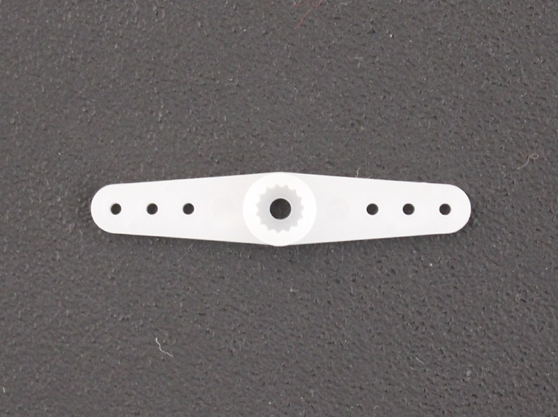
b. Trim off the ends of the servo arm so that only one screw hole remains on both sides.
c. Place the servo arm back on the servo horizontally and then rotate it as far clockwise as possible.
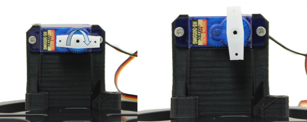
d. If the servo arm is now approximately vertical, reinstall the servo arm screw. If it is not vertical, remove it and place it as near vertical as possible then reinstall the servo arm screw.
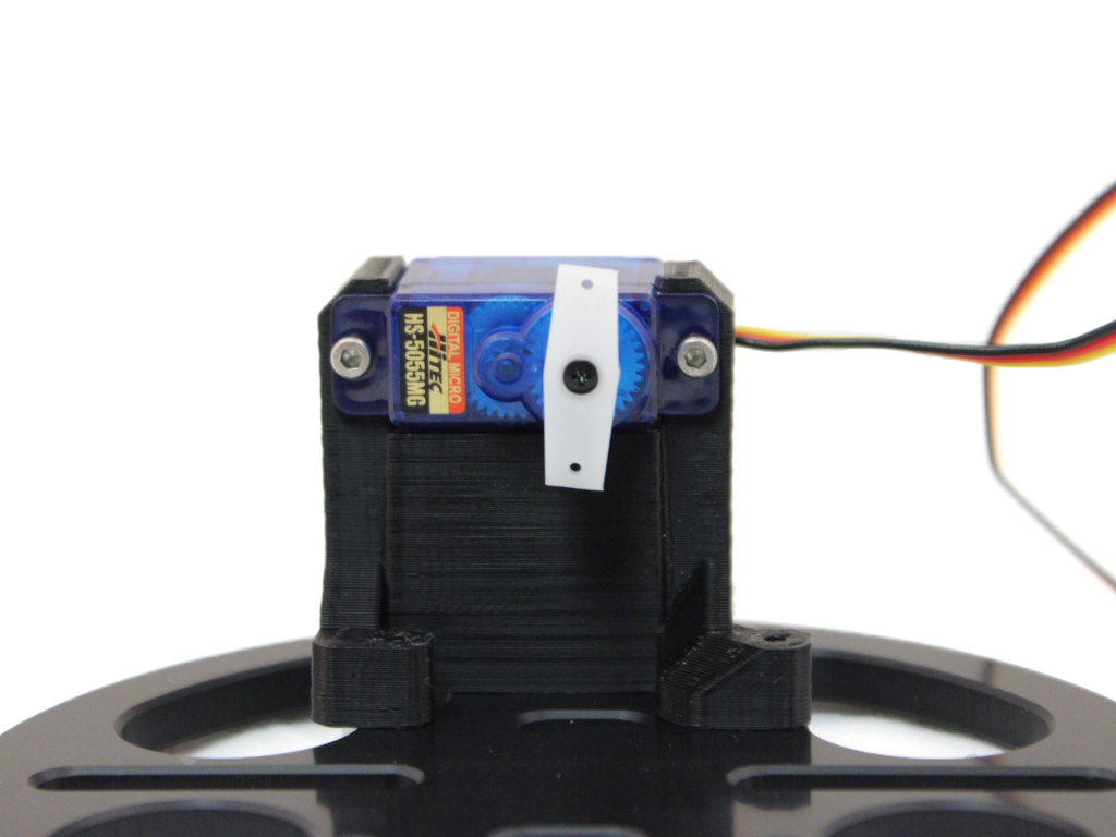
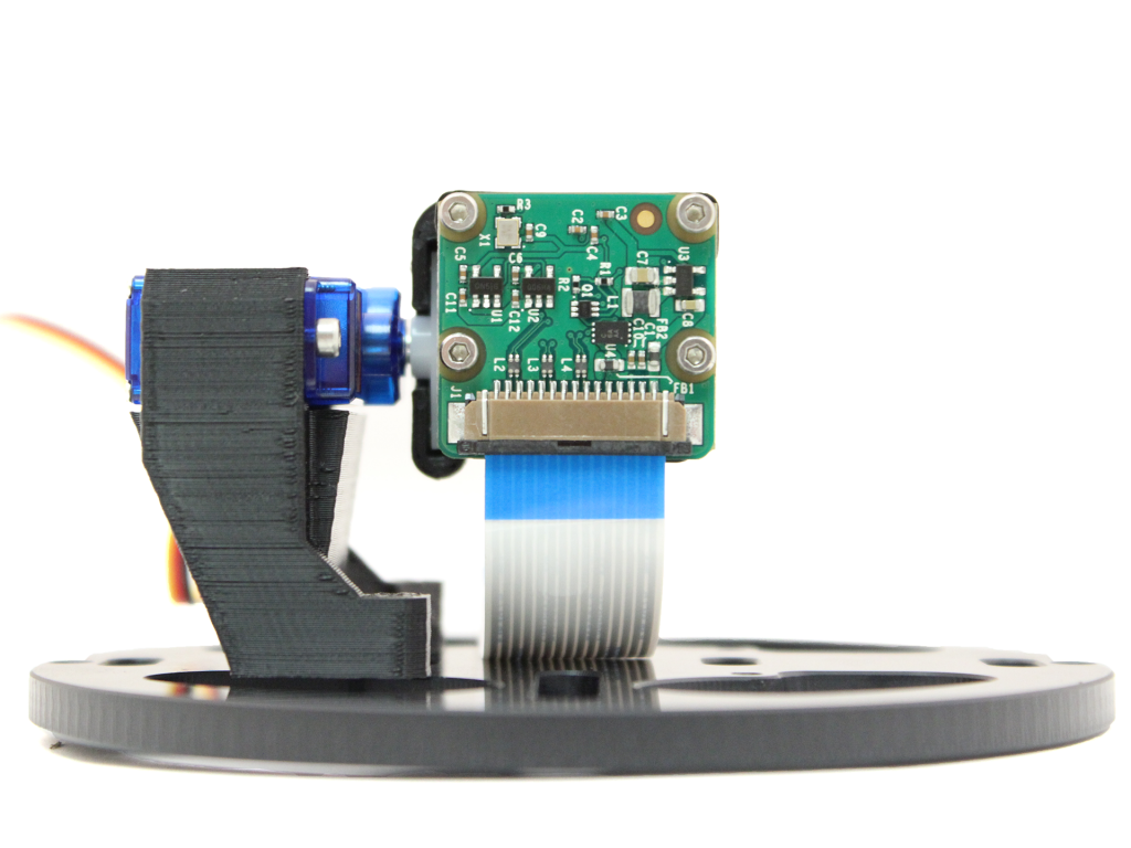
Install the camera mount onto the servo arm using the self-tapping screws that came in the servo box. Keep the servo arm in the vertical position from the last step and have the orientation match the picture below.
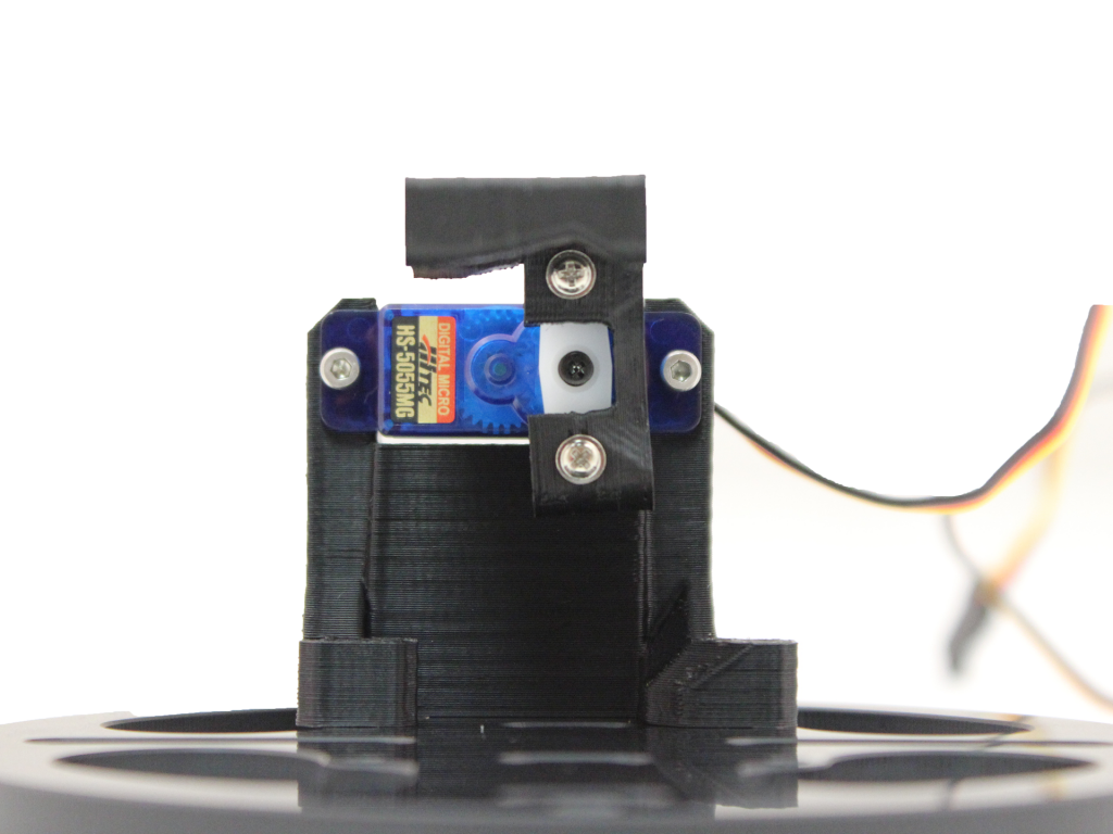
Trim the threads that stick out of the back of the camera mount. Be sure to wear safety glasses. Trim the top screw first then rotate the mount so the bottom screw is on top, then trim the second screw.
Attach the camera to the camera mount using M2x8 screws.
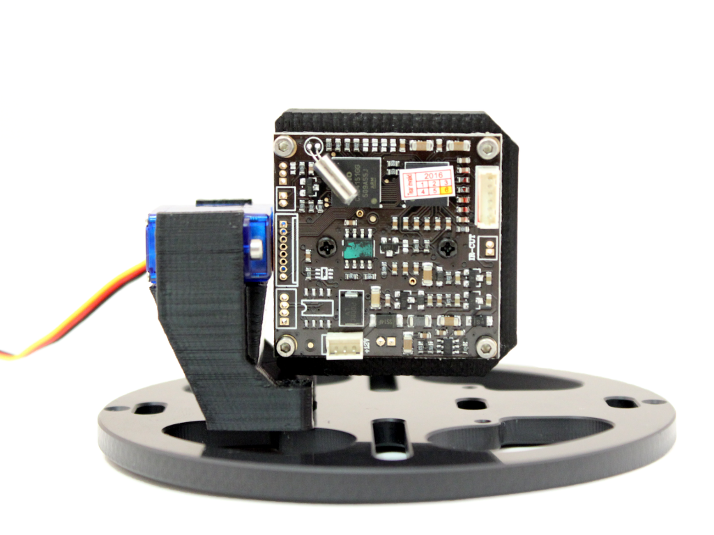
Low-Light Analog Camera
Attach the servo mount to the front tray of the Electronics Tray using 2 of the M2x8 screws.
Open the servo box and remove the servo arm that comes installed on the servo using a #000 Philips screwdriver. Place the screw that held on that servo arm in a safe place.
Install the servo on the servo mount using 2 of the M2x8 screws.
Install the servo arm onto the servo.
a. Grab the servo arm shown below from the bag that came in the servo box.
b. Trim off the ends of the servo arm so that only one screw hole remains on both sides.
c. Place the servo arm back on the servo horizontally and then rotate it as far clockwise as possible.
d. If the servo arm is now approximately vertical, reinstall the servo arm screw. If it is not vertical, remove it and place it as near vertical as possible then reinstall the servo arm screw.
Install the camera mount onto the servo arm using the self-tapping screws that came in the servo box. Keep the servo arm in the vertical position from the last step and have the orientation match the picture below.
Trim the threads that stick out of the back of the camera mount. Be sure to wear safety glasses. Trim the top screw first then rotate the mount so the bottom screw is on top, then trim the second screw.
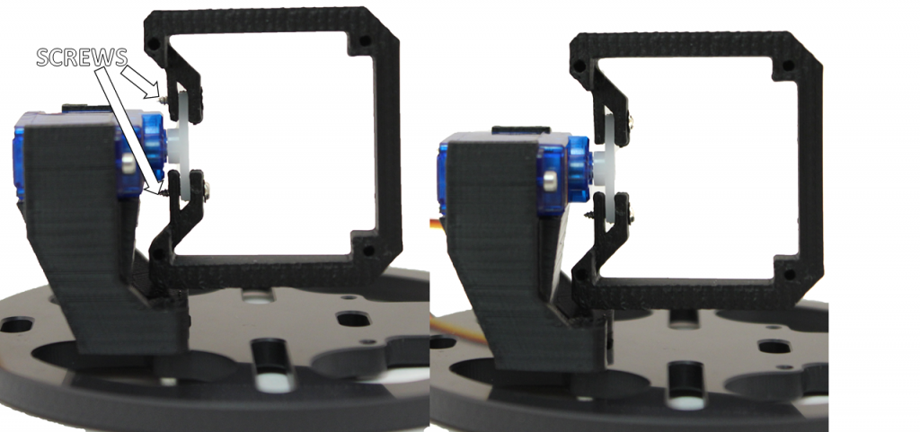
Attach the camera to the camera mount using M2x8 screws. The screw on the lens holder should be on the top side.
Example Code
Arduino
This example uses the Arduino Servo library to control the servo. This provides an update rate of 50 Hz and can use any pin on the Arduino board as the “servoPin”.
If you’ve never used Arduino before, we suggest checking out some tutorials!
#includebyte servoPin = 9; Servo servo; void setup() { servo.attach(servoPin); servo.writeMicroseconds(1500); // send "neutral" signal to the servo } void loop() { int signal = 1700; // Set signal value, which should be between 1100 and 1900 servo.writeMicroseconds(signal); // Send signal to the servo }