
Advanced ROV Electronics Package Assembly Guide
By Daniel
Introduction
The Advanced ROV Electronics Package provides all of the electronics needed for an ArduSub-powered ROV. This guide will show you how everything should be connected and assembled.

Check out the ArduSub documentation for more information about how all of the hardware and software components work together.
Parts and Tools
You Will Need
You will also need the following (not included in the kit):
- Cable with at least two wires for ROV communication to the surface computer. This could be tether, network cable, or just two regular wires.
- 1x Ethernet cable
- 1x Mini USB to USB A cable
- A small (#1) Phillips head screwdriver
- A small (2 mm) flat head screwdriver
Additional Items
These items aren’t necessary but may be useful:
- Multi position terminal block (for power distribution)
- Ethernet to USB adapter
SD Cards
1. The kit includes a micro SD card preloaded with the Companion Software for the Raspberry Pi. Remove the micro SD card from the adapter and install it in the micro SD card slot on the Raspberry Pi.
2. The Pixhawk uses a micro SD card to record data logs. It should be preinstalled in the micro SD card slot, check to verify it is there.
Mounting the Electronics
For this step you will need:
- 1x Raspberry Pi 3B
- 1x Pixhawk autopilot
- 1x Fathom-X interface Board
- 1x Pixhawk shelf
- 8x Phillips head thread forming screws
- 6x small white spacers
- Small Phillips screwdriver
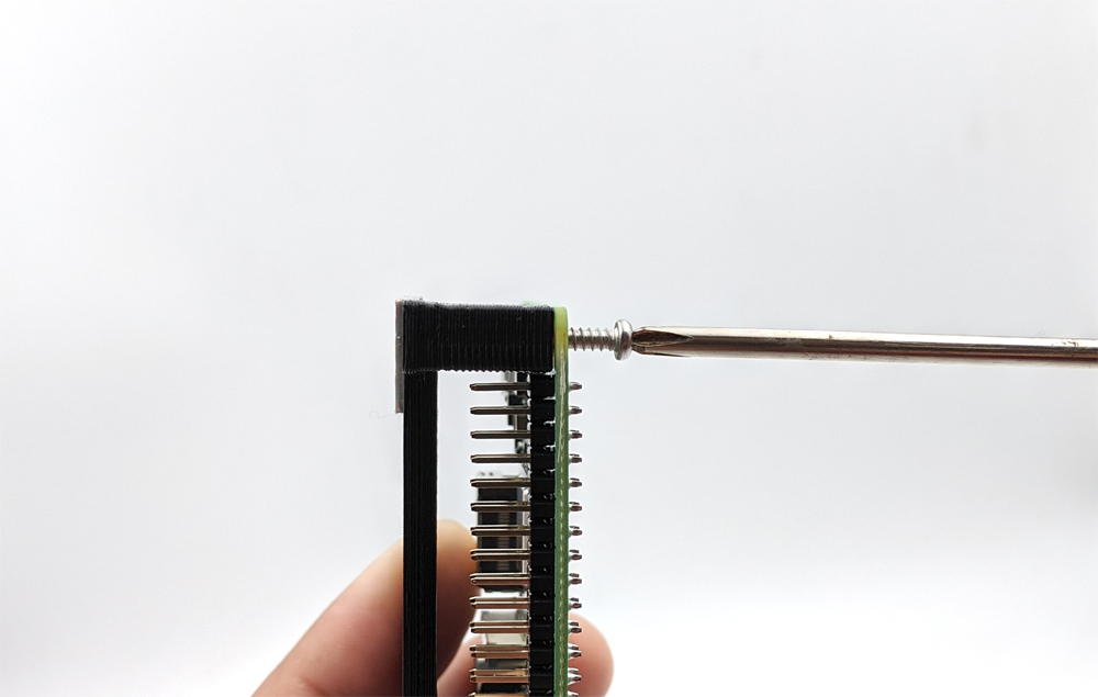
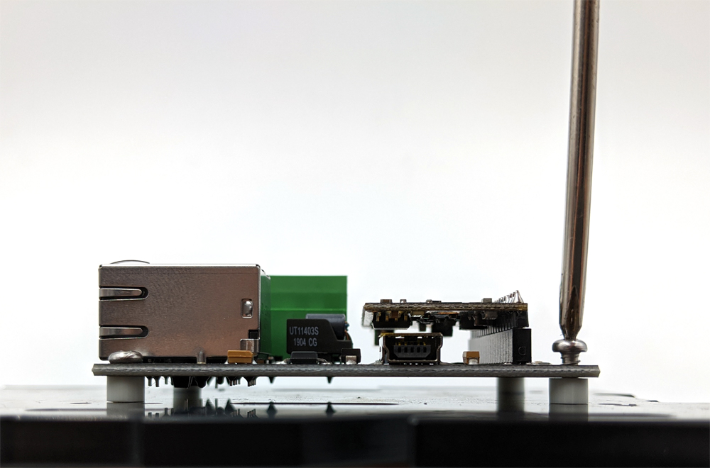
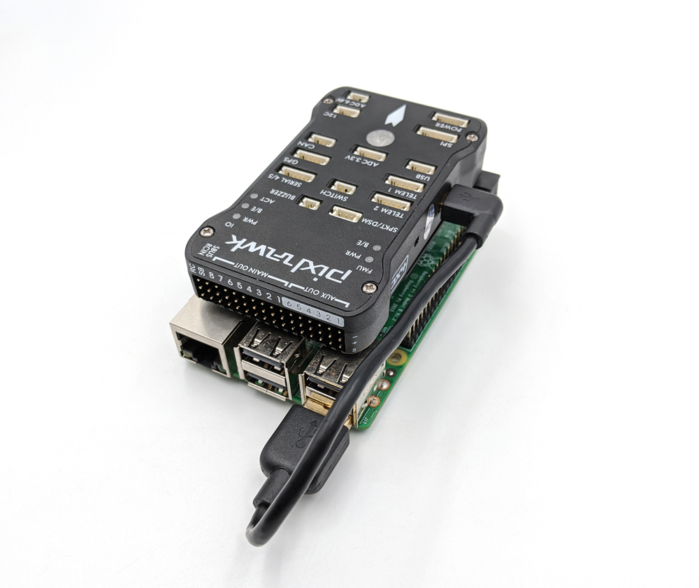
1. Place the Pixhawk shelf on top of the Raspberry Pi and secure it with two Phillips head thread forming screws.
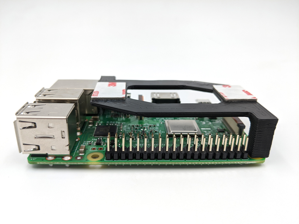
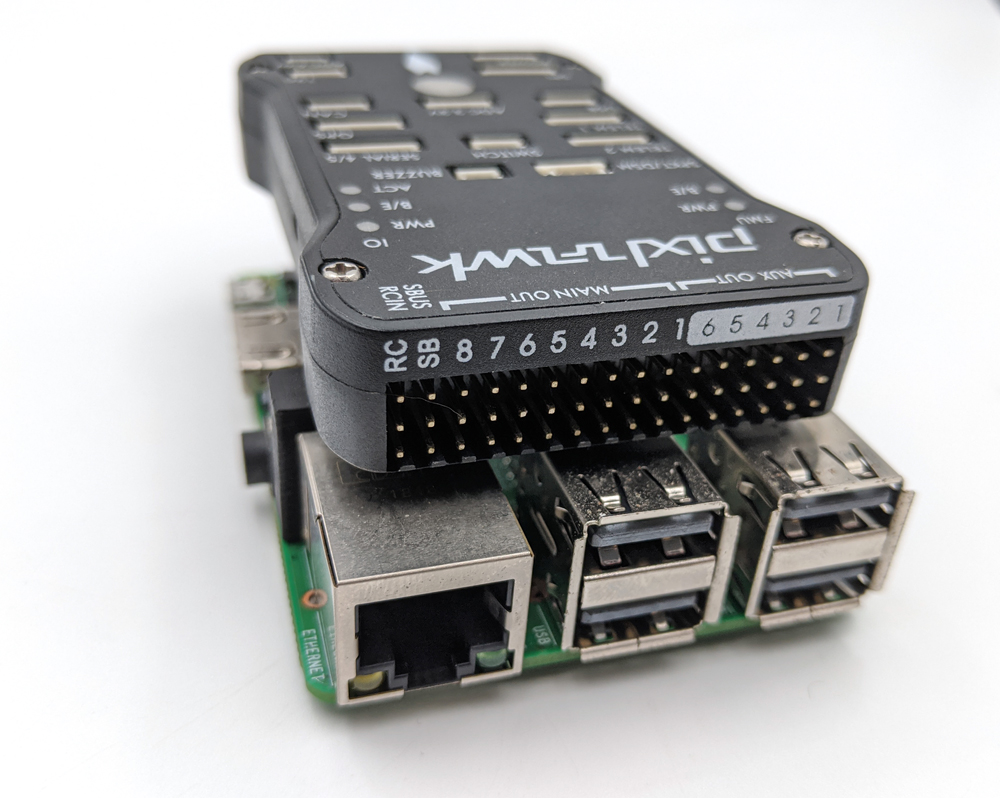
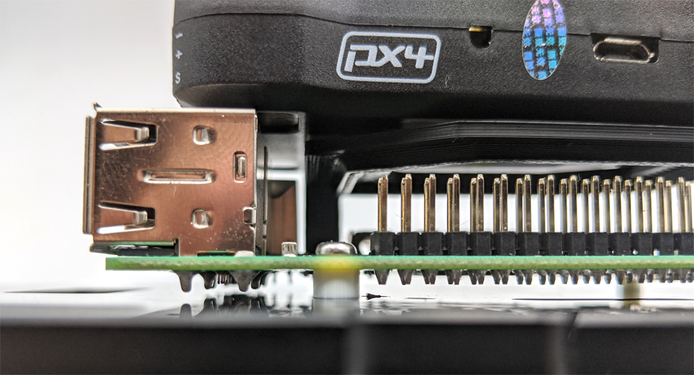
2. Remove the cover from the pieces of mounting tape on the Pixhawk shelf and stick the Pixhawk on top. The Pixhawk servo rail should be on the same side as the Raspberry Pi USB ports.
3. Use two more Phillips head thread forming screws and two small, white spacers to mount the Raspberry Pi/Pixhawk assembly to the vehicle or electronics tray.
4. The remaining four Phillips head thread forming screws and four spacers can be used to mount the Fathom-X board to the vehicle or electronics tray.
Wire and Cable Connections
1. Use the left angle Micro USB cable to connect the Pixhawk and Raspberry Pi.
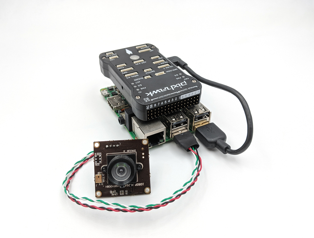
2. Connect the Low Light USB camera to the Raspberry Pi using the supplied USB cable.
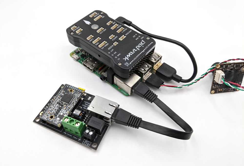
3. Use the 6” Ethernet cable included with the Fathom-X board set to connect the Fathom-X board mounted in the vehicle to the Raspberry Pi.
Power Connections
Power Sense Module
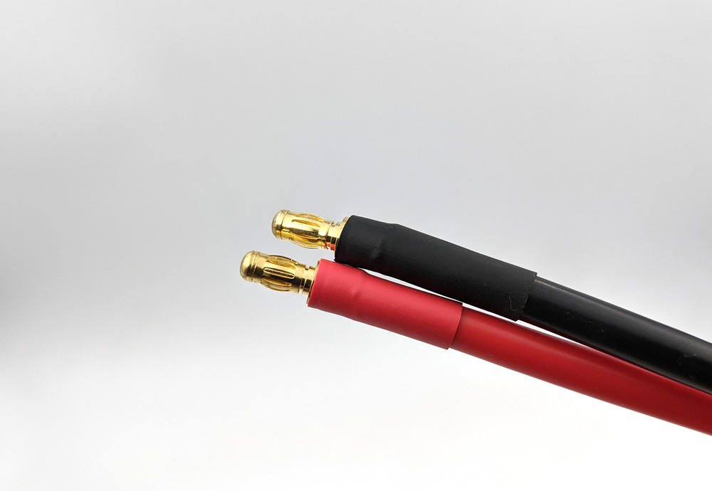
The Power Sense Module is connected between the battery or power supply and the power distribution block to provide voltage and current sensing information.
1. The end of the Power Sense Module that terminates in 3.5mm male bullet connectors should connect to the battery or power source via an appropriate adapter (not supplied).
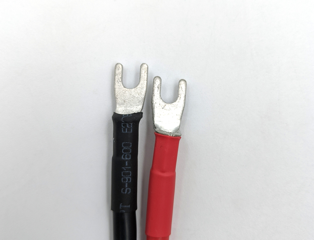
2. The spade connectors on the other end will connect to the power distribution block in the vehicle.
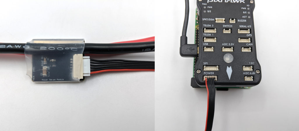
3. The cable included with the Power Sense Module has different connectors on each end (6-position JST-GH to DF13). Plug the JST-GH connector into the JST-GH socket on the Power Sense Module and the DF13 connector into the DF13 “POWER” socket on the Pixhawk.
5V 6A Power Supply
The 5V 6A Power Supply is used to supply power to the Raspberry Pi and the Pixhawk servo rail.
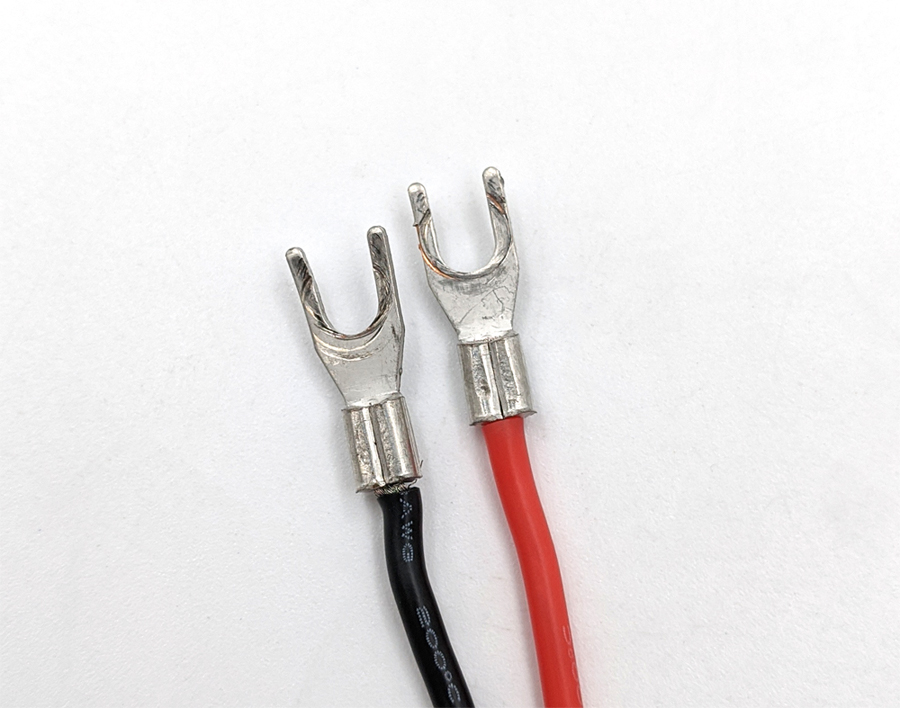
1. Connect the spade connectors from the 5V 6A power supply to the power distribution block.
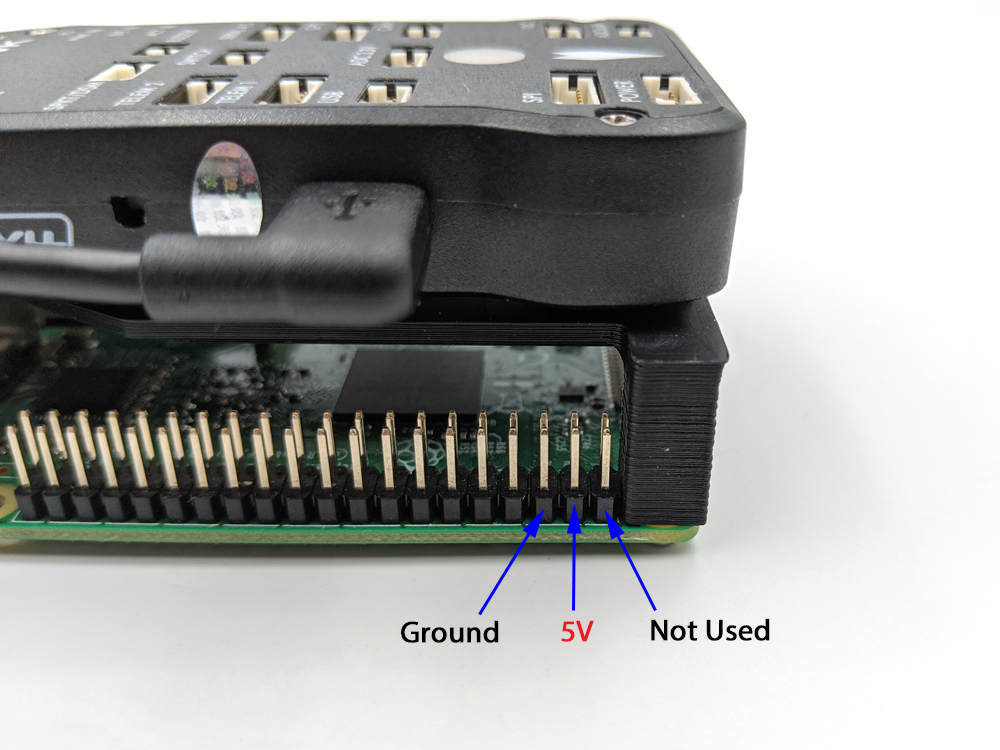
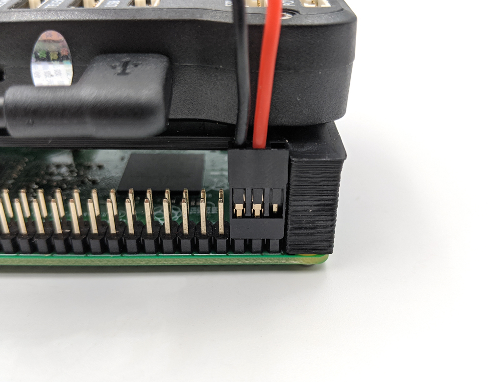
2. The other side of the 5V 6A power supply has two 3-position servo connectors. Plug one of these connectors onto GPIO pins 2, 4, and 6 on the Raspberry Pi (see here for GPIO pin numbering). The 5V (red) wire should connect to GPIO pin 4 and the ground (black) wire should connect to GPIO pin 6. The remaining position on the connector is not used.
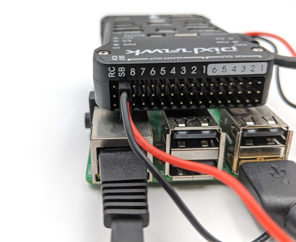
3. Connect the other servo connector onto the “SBUS” (“SB”) channel on the Pixhawk with the ground wire in the top position.
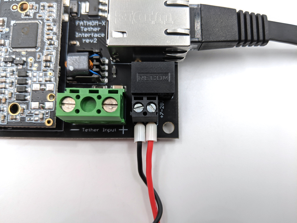
Fathom-X Power
1. Take the ferrule to spade cable and connect the spade connectors to the power distribution.
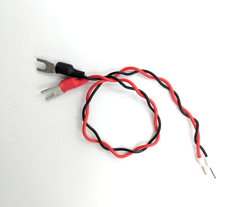
Insert the ferrule from the red wire into “BATT+” and the ferrule from the black wire into “BATT-” on the Fathom-X. Tighten the connectors using a small flat head screwdriver.
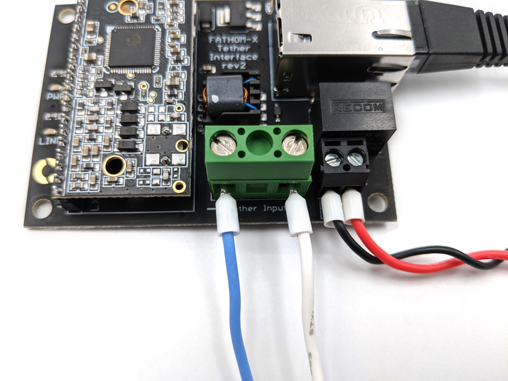
Tether
The Fathom-X Tether Interface Boards require two wires for vehicle telemetry and video streaming.
1. Connect one wire to “Tether Input +” and the other to “Tether Input -“. Tighten the connectors with a a small flat head screwdriver.
That should complete all of the connections for the Advanced ROV Electronics components installed in the vehicle. The next section will go over topside setup.
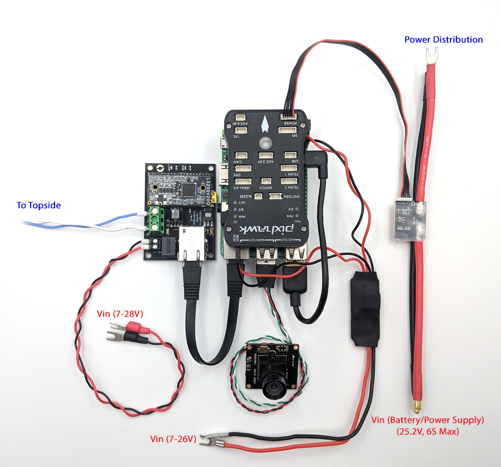
All of the vehicle components.
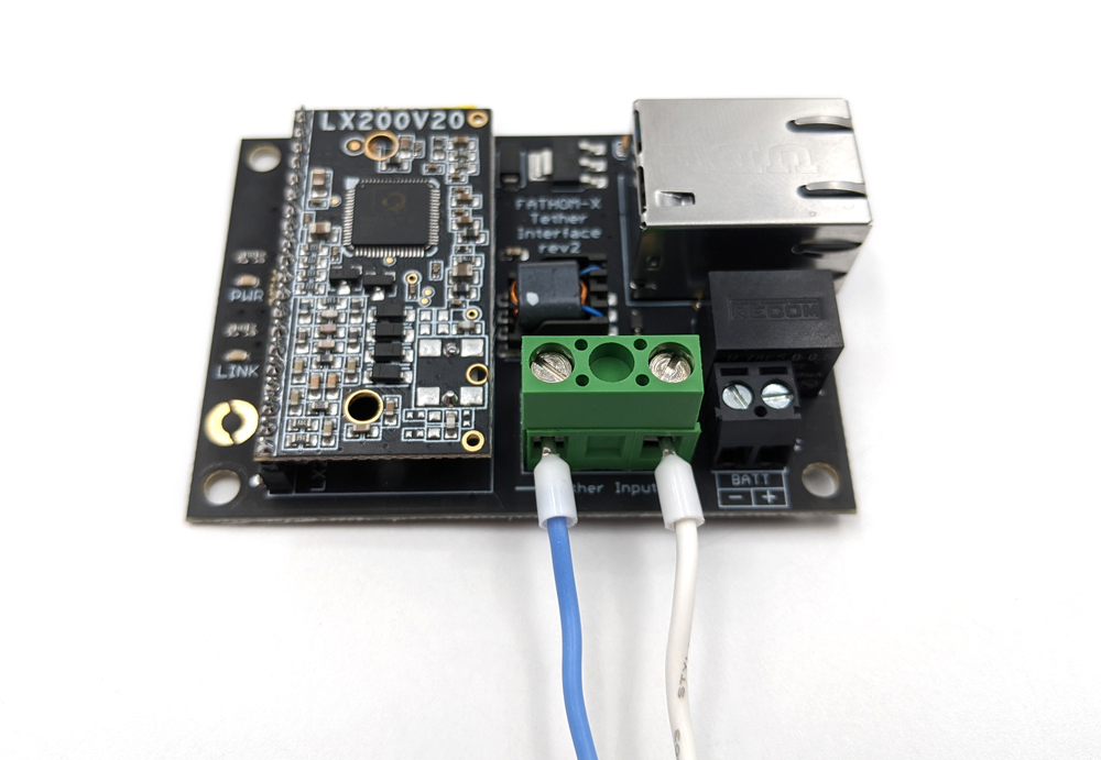
Topside Connections
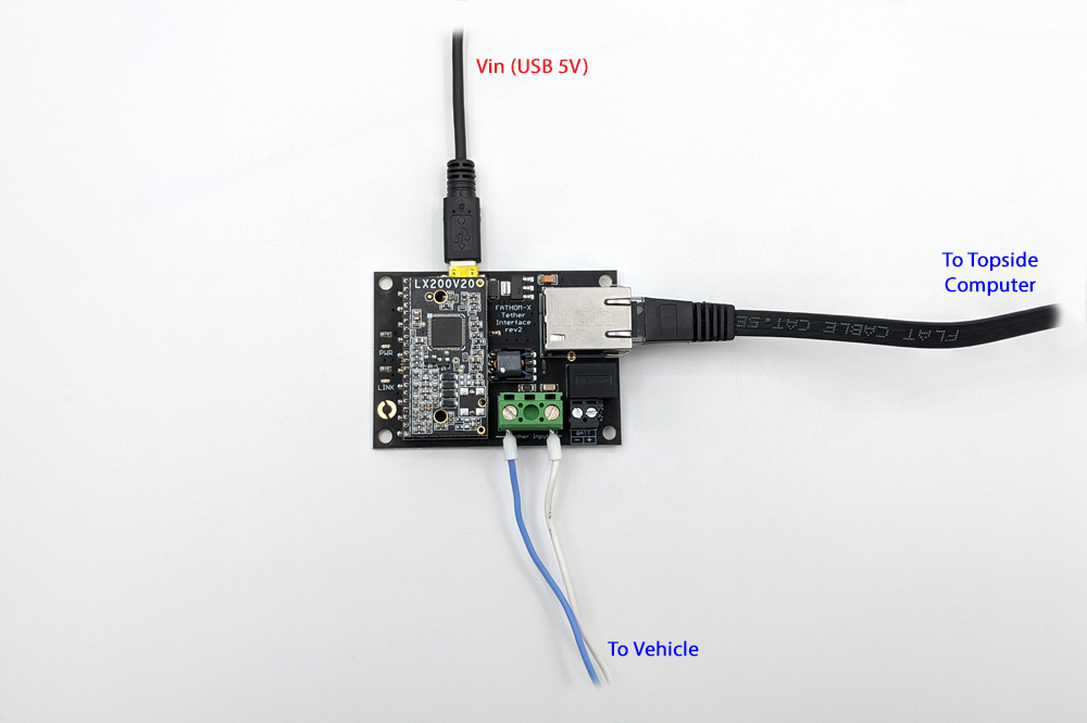
The other Fathom-X Tether Interface Board will be used on the other end of the tether and connect to the topside computer.
1. Connect the other ends of the two tether wires to the topside Fathom-X tether input. The tether input wires should connect “+” to “+” and “-” to “-”.
2. A mini USB cable (not included) can be used to supply 5V power to the topside Fathom-X board. Connect a mini USB cable to the Fathom-X and the other end to a computer or 5V supply.
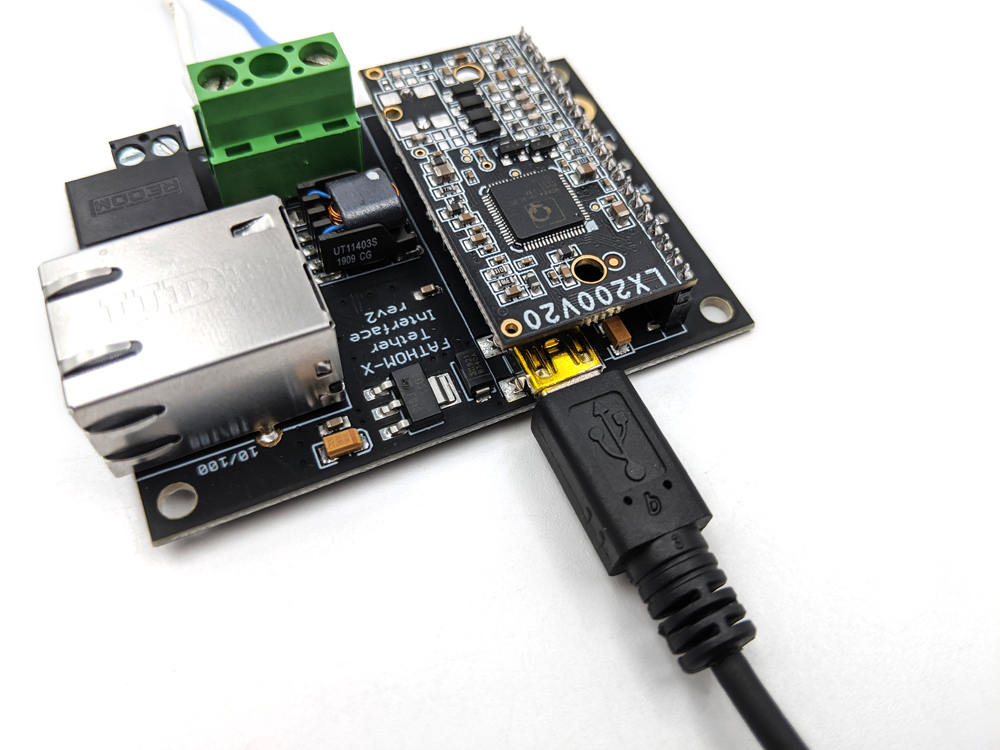
3. Use an Ethernet cable (not included) to connect the Fathom-X to the topside computer’s Ethernet port. For laptops or computers without an available Ethernet port, an Ethernet to USB adapter can be used.
Next Steps
Continue with the instructions in the ArduSub documentation for setting up the software and configuring network settings.
Be sure to visit the forums to share and check out other DIY ROV builds!
What did you think of this guide? Could it be better? Let us know here!
Authors

Daniel
Daniel is the Product Specialist at Blue Robotics and is an expert at working with all elements of our product line!